2011 INFINITI QX56 key
[x] Cancel search: keyPage 4099 of 5598
PWC-14
< ECU DIAGNOSIS INFORMATION >
POWER WINDOW MAIN SWITCH
POWER WINDOW MAIN SWITCH
Reference Value INFOID:0000000006217272
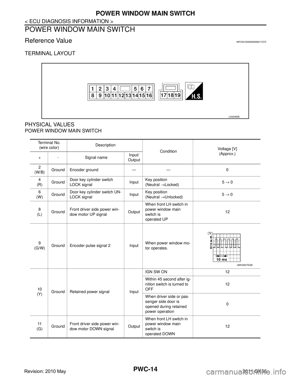
TERMINAL LAYOUT
PHYSICAL VALUES
POWER WINDOW MAIN SWITCH
LIIA2455E
Te r m i n a l N o .(wire color) Description
ConditionVoltage [V]
(Approx.)
+ - Signal name Input/
Output
2
(W/B) Ground Encoder ground — — 0
4
(R) Ground Door key cylinder switch
LOCK signal
InputKey position
(Neutral
→Locked) 5
→ 0
6
(W) Ground
Door key cylinder switch UN-
LOCK signal Input
Key position
(Neutral
→Unlocked) 5
→ 0
8
(L) Ground Front driver side power win-
dow motor UP signal
OutputWhen front LH switch in
power window main
switch is
operated UP 12
9
(G/W) Ground Encoder pulse signal 2 Input When power window mo-
tor operates.
10
(Y) Ground Retained power signal Input IGN SW ON 12
Within 45 second after ig-
nition switch is turned to
OFF
12
When driver side or pas-
senger side door is
opened during retained
power operation 0
11
(G) Ground
Front driver side power win-
dow motor DOWN signal OutputWhen front LH switch in
power window main
switch is
operated DOWN 12
JMKIA0070GB
Revision: 2010 May2011 QX56
Page 4138 of 5598
DOOR KEY CYLINDER SWITCHPWC-53
< DTC/CIRCUIT DIAGNOSIS >
C
DE
F
G H
I
J
L
M A
B
PWC
N
O P
DOOR KEY CYLINDER SWITCH
Component Function CheckINFOID:0000000006217309
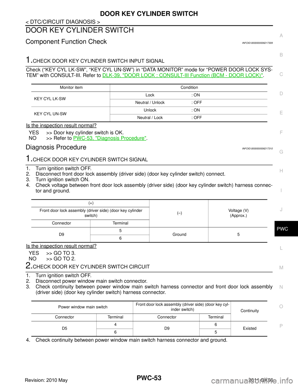
1.CHECK DOOR KEY CYLINDER SWITCH INPUT SIGNAL
Check (“KEY CYL LK-SW”, “KEY CYL UN-SW”) in “D ATA MONITOR” mode for “POWER DOOR LOCK SYS-
TEM” with CONSULT-III. Refer to DLK-39, "
DOOR LOCK : CONSULT-III Function (BCM - DOOR LOCK)".
Is the inspection result normal?
YES >> Door key cylinder switch is OK.
NO >> Refer to PWC-53, "
Diagnosis Procedure".
Diagnosis ProcedureINFOID:0000000006217310
1.CHECK DOOR KEY CYLINDER SWITCH SIGNAL
1. Turn ignition switch OFF.
2. Disconnect front door lock assembly (driver side) (door key cylinder switch) connect.
3. Turn ignition switch ON.
4. Check voltage between front door lock assembly (dri ver side) (door key cylinder switch) harness connec-
tor and ground.
Is the inspection result normal?
YES >> GO TO 3.
NO >> GO TO 2.
2.CHECK DOOR KEY CYLINDER SWITCH CIRCUIT
1. Turn ignition switch OFF.
2. Disconnect power window main switch connector.
3. Check continuity between power window main switch harness connector and front door lock assembly (driver side) (door key cylinder switch) harness connector.
4. Check continuity between power window main switch harness connector and ground.
Monitor item Condition
KEY CYL LK-SW Lock : ON
Neutral / Unlock : OFF
KEY CYL UN-SW Unlock : ON
Neutral / Lock : OFF
(+)
(–)Voltage (V)
(Approx.)
Front door lock assembly (driver side) (door key cylinder
switch)
Connector Terminal
D9 5
Ground 5
6
Power window main switch Front door lock assembly
(driver side) (door key cyl-
inder switch) Continuity
Connector Terminal Connector Terminal
D5 4
D9 6
Existed
65
Revision: 2010 May2011 QX56
Page 4139 of 5598
PWC-54
< DTC/CIRCUIT DIAGNOSIS >
DOOR KEY CYLINDER SWITCH
Is the inspection result normal?
YES >> Replace power window main switch. Refer to PWC-74, "Removal and Installation".
NO >> Repair or replace harness.
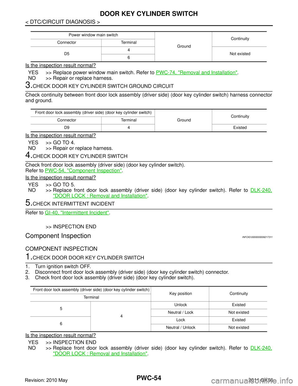
3.CHECK DOOR KEY CYLINDER SWITCH GROUND CIRCUIT
Check continuity between front door lock assembly (d river side) (door key cylinder switch) harness connector
and ground.
Is the inspection result normal?
YES >> GO TO 4.
NO >> Repair or replace harness.
4.CHECK DOOR KEY CYLINDER SWITCH
Check front door lock assembly (driver side) (door key cylinder switch).
Refer to PWC-54, "
Component Inspection".
Is the inspection result normal?
YES >> GO TO 5.
NO >> Replace front door lock assembly (driver side) (door key cylinder switch). Refer to DLK-240,
"DOOR LOCK : Removal and Installation".
5.CHECK INTERMITTENT INCIDENT
Refer to GI-40, "
Intermittent Incident".
>> INSPECTION END
Component InspectionINFOID:0000000006217311
COMPONENT INSPECTION
1.CHECK DOOR DOOR KEY CYLINDER SWITCH
1. Turn ignition switch OFF.
2. Disconnect front door lock assembly (drive r side) (door key cylinder switch) connector.
3. Check front door lock assembly (driver side) (door key cylinder switch).
Is the inspection result normal?
YES >> INSPECTION END
NO >> Replace front door lock assembly (driver side) (door key cylinder switch). Refer to DLK-240,
"DOOR LOCK : Removal and Installation".
Power window main switch
GroundContinuity
Connector Terminal
D5 4
Not existed
6
Front door lock assembly (driver side) (door key cylinder switch)
GroundContinuity
Connector Terminal
D9 4 Existed
Front door lock assembly (driver side) (door key cylinder switch)
Key position Continuity
Te r m i n a l
5 4Unlock Existed
Neutral / Lock Not existed
6 Lock Existed
Neutral / Unlock Not existed
Revision: 2010 May2011 QX56
Page 4155 of 5598
PWC-70
< SYMPTOM DIAGNOSIS >
DOOR KEY CYLINDER SWITCH DOES NOT OPERATE POWER WINDOWS
DOOR KEY CYLINDER SWITCH DOES NOT OPERATE POWER WIN-
DOWS
Diagnosis ProcedureINFOID:0000000006217337
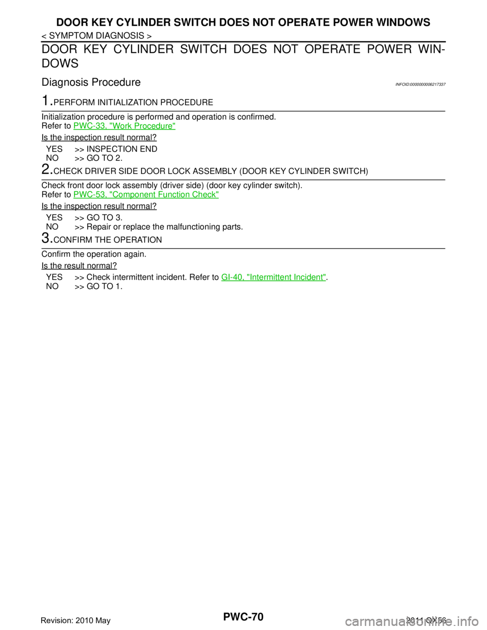
1.PERFORM INITIALIZATION PROCEDURE
Initialization procedure is performed and operation is confirmed.
Refer to PWC-33, "
Work Procedure"
Is the inspection result normal?
YES >> INSPECTION END
NO >> GO TO 2.
2.CHECK DRIVER SIDE DOOR LOCK AS SEMBLY (DOOR KEY CYLINDER SWITCH)
Check front door lock assembly (driver side) (door key cylinder switch).
Refer to PWC-53, "
Component Function Check"
Is the inspection result normal?
YES >> GO TO 3.
NO >> Repair or replace the malfunctioning parts.
3.CONFIRM THE OPERATION
Confirm the operation again.
Is the result normal?
YES >> Check intermittent incident. Refer to GI-40, "Intermittent Incident".
NO >> GO TO 1.
Revision: 2010 May2011 QX56
Page 4156 of 5598
KEYLESS POWER WINDOW DOWN DOES NOT OPERATE
PWC-71
< SYMPTOM DIAGNOSIS >
C
D E
F
G H
I
J
L
M A
B
PWC
N
O P
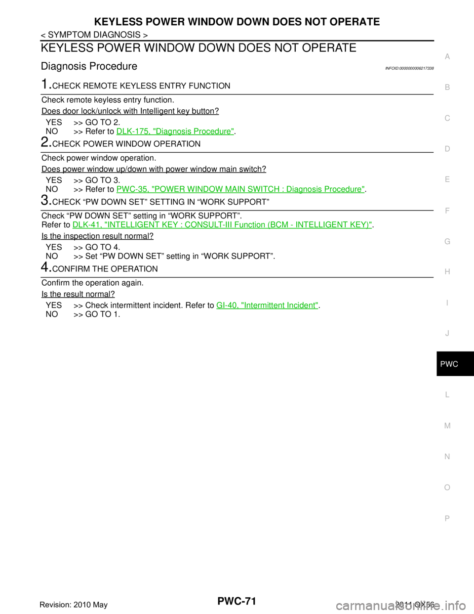
KEYLESS POWER WINDOW DOWN DOES NOT OPERATE
Diagnosis ProcedureINFOID:0000000006217338
1.CHECK REMOTE KEYLESS ENTRY FUNCTION
Check remote keyless entry function.
Does door lock/unlock with Intelligent key button?
YES >> GO TO 2.
NO >> Refer to DLK-175, "
Diagnosis Procedure".
2.CHECK POWER WINDOW OPERATION
Check power window operation.
Does power window up/down with power window main switch?
YES >> GO TO 3.
NO >> Refer to PWC-35, "
POWER WINDOW MAIN SWITCH : Diagnosis Procedure".
3.CHECK “PW DOWN SET” SETTING IN “WORK SUPPORT”
Check “PW DOWN SET” setting in “WORK SUPPORT”.
Refer to DLK-41, "
INTELLIGENT KEY : CONSULT-III F unction (BCM - INTELLIGENT KEY)".
Is the inspection result normal?
YES >> GO TO 4.
NO >> Set “PW DOWN SET” setting in “WORK SUPPORT”.
4.CONFIRM THE OPERATION
Confirm the operation again.
Is the result normal?
YES >> Check intermittent incident. Refer to GI-40, "Intermittent Incident".
NO >> GO TO 1.
Revision: 2010 May2011 QX56
Page 4473 of 5598
SE-14
< SYSTEM DESCRIPTION >
COMPONENT PARTS
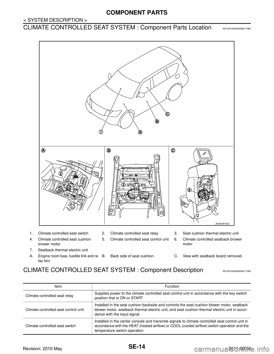
CLIMATE CONTROLLED SEAT SYSTEM : Component Parts Location
INFOID:0000000006217368
CLIMATE CONTROLLED SEAT SYSTEM : Component DescriptionINFOID:0000000006217369
1. Climate controlled seat switch 2. Climate controlled seat relay 3. Seat cushion thermal electric unit
4. Climate controlled seat cushion
brower motor 5. Climate controlled seat control unit 6. Climate controlled seatback brower
motor
7. Seatback thermal electric unit
A. Engine room fuse, fusible link and re- lay box B. Back side of seat cushion. C. View with seatback board removed.
JMJIA3816ZZ
Item Function
Climate controlled seat relay Supplies power to the climate controlled seat control unit in accordance with the key switch
position that is ON or START
Climate controlled seat control unit Installed in the seat cushion backside and controls the seat cushion blower motor, seatback
blower motor, seatback thermal electric unit, and seat cushion thermal electric unit in accor-
dance with the input signal.
Climate controlled seat switch Installed in the center console and transmits signals to climate controlled seat control unit in
accordance with the HEAT (heated airflow) or COOL (cooled airflow) switch operation and the
temperature switch operation
Revision: 2010 May2011 QX56
Page 4608 of 5598
SEC-1
BODY EXTERIOR, DOORS, ROOF & VEHICLE SECURITY
C
D
E
F
G H
I
J
L
M
SECTION SEC
A
B
SEC
N
O P
CONTENTS
SECURITY CONTROL SYSTEM
WITH INTELLIGE NT KEY SYSTEM
PRECAUTION ................ ...............................
5
PRECAUTIONS .............................................. .....5
Precaution for Supplemental Restraint System
(SRS) "AIR BAG" and "SEAT BELT PRE-TEN-
SIONER" ............................................................. ......
5
Precaution Necessary for Steering Wheel Rota-
tion after Battery Disconnect .....................................
5
Precaution for Procedure without Cowl Top Cover ......6
SYSTEM DESCRIPTION ..............................7
COMPONENT PARTS ................................... .....7
Component Parts Location .................................. ......7
Component Description .............................................8
A/T Shift Selector (Detention Switch) ........................8
BCM ..........................................................................8
ECM ..........................................................................9
IPDM E/R ..................................................................9
NATS Antenna Amp. .................................................9
TCM ..........................................................................9
Combination Meter ....................................................9
Door Switch ...............................................................9
Hood Switch ..............................................................9
Inside Key Antenna ...................................................9
Intelligent Key ............................................................9
Push-button Ignition Switch .....................................10
Remote Keyless Entry Receiver .............................10
Security Indicator Lamp ..........................................10
Starter Control Relay ...............................................10
Starter Relay ...........................................................10
Steering Lock Relay ................................................10
Steering Lock Unit ...................................................10
Stop Lamp Switch ...................................................10
Transmission Range Switch ....................................10
Vehicle Information Display .....................................11
SYSTEM .............................................................12
INTELLIGENT KEY SYSTEM/ENGINE START
FUNCTION ............................................................. ....
12
INTELLIGENT KEY SYSTEM/ENGINE START
FUNCTION : System Diagram ................................
12
INTELLIGENT KEY SYSTEM/ENGINE START
FUNCTION : System Description ............................
12
INFINITI VEHICLE IMMOBILIZER SYSTEM-NATS ....14
INFINITI VEHICLE IMMOBILIZER SYSTEM-
NATS : System Diagram .........................................
15
INFINITI VEHICLE IMMOBILIZER SYSTEM-
NATS : System Description .....................................
15
VEHICLE SECURITY SYSTEM .................................17
VEHICLE SECURITY SYSTEM : System Dia-
gram .................................................................... ....
17
VEHICLE SECURITY SYSTEM : System Descrip-
tion ...........................................................................
18
DIAGNOSIS SYSTEM (BCM) ...........................21
COMMON ITEM ..................................................... ....21
COMMON ITEM : CONSULT-III Function (BCM -
COMMON ITEM) .....................................................
21
INTELLIGENT KEY ................................................ ....22
INTELLIGENT KEY : CONSULT-III Function
(BCM - INTELLIGENT KEY) ....................................
22
THEFT ALM ........................................................... ....26
THEFT ALM : CONSULT-III Function (BCM -
THEFT) ................................................................ ....
26
IMMU ...................................................................... ....27
IMMU : CONSULT-III Function (BCM - IMMU) ........27
DIAGNOSIS SYSTEM (IPDM E/R) ...................28
CONSULT-III Function (IPDM E/R) .........................28
ECU DIAGNOSIS INFORMATION ..............30
ECM, IPDM E/R, BCM .......................................30
List of ECU Reference ......................................... ....30
Revision: 2010 May2011 QX56
Page 4609 of 5598

SEC-2
WIRING DIAGRAM .....................................31
SECURITY CONTROL SYSTEM .................... ...31
Wiring Diagram .................................................... ...31
BASIC INSPECTION ...................................48
DIAGNOSIS AND REPAIR WORK FLOW ..... ...48
Work Flow ............................................................ ...48
ADDITIONAL SERVICE WHEN REPLACING
CONTROL UNIT ................................................
51
ECM ........................................................................ ...51
ECM : Description ...................................................51
ECM : Work Procedure ...........................................51
BCM ........................................................................ ...51
BCM : Description ...................................................51
BCM : Work Procedure ...........................................51
DTC/CIRCUIT DIAGNOSIS ...................... ...53
P1610 LOCK MODE ....................................... ...53
Description ........................................................... ...53
DTC Logic ...............................................................53
Diagnosis Procedure ..............................................53
P1611 ID DISCORD, IMMU-ECM ......................54
DTC Logic ............................................................ ...54
Diagnosis Procedure ..............................................54
P1612 CHAIN OF ECM-IMMU ...........................55
DTC Logic ............................................................ ...55
Diagnosis Procedure ..............................................55
P1614 CHAIN OF IMMU-KEY ...........................56
DTC Logic ............................................................ ...56
Diagnosis Procedure ..............................................56
B2192 ID DISCORD, IMMU-ECM ......................60
DTC Logic ............................................................ ...60
Diagnosis Procedure ..............................................60
B2193 CHAIN OF ECM-IMMU ...........................61
DTC Logic ............................................................ ...61
Diagnosis Procedure ..............................................61
B2195 ANTI-SCANNING ...................................62
DTC Logic ............................................................ ...62
Diagnosis Procedure ..............................................62
B2196 DONGLE UNIT .......................................63
Description ........................................................... ...63
DTC Logic ...............................................................63
Diagnosis Procedure ..............................................63
B2198 NATS ANTENNA AMP. .........................65
DTC Logic ............................................................ ...65
Diagnosis Procedure ..............................................65
B2013 STEERING LOCK UNIT .........................69
DTC Logic ............................................................ ...69
Diagnosis Procedure ............................................ ...69
B2014 CHAIN OF STRG-IMMU ........................70
DTC Logic ............................................................ ...70
Diagnosis Procedure ...............................................70
B2555 STOP LAMP ...........................................73
DTC Logic ............................................................ ...73
Diagnosis Procedure ...............................................73
Component Inspection ............................................74
B2556 PUSH-BUTTON IGNITION SWITCH .....76
DTC Logic ............................................................ ...76
Diagnosis Procedure ...............................................76
Component Inspection ............................................77
B2557 VEHICLE SPEED ...................................78
DTC Logic ............................................................ ...78
Diagnosis Procedure ...............................................78
B2601 SHIFT POSITION ...................................79
DTC Logic ............................................................ ...79
Diagnosis Procedure ...............................................79
Component Inspection ............................................81
B2602 SHIFT POSITION ...................................82
DTC Logic ............................................................ ...82
Diagnosis Procedure ...............................................82
Component Inspection ............................................83
B2603 SHIFT POSITION ...................................85
DTC Logic ............................................................ ...85
Diagnosis Procedure ...............................................85
Component Inspection ............................................87
B2604 SHIFT POSITION ...................................89
DTC Logic ............................................................ ...89
Diagnosis Procedure ...............................................89
B2605 SHIFT POSITION ...................................91
DTC Logic ............................................................ ...91
Diagnosis Procedure ...............................................91
B2608 STARTER RELAY .................................93
DTC Logic ............................................................ ...93
Diagnosis Procedure ...............................................93
B2609 STEERING STATUS ..............................95
DTC Logic ............................................................ ...95
Diagnosis Procedure ...............................................95
B260B STEERING LOCK UNIT ........................98
DTC Logic ............................................................ ...98
Diagnosis Procedure ...............................................98
B260C STEERING LOCK UNIT ........................99
DTC Logic ............................................................ ...99
Diagnosis Procedure ...............................................99
B260D STEERING LOCK UNIT .......................100
DTC Logic ............................................................ .100
Diagnosis Procedure .............................................100
Revision: 2010 May2011 QX56