2011 INFINITI QX56 key
[x] Cancel search: keyPage 3000 of 5598
GI-36
< BASIC INSPECTION >
SERVICE INFORMATION FOR ELECTRICAL INCIDENT
BASIC INSPECTION
SERVICE INFORMATION FOR ELECTRICAL INCIDENT
Work FlowINFOID:0000000006280851
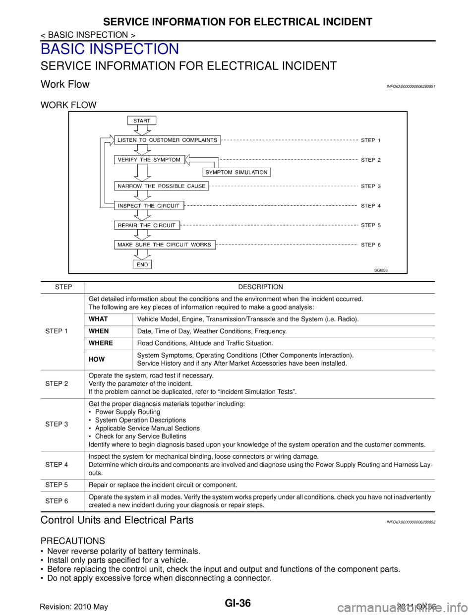
WORK FLOW
Control Units and Electrical PartsINFOID:0000000006280852
PRECAUTIONS
Never reverse polarity of battery terminals.
Install only parts specified for a vehicle.
Before replacing the control unit, check the i nput and output and functions of the component parts.
Do not apply excessive force when disconnecting a connector.
SGI838
STEP DESCRIPTION
STEP 1 Get detailed information about the conditions and the environment when the incident occurred.
The following are key pieces of information required to make a good analysis:
WHAT
Vehicle Model, Engine, Transmission/Transaxle and the System (i.e. Radio).
WHEN Date, Time of Day, Weather Conditions, Frequency.
WHERE Road Conditions, Altitude and Traffic Situation.
HOW System Symptoms, Operating Conditions
(Other Components Interaction).
Service History and if any After Market Accessories have been installed.
STEP 2 Operate the system, road test if necessary.
Verify the parameter of the incident.
If the problem cannot be duplicated, refer to “Incident Simulation Tests”.
STEP 3 Get the proper diagnosis materials together including:
Power Supply Routing
System Operation Descriptions
Applicable Service Manual Sections
Check for any Service Bulletins
Identify where to begin diagnosis based upon your knowledge of the system operation and the customer comments.
STEP 4 Inspect the system for mechanical binding, loose connectors or wiring damage.
Determine which circuits and components are involved and diagnose using the Power Supply Routing and Harness Lay-
outs.
STEP 5 Repair or replace the incident circuit or component.
STEP 6 Operate the system in all modes. Verify the system works properly under all conditions. check you have not inadvertently
created a new incident during your diagnosis or repair steps.
Revision: 2010 May2011 QX56
Page 3271 of 5598
INL-4
< SYSTEM DESCRIPTION >
COMPONENT PARTS
SYSTEM DESCRIPTION
COMPONENT PARTS
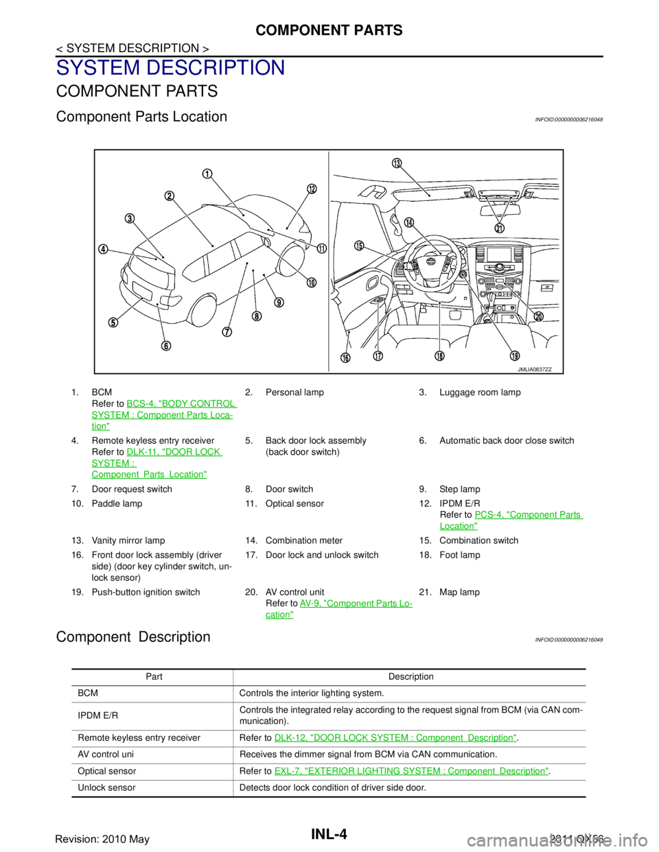
Component Parts LocationINFOID:0000000006216048
Component DescriptionINFOID:0000000006216049
1. BCMRefer to BCS-4, "
BODY CONTROL
SYSTEM : Componen t Parts Loca-
tion"
2. Personal lamp 3. Luggage room lamp
4. Remote keyless entry receiver Refer to DLK-11, "
DOOR LOCK
SYSTEM :
ComponentPartsLocation"
5. Back door lock assembly
(back door switch) 6. Automatic back door close switch
7. Door request switch 8. Door switch 9. Step lamp
10. Paddle lamp 11. Optical sensor 12. IPDM E/R Refer to PCS-4, "
Component Parts
Location"
13. Vanity mirror lamp 14. Combination meter 15. Combination switch
16. Front door lock assembly (driver
side) (door key cylinder switch, un-
lock sensor) 17. Door lock and unlock switch 18. Foot lamp
19. Push-button ignition switch 20. AV control unit Refer to AV- 9 , "
Component Parts Lo-
cation"
21. Map lamp
JMLIA0837ZZ
Part Description
BCM Controls the interior lighting system.
IPDM E/R Controls the integrated relay according to the request signal from BCM (via CAN com-
munication).
Remote keyless entry receiver Refer to DLK-12, "
DOOR LOCK SYSTEM : ComponentDescription".
AV control uni Receives the dimmer signal from BCM via CAN communication.
Optical sensor Refer to EXL-7, "
EXTERIOR LIGHTING SYSTEM : ComponentDescription".
Unlock sensor Detects door lock condition of driver side door.
Revision: 2010 May2011 QX56
Page 3272 of 5598
COMPONENT PARTSINL-5
< SYSTEM DESCRIPTION >
C
DE
F
G H
I
J
K
M A
B
INL
N
O P
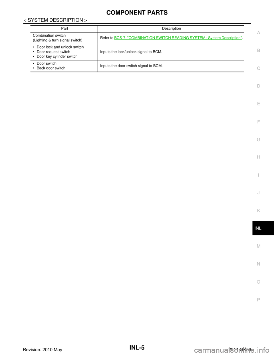
Combination switch
(Lighting & turn signal switch) Refer to
BCS-7, "COMBINATION SWITCH READING SYSTEM : System Description".
Door lock and unlock switch
Door request switch
Door key cylinder switch Inputs the lock/unlock signal to BCM.
Door switch
Back door switch Inputs the door switch signal to BCM.
Part Description
Revision: 2010 May2011 QX56
Page 3273 of 5598
INL-6
< SYSTEM DESCRIPTION >
SYSTEM
SYSTEM
INTERIOR ROOM LAMP CONTROL SYSTEM
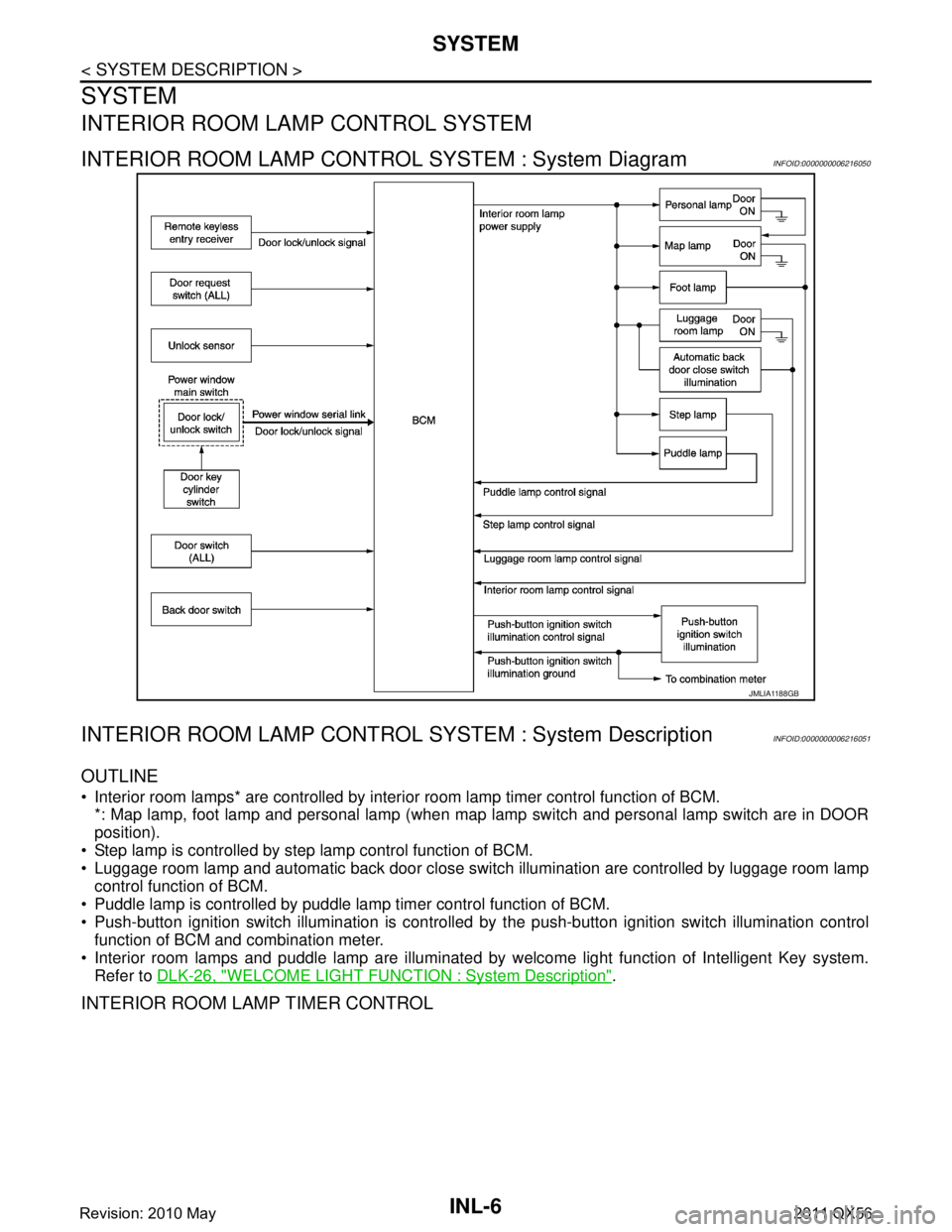
INTERIOR ROOM LAMP CONTROL SYSTEM : System DiagramINFOID:0000000006216050
INTERIOR ROOM LAMP CONTROL SYSTEM : System DescriptionINFOID:0000000006216051
OUTLINE
Interior room lamps* are controlled by interi or room lamp timer control function of BCM.
*: Map lamp, foot lamp and personal lamp (when map lamp switch and personal lamp switch are in DOOR
position).
Step lamp is controlled by step lamp control function of BCM.
Luggage room lamp and automatic back door close switch illumination are controlled by luggage room lamp
control function of BCM.
Puddle lamp is controlled by puddle lamp timer control function of BCM.
Push-button ignition switch illumination is controlled by the push-button ignition switch illumination control
function of BCM and combination meter.
Interior room lamps and puddle lamp are illuminated by welcome light function of Intelligent Key system.
Refer to DLK-26, "
WELCOME LIGHT FUNCTION : System Description".
INTERIOR ROOM LAMP TIMER CONTROL
JMLIA1188GB
Revision: 2010 May2011 QX56
Page 3274 of 5598
SYSTEMINL-7
< SYSTEM DESCRIPTION >
C
DE
F
G H
I
J
K
M A
B
INL
N
O P
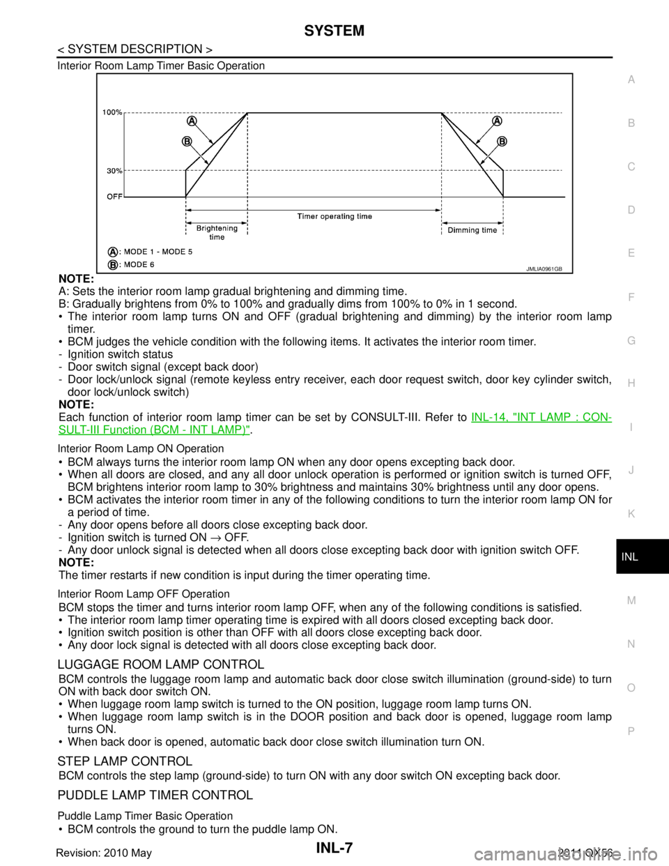
Interior Room Lamp Timer Basic Operation
NOTE:
A: Sets the interior room lamp gradual brightening and dimming time.
B: Gradually brightens from 0% to 100% and gradually dims from 100% to 0% in 1 second.
The interior room lamp turns ON and OFF (gradual brightening and dimming) by the interior room lamp
timer.
BCM judges the vehicle condition with the following items. It activates the interior room timer.
- Ignition switch status
- Door switch signal (except back door)
- Door lock/unlock signal (remote keyless entry receiv er, each door request switch, door key cylinder switch,
door lock/unlock switch)
NOTE:
Each function of interior room lamp ti mer can be set by CONSULT-III. Refer to INL-14, "
INT LAMP : CON-
SULT-III Function (BCM - INT LAMP)".
Interior Room Lamp ON Operation
BCM always turns the interior room lamp ON when any door opens excepting back door.
When all doors are closed, and any all door unlock operation is performed or ignition switch is turned OFF,
BCM brightens interior room lamp to 30% bri ghtness and maintains 30% brightness until any door opens.
BCM activates the interior room timer in any of the fo llowing conditions to turn the interior room lamp ON for
a period of time.
- Any door opens before all doors close excepting back door.
- Ignition switch is turned ON → OFF.
- Any door unlock signal is detected when all doors cl ose excepting back door with ignition switch OFF.
NOTE:
The timer restarts if new condition is input during the timer operating time.
Interior Room Lamp OFF Operation
BCM stops the timer and turns interior room lamp OF F, when any of the following conditions is satisfied.
The interior room lamp timer operating time is expired with all doors closed excepting back door.
Ignition switch position is other than O FF with all doors close excepting back door.
Any door lock signal is detected with all doors close excepting back door.
LUGGAGE ROOM LAMP CONTROL
BCM controls the luggage room lamp and automatic back door close switch illumination (ground-side) to turn
ON with back door switch ON.
When luggage room lamp switch is turned to the ON position, luggage room lamp turns ON.
When luggage room lamp switch is in the DOOR position and back door is opened, luggage room lamp turns ON.
When back door is opened, automatic back door close switch illumination turn ON.
STEP LAMP CONTROL
BCM controls the step lamp (ground-side) to turn ON with any door switch ON excepting back door.
PUDDLE LAMP TIMER CONTROL
Puddle Lamp Timer Basic Operation
BCM controls the ground to turn the puddle lamp ON.
JMLIA0961GB
Revision: 2010 May2011 QX56
Page 3275 of 5598

INL-8
< SYSTEM DESCRIPTION >
SYSTEM
The puddle lamp turns ON and OFF by the puddle lamp timer.
BCM judges the vehicle condition with the following items. It activates the puddle lamp timer.
- Ignition switch status
- Door switch signal (except back door)
- Door lock/unlock signal (remote keyless entry receiver, each door request switch)
- Driver side door lock status
Puddle Lamp ON Operation
BCM activates the puddle lamp timer in any of the following conditions to turn the puddle lamp ON for a period
of time.
Any door opens excepting back door.
Any door opens before all doors close excepting back door.
Ignition switch is turned ON → OFF.
Door unlock signal by remote keyless entry rece iver or each door request switch is detected.
Driver side door is locked*.
NOTE:
The timer restarts if new condition is input during the timer operating time.
Puddle Lamp OFF Operation
BCM stops the timer and turns puddle lamp OFF, when any of the following conditions are satisfied.
The puddle lamp timer operating time is expired.
The interior room lamp OFF conditions.
The interior room lamp timer operating time is expired.
PUSH-BUTTON IGNITION SWITCH ILLUMINATION CONTROL
Push-button Ignition Switch Illumination Basic Operation
BCM controls the ON/OFF status of push-button igni tion switch illumination according to vehicle status.
BCM provides the push-button ignition switch illumi nation control signal and the ground to turn the push-but-
ton ignition switch illumination ON.
BCM cuts the ground supply while each illumination (tai l lamp) is ON. BCM switches to the ground control
according to the meter illumination control function. Refer to MWI-16, "
METER ILLUMINATION CONTROL :
System Description".
Heart Beat Operation
BCM repeats brightening and dimming operation of push-button ignition switch illumination when any of the
following conditions are satisfied.
Welcome light function operates.
When ignition switch is OFF and any of the following conditions are satisfied.
- Driver side door changes from closed to open
- Driver side door changes from locked to unlocked
- Intelligent Key ID comparison is OK and driver side door changes from open to closed
- ID comparison by Intelligent Key transponder is OK
Illumination ON Operation
When ignition switch is not OFF or tail lamp turns ON, push-button ignition switch illumination turns ON.
Dimming Operation
When tail lamp turns OFF and ignition switch is turned OFF, push-button ignition switch illumination dims to
50% brightness.
Illumination OFF Operation
Push-button ignition switch illumination turns OFF when ignition switch turns OFF and tail lamp turns from ON
to OFF, while push-button ignition switch illumination is in ON status.
When push-button ignition switch illumination is at 50% brightness or in heartbeat status, and any of the fol-
lowing conditions are satisfied, push-butt on ignition switch illumination turns OFF.
15 seconds after start of heartbeat operation.
When welcome light function is not operating and any on the following conditions is satisfied.
- Driver side door is closed
- Driver side door is locked
- Intelligent Key ID comparison is NG
- Comparison of Intelligent Key ID by transponder is NG
INTERIOR ROOM LAMP BATTERY SAVER SYSTEM
Revision: 2010 May2011 QX56
Page 3276 of 5598
SYSTEMINL-9
< SYSTEM DESCRIPTION >
C
DE
F
G H
I
J
K
M A
B
INL
N
O P
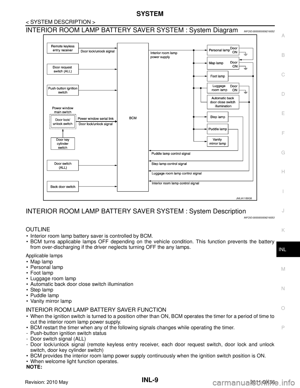
INTERIOR ROOM LAMP BATTERY SAVER SYSTEM : System DiagramINFOID:0000000006216052
INTERIOR ROOM LAMP BATTERY SA VER SYSTEM : System Description
INFOID:0000000006216053
OUTLINE
Interior room lamp battery saver is controlled by BCM.
BCM turns applicable lamps OFF depending on the vehicle condition. This function prevents the battery
from over-discharging if the driver neglects turning OFF the any lamps.
Applicable lamps
Map lamp
Personal lamp
Foot lamp
Luggage room lamp
Automatic back door close switch illumination
Step lamp
Puddle lamp
Vanity mirror lamp
INTERIOR ROOM LAMP BATTERY SAVER FUNCTION
When the ignition switch is turned to a position other than ON, BCM operates the timer for a period of time to
cut the interior room lamp power supply.
BCM restart the timer when any of the following signals changes while operating the timer.
- Push-button ignition switch status
- Door switch signal (ALL)
- Door lock/unlock signal (remote keyless entry re ceiver, each door request switch, door lock and unlock
switch, door key cylinder switch)
BCM provides the interior room lamp power supply continuously when the ignition switch position is ON.
When welcome light function operates.
NOTE:
JMLIA1189GB
Revision: 2010 May2011 QX56
Page 3279 of 5598

INL-12
< SYSTEM DESCRIPTION >
DIAGNOSIS SYSTEM (BCM)
DIAGNOSIS SYSTEM (BCM)
COMMON ITEM
COMMON ITEM : CONSULT-III Function (BCM - COMMON ITEM)INFOID:0000000006368143
APPLICATION ITEM
CONSULT-III performs the following functions via CAN communication with BCM.
SYSTEM APPLICATION
BCM can perform the following functions for each system.
NOTE:
It can perform the diagnosis modes except the following for all sub system selection items.
×: Applicable item
*: This item is indicated, but not used.
FREEZE FRAME DATA (FFD)
The BCM records the following vehicle condition at the time a particular DTC is detected, and displays on
CONSULT-III.
Diagnosis mode Function Description
Work Support Changes the setting for each system function.
Self Diagnostic Result Displays the diagnosis results judged by BCM. Refer to BCS-57, "
DTCIndex".
CAN Diag Support Monitor Monitors the reception status of CAN communication viewed from BCM. Refer to CONSULT-III opera-
tion manual.
Data Monitor The BCM input/output signals are displayed.
Active Test The signals used to activate ea ch device are forcibly supplied from BCM.
Ecu Identification The BCM part number is displayed.
Configuration Read and save the vehicle specification.
Write the vehicle specification when replacing BCM.
System Sub system selection item Diagnosis mode
Work Support Data Monitor Active Test
Door lock DOOR LOCK ×××
Rear window defogger REAR DEFOGGER ××
Warning chime BUZZER ××
Interior room lamp timer INT LAMP ×××
Exterior lamp HEAD LAMP ×××
Wiper and washer WIPER ×××
Turn signal and hazard warning lamps FLASHER ×××
— AIR CONDITONER* ××
Intelligent Key system
Engine start system INTELLIGENT KEY
×××
Combination switch COMB SW ×
Body control system BCM ×
IVIS IMMU ×××
Interior room lamp battery saver BATTERY SAVER ×××
Back door TRUNK ×
Vehicle security system THEFT ALM ×××
RAP system RETAINED PWR ×
Signal buffer system SIGNAL BUFFER ××
Revision: 2010 May2011 QX56