2011 INFINITI QX56 key
[x] Cancel search: keyPage 2628 of 5598
EM-66
< REMOVAL AND INSTALLATION >
TIMING CHAIN
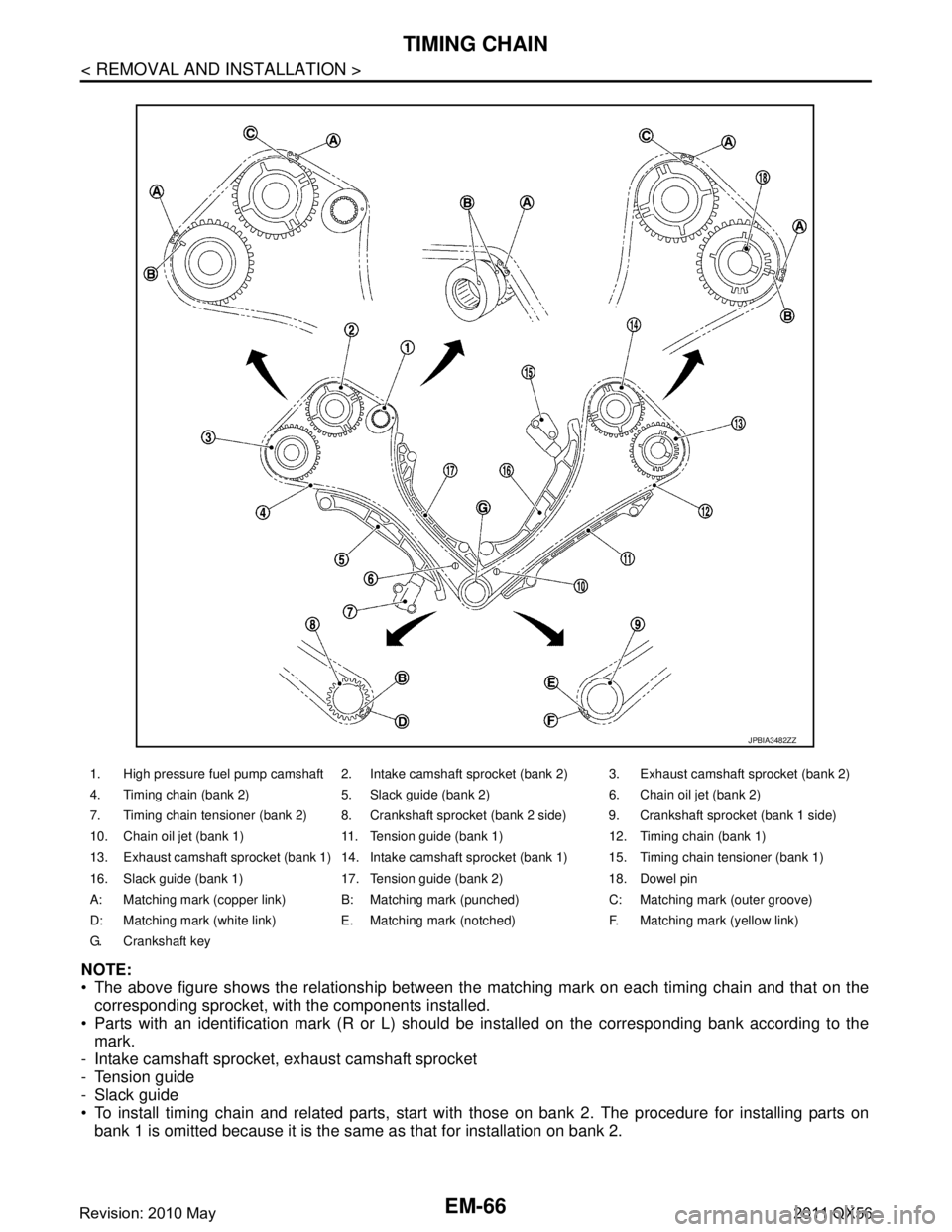
NOTE:
The above figure shows the relationship between the matching mark on each timing chain and that on the
corresponding sprocket, with the components installed.
Parts with an identification mark (R or L) should be installed on the corresponding bank according to the
mark.
- Intake camshaft sprocket, exhaust camshaft sprocket
- Tension guide
- Slack guide
To install timing chain and related parts, start with those on bank 2. The procedure for installing parts on
bank 1 is omitted because it is the same as that for installation on bank 2.
1. High pressure fuel pump camshaft 2. Intake camshaft sprocket (bank 2) 3. Exhaust camshaft sprocket (bank 2)
4. Timing chain (bank 2) 5. Slack guide (bank 2) 6. Chain oil jet (bank 2)
7. Timing chain tensioner (bank 2) 8. Crankshaft sprocket (bank 2 side) 9. Crankshaft sprocket (bank 1 side)
10. Chain oil jet (bank 1) 11. Tension guide (bank 1) 12. Timing chain (bank 1)
13. Exhaust camshaft sprocket (bank 1) 14. Intake camshaft sprocket (bank 1) 15. Timing chain tensioner (bank 1)
16. Slack guide (bank 1) 17. Tension guide (bank 2) 18. Dowel pin
A: Matching mark (copper link) B: Matching mark (punched) C: Matching mark (outer groove)
D: Matching mark (white link) E. Matching mark (notched) F. Matching mark (yellow link)
G. Crankshaft key
JPBIA3482ZZ
Revision: 2010 May2011 QX56
Page 2629 of 5598
TIMING CHAINEM-67
< REMOVAL AND INSTALLATION >
C
DE
F
G H
I
J
K L
M A
EM
NP
O
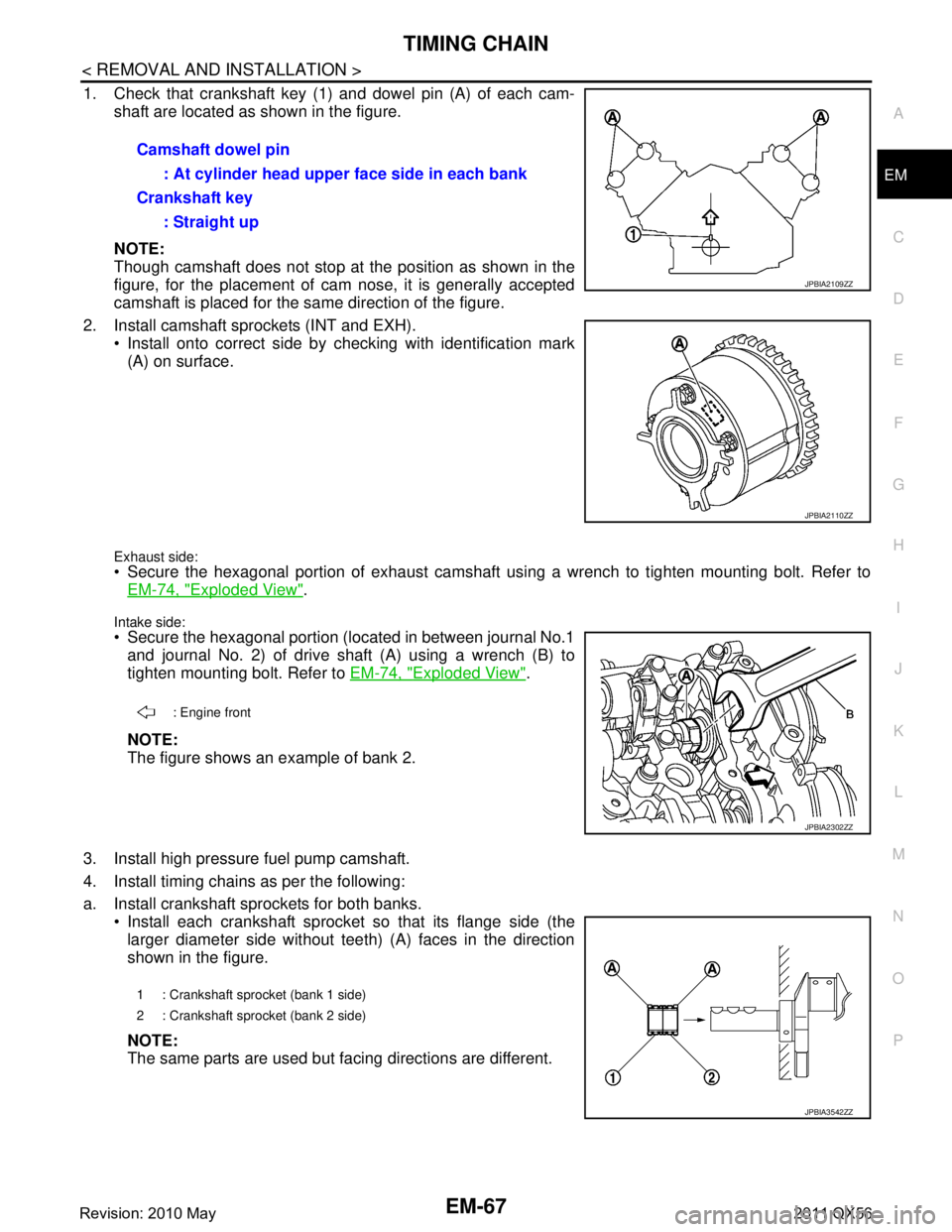
1. Check that crankshaft key (1) and dowel pin (A) of each cam-
shaft are located as shown in the figure.
NOTE:
Though camshaft does not stop at the position as shown in the
figure, for the placement of cam nose, it is generally accepted
camshaft is placed for the same direction of the figure.
2. Install camshaft sprockets (INT and EXH). Install onto correct side by checking with identification mark(A) on surface.
Exhaust side: Secure the hexagonal portion of exhaust camshaft using a wrench to tighten mounting bolt. Refer toEM-74, "
Exploded View".
Intake side:
Secure the hexagonal portion (located in between journal No.1and journal No. 2) of drive shaft (A) using a wrench (B) to
tighten mounting bolt. Refer to EM-74, "
Exploded View".
NOTE:
The figure shows an example of bank 2.
3. Install high pressure fuel pump camshaft.
4. Install timing chains as per the following:
a. Install crankshaft sprockets for both banks. Install each crankshaft sprocket so that its flange side (thelarger diameter side without teeth) (A) faces in the direction
shown in the figure.
NOTE:
The same parts are used but facing directions are different.Camshaft dowel pin
: At cylinder head upper face side in each bank
Crankshaft key : Straight up
JPBIA2109ZZ
JPBIA2110ZZ
: Engine front
JPBIA2302ZZ
1 : Crankshaft sprocket (bank 1 side)
2 : Crankshaft sprocket (bank 2 side)
JPBIA3542ZZ
Revision: 2010 May2011 QX56
Page 2668 of 5598
EM-106
< UNIT DISASSEMBLY AND ASSEMBLY >
CYLINDER BLOCK
CYLINDER BLOCK
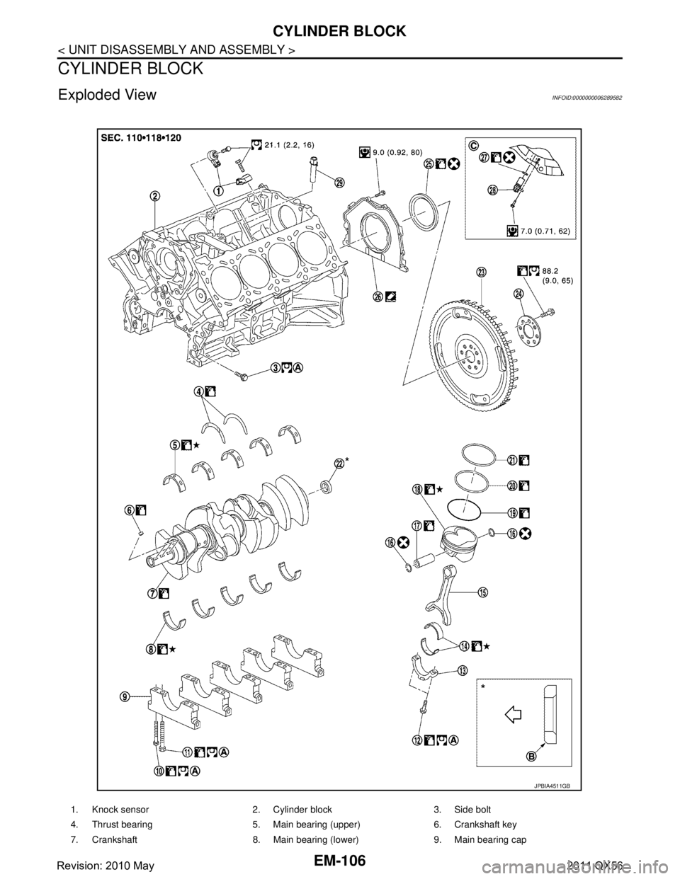
Exploded ViewINFOID:0000000006289582
1. Knock sensor 2. Cylinder block 3. Side bolt
4. Thrust bearing 5. Main bearing (upper) 6. Crankshaft key
7. Crankshaft 8. Main bearing (lower) 9. Main bearing cap
JPBIA4511GB
Revision: 2010 May2011 QX56
Page 2732 of 5598
![INFINITI QX56 2011 Factory Service Manual
EXL-22
< SYSTEM DESCRIPTION >[XENON TYPE]
DIAGNOSIS SYSTEM (BCM)
DIAGNOSIS SYSTEM (BCM)
COMMON ITEM
COMMON ITEM : CONSULT-III Fu
nction (BCM - COMMON ITEM)INFOID:0000000006368037
APPLICATION ITEM
CON INFINITI QX56 2011 Factory Service Manual
EXL-22
< SYSTEM DESCRIPTION >[XENON TYPE]
DIAGNOSIS SYSTEM (BCM)
DIAGNOSIS SYSTEM (BCM)
COMMON ITEM
COMMON ITEM : CONSULT-III Fu
nction (BCM - COMMON ITEM)INFOID:0000000006368037
APPLICATION ITEM
CON](/manual-img/42/57033/w960_57033-2731.png)
EXL-22
< SYSTEM DESCRIPTION >[XENON TYPE]
DIAGNOSIS SYSTEM (BCM)
DIAGNOSIS SYSTEM (BCM)
COMMON ITEM
COMMON ITEM : CONSULT-III Fu
nction (BCM - COMMON ITEM)INFOID:0000000006368037
APPLICATION ITEM
CONSULT-III performs the following functions via CAN communication with BCM.
SYSTEM APPLICATION
BCM can perform the following functions for each system.
NOTE:
It can perform the diagnosis modes except the following for all sub system selection items.
×: Applicable item
*: This item is indicated, but not used.
FREEZE FRAME DATA (FFD)
The BCM records the following vehicle condition at the time a particular DTC is detected, and displays on
CONSULT-III.
Diagnosis mode Function Description
Work Support Changes the setting for each system function.
Self Diagnostic Result Displays the diagnosis results judged by BCM. Refer to BCS-57, "
DTCIndex".
CAN Diag Support Monitor Monitors the reception status of CAN communication viewed from BCM. Refer to CONSULT-III opera-
tion manual.
Data Monitor The BCM input/output signals are displayed.
Active Test The signals used to activate ea ch device are forcibly supplied from BCM.
Ecu Identification The BCM part number is displayed.
Configuration Read and save the vehicle specification.
Write the vehicle specification when replacing BCM.
System Sub system selection item Diagnosis mode
Work Support Data Monitor Active Test
Door lock DOOR LOCK ×××
Rear window defogger REAR DEFOGGER ××
Warning chime BUZZER ××
Interior room lamp timer INT LAMP ×××
Exterior lamp HEAD LAMP ×××
Wiper and washer WIPER ×××
Turn signal and hazard warning lamps FLASHER ×××
— AIR CONDITONER* ××
Intelligent Key system
Engine start system INTELLIGENT KEY
×××
Combination switch COMB SW ×
Body control system BCM ×
IVIS IMMU ×××
Interior room lamp battery saver BATTERY SAVER ×××
Back door TRUNK ×
Vehicle security system THEFT ALM ×××
RAP system RETAINED PWR ×
Signal buffer system SIGNAL BUFFER ××
Revision: 2010 May2011 QX56
Page 2736 of 5598
![INFINITI QX56 2011 Factory Service Manual
EXL-26
< SYSTEM DESCRIPTION >[XENON TYPE]
DIAGNOSIS SYSTEM (BCM)
*: Factory setting
DATA MONITOR
ACTIVE TEST
Service item Setting item Setting
HAZARD ANSWER
BACK Lock Only With locking only
Sets the INFINITI QX56 2011 Factory Service Manual
EXL-26
< SYSTEM DESCRIPTION >[XENON TYPE]
DIAGNOSIS SYSTEM (BCM)
*: Factory setting
DATA MONITOR
ACTIVE TEST
Service item Setting item Setting
HAZARD ANSWER
BACK Lock Only With locking only
Sets the](/manual-img/42/57033/w960_57033-2735.png)
EXL-26
< SYSTEM DESCRIPTION >[XENON TYPE]
DIAGNOSIS SYSTEM (BCM)
*: Factory setting
DATA MONITOR
ACTIVE TEST
Service item Setting item Setting
HAZARD ANSWER
BACK Lock Only With locking only
Sets the hazard warning lamp answer back function
when the door is lock/unlock with the request switch or
the key fob.
Unlk Only With unlocking only
Lock&Unlk
*With locking/unlocking
Off Without the function
Monitor item [Unit] Description
REQ SW-DR
[On/Off] The switch status input from the request switch (driver side)
REQ SW-AS
[On/Off] The switch status input from the request switch (passenger side)
PUSH SW
[On/Off] The switch status input from the push-button ignition switch
TURN SIGNAL R
[On/Off] Each switch status that BCM detects from the combination switch reading function
TURN SIGNAL L
[On/Off]
HAZARD SW
[On/Off] The switch status input from the hazard switch
RKE-LOCK
[On/Off] Lock signal status received from the remote keyless entry receiver
RKE-UNLOCK
[On/Off] Unlock signal status received from the remote keyless entry receiver
RKE-PANIC
[On/Off] Panic alarm signal status received from the remote keyless entry receiver
Test item Operation Description
FLASHER RH Outputs the voltage to blink the right side turn signal lamps.
LH Outputs the voltage to blink the left side turn signal lamps.
Off Stops the voltage to turn the turn signal lamps OFF.
Revision: 2010 May2011 QX56
Page 2965 of 5598
GI-1
GENERAL INFORMATION
C
DE
F
G H
I
J
K L
M B
GI
SECTION GI
N
O P
CONTENTS
GENERAL INFORMATION
HOW TO USE THIS MANU AL ......................3
HOW TO USE THIS MANUAL ....................... .....3
Description .......................................................... ......3
Terms ........................................................................3
Units ..........................................................................3
Contents ....................................................................3
Relation between Illustrations and Descriptions .......4
Components ..............................................................4
HOW TO FOLLOW TROUBLE DIAGNOSES .....6
Description ................................................................6
How to Follow Test Groups in Trouble Diagnosis ......6
Key to Symbols Signifying Measurements or Pro-
cedures ............................................................... ......
7
HOW TO READ WIRING DIAGRAMS ................9
Connector Symbols ............................................. ......9
Sample/Wiring Diagram -Example- .........................10
Connector Information .............................................12
ABBREVIATIONS .......................................... ....14
Abbreviation List .................................................. ....14
TIGHTENING TORQUE OF STANDARD
BOLTS ................................................................
19
Description .......................................................... ....19
Tightening Torque Table (New Standard Includ-
ed) ...........................................................................
19
RECOMMENDED CHEMICAL PRODUCTS
AND SEALANTS ................................................
22
Recommended Chemical Products and Sealants ....22
VEHICLE INFORMATION ............................23
IDENTIFICATION INFORMATION ................. ....23
Model Variation ................................................... ....23
Information About Identification or Model Code ......23
Dimensions .............................................................25
Wheels & Tires ........................................................25
PRECAUTION ..............................................26
PRECAUTIONS .................................................26
Description ........................................................... ....26
Precaution for Supplemental Restraint System
(SRS) "AIR BAG" and "SEAT BELT PRE-TEN-
SIONER" .................................................................
26
Precautions For Xenon Headlamp Service .............26
Precaution Necessary for Steering Wheel Rota-
tion after Battery Disconnect ...................................
27
Precaution for Procedure without Cowl Top Cover ....27
General Precautions ................................................27
Three Way Catalyst .................................................29
Multiport Fuel Injection System or Engine Control
System .....................................................................
29
Hoses ......................................................................29
Engine Oils ..............................................................30
Air Conditioning .......................................................31
Fuel ..........................................................................31
LIFTING POINT .................................................32
Pantograph Jack ......................................................32
Garage Jack and Safety Stand ................................32
2-Pole Lift ................................................................33
TOW TRUCK TOWING .....................................34
Tow Truck Towing ...................................................34
Vehicle Recovery (Freeing a Stuck Vehicle) ...........34
BASIC INSPECTION ...................................36
SERVICE INFORMATION FOR ELECTRICAL
INCIDENT ..........................................................
36
Work Flow ............................................................ ....36
Control Units and Electrical Parts ............................36
How to Check Terminal ...........................................37
Intermittent Incident .................................................40
Circuit Inspection .....................................................43
CONSULT-III/GST CHECKING SYSTEM .........48
Description ...............................................................48
CONSULT-III Function and System Application*1 ....48
Revision: 2010 May2011 QX56
Page 2971 of 5598
HOW TO FOLLOW TROUBLE DIAGNOSES
GI-7
< HOW TO USE THIS MANUAL >
C
D E
F
G H
I
J
K L
M B
GI
N
O P
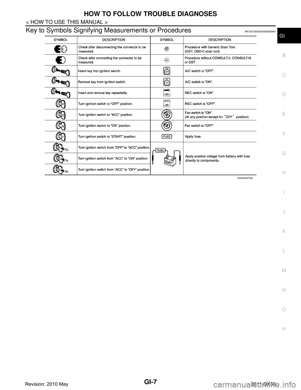
Key to Symbols Signifying M easurements or ProceduresINFOID:0000000006280843
JPAIA0397GB
Revision: 2010 May2011 QX56
Page 2993 of 5598
PRECAUTIONSGI-29
< PRECAUTION >
C
DE
F
G H
I
J
K L
M B
GI
N
O P
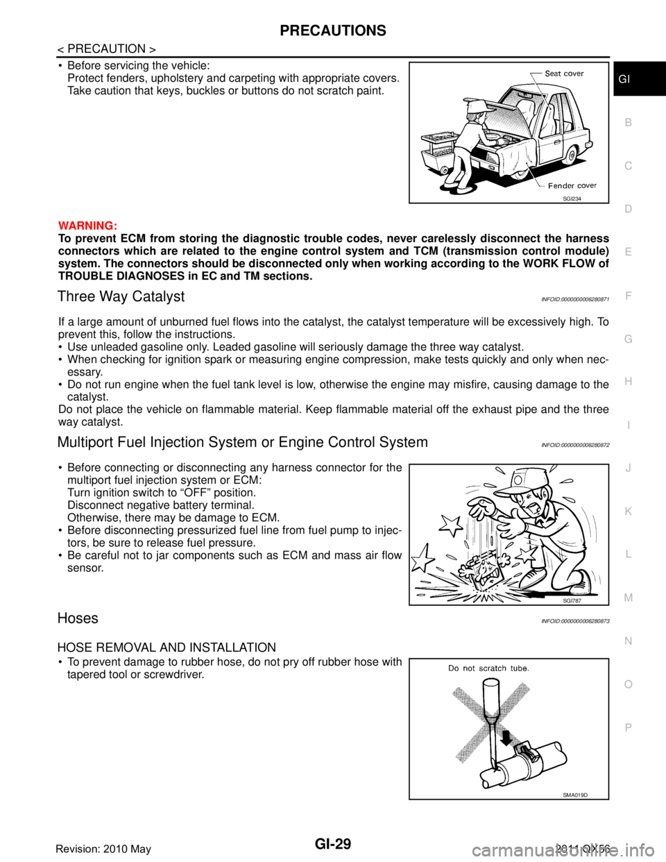
Before servicing the vehicle: Protect fenders, upholstery and carpeting with appropriate covers.
Take caution that keys, buckles or buttons do not scratch paint.
WARNING:
To prevent ECM from storing the diagnostic trou ble codes, never carelessly disconnect the harness
connectors which are related to the engine cont rol system and TCM (transmission control module)
system. The connectors should be disconnected only when working according to the WORK FLOW of
TROUBLE DIAGNOSES in EC and TM sections.
Three Way CatalystINFOID:0000000006280871
If a large amount of unburned fuel flows into the catalyst , the catalyst temperature will be excessively high. To
prevent this, follow the instructions.
Use unleaded gasoline only. Leaded gasoline will seriously damage the three way catalyst.
When checking for ignition spark or measuring engine compression, make tests quickly and only when nec- essary.
Do not run engine when the fuel tank level is low, otherwise the engine may misfire, causing damage to the
catalyst.
Do not place the vehicle on flammable material. Keep flammable material off the exhaust pipe and the three
way catalyst.
Multiport Fuel Inje ction System or Engine Control SystemINFOID:0000000006280872
Before connecting or disconnecti ng any harness connector for the
multiport fuel injection system or ECM:
Turn ignition switch to “OFF” position.
Disconnect negative battery terminal.
Otherwise, there may be damage to ECM.
Before disconnecting pressurized fuel line from fuel pump to injec- tors, be sure to release fuel pressure.
Be careful not to jar components such as ECM and mass air flow sensor.
HosesINFOID:0000000006280873
HOSE REMOVAL AND INSTALLATION
To prevent damage to rubber hose, do not pry off rubber hose withtapered tool or screwdriver.
SGI234
SGI787
SMA019D
Revision: 2010 May2011 QX56