2011 INFINITI QX56 dimensions
[x] Cancel search: dimensionsPage 2652 of 5598
![INFINITI QX56 2011 Factory Service Manual
EM-90
< REMOVAL AND INSTALLATION >
CYLINDER HEAD
b. Drive out valve guide (EXH) with a press [under a 20 kN (2 ton,2.2 US ton, 2.0 lmp ton) pressure] or a hammer and the valve
guide drift (commercial INFINITI QX56 2011 Factory Service Manual
EM-90
< REMOVAL AND INSTALLATION >
CYLINDER HEAD
b. Drive out valve guide (EXH) with a press [under a 20 kN (2 ton,2.2 US ton, 2.0 lmp ton) pressure] or a hammer and the valve
guide drift (commercial](/manual-img/42/57033/w960_57033-2651.png)
EM-90
< REMOVAL AND INSTALLATION >
CYLINDER HEAD
b. Drive out valve guide (EXH) with a press [under a 20 kN (2 ton,2.2 US ton, 2.0 lmp ton) pressure] or a hammer and the valve
guide drift (commercial service tool).
WARNING:
Cylinder head contains heat . When working, wear protec-
tive equipment to avo id getting burned.
ASSEMBLY
1. Install valve guide (EXH), if removed.
Replace with oversized [0.2 mm (0.008 in)] valve guide (EXH).
a. Using the valve guide reamer (commercial service tool) (A), ream cylinder head valve guide (EXH) hole.
b. Heat cylinder head to 110 to 130 °C (230 to 266 °F) by soaking in
heated oil (A).
c. Using the valve guide drift (commercial service tool), press valve guide (EXH) from camshaft side to the dimensions as shown in
the figure.
WARNING:
Cylinder head contains heat . When working, wear protec-
tive equipment to avo id getting burned.
SEM931C
Oversize (service) [0.2 mm (0.008 in)]:
: Refer to EM-135, "
CylinderHead".
JPBIA0185ZZ
JPBIA0184ZZ
Projection (A)
: Refer to EM-135, "
CylinderHead".
JPBIA0186ZZ
Revision: 2010 May2011 QX56
Page 2653 of 5598
CYLINDER HEADEM-91
< REMOVAL AND INSTALLATION >
C
DE
F
G H
I
J
K L
M A
EM
NP
O
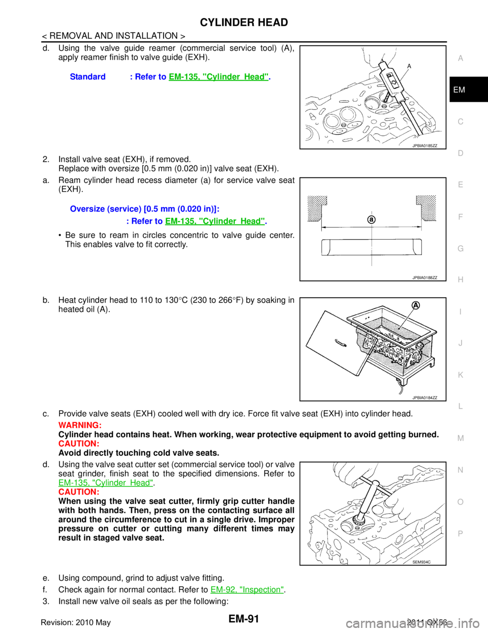
d. Using the valve guide reamer (commercial service tool) (A),
apply reamer finish to valve guide (EXH).
2. Install valve seat (EXH), if removed. Replace with oversize [0.5 mm (0.020 in)] valve seat (EXH).
a. Ream cylinder head recess diameter (a) for service valve seat (EXH).
Be sure to ream in circles concentric to valve guide center.
This enables valve to fit correctly.
b. Heat cylinder head to 110 to 130 °C (230 to 266 °F) by soaking in
heated oil (A).
c. Provide valve seats (EXH) cooled well with dry ice. Force fit valve seat (EXH) into cylinder head. WARNING:
Cylinder head contains heat. When working, w ear protective equipment to avoid getting burned.
CAUTION:
Avoid directly touching cold valve seats.
d. Using the valve seat cutter set (commercial service tool) or valve seat grinder, finish seat to the specified dimensions. Refer to
EM-135, "
CylinderHead".
CAUTION:
When using the valve seat cutt er, firmly grip cutter handle
with both hands. Then, press on the contacting surface all
around the circumference to cu t in a single drive. Improper
pressure on cutter or cutting many different times may
result in staged valve seat.
e. Using compound, grind to adjust valve fitting.
f. Check again for normal contact. Refer to EM-92, "
Inspection".
3. Install new valve oil seals as per the following: Standard : Refer to
EM-135, "
CylinderHead".
JPBIA0185ZZ
Oversize (service) [0.5 mm (0.020 in)]:
: Refer to EM-135, "
CylinderHead".
JPBIA0188ZZ
JPBIA0184ZZ
SEM934C
Revision: 2010 May2011 QX56
Page 2655 of 5598
CYLINDER HEADEM-93
< REMOVAL AND INSTALLATION >
C
DE
F
G H
I
J
K L
M A
EM
NP
O
Cylinder Head Distortion
NOTE:
When performing this inspection, cylinder block distortion should be also checked. Refer to
EM-115, "
Inspec-
tion".
1. Using a scraper, wipe out oil, scale, gasket, s ealant and carbon deposits from surface of cylinder head.
CAUTION:
Never allow gasket fragments to enter engine oil or engine coolant passages.
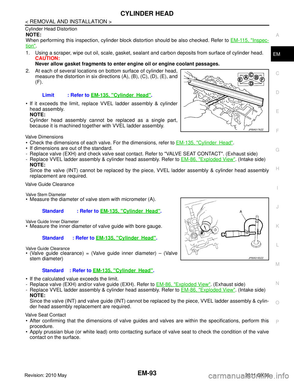
2. At each of several locations on bottom surface of cylinder head, measure the distortion in six directi ons (A), (B), (C), (D), (E), and
(F).
If it exceeds the limit, replace VVEL ladder assembly & cylinder head assembly.
NOTE:
Cylinder head assembly cannot be replaced as a single part,
because it is machined together with VVEL ladder assembly.
Valve Dimensions
Check the dimensions of each valv e. For the dimensions, refer to EM-135, "CylinderHead".
If dimensions are out of the standard.
- Replace valve (EXH) and check valve seat contact. Refer to "VALVE SEAT CONTACT". (Exhaust side)
- Replace VVEL ladder assembly & cylinder head assembly. Refer to EM-86, "
Exploded View". (Intake side)
NOTE:
Since the valve (INT) cannot be replaced by the pi ece, VVEL ladder assembly & cylinder head assembly
replacement are required.
Valve Guide Clearance
Valve Stem Diameter
Measure the diameter of valve stem with micrometer (A).
Valve Guide Inner Diameter
Measure the inner diameter of valve guide with bore gauge.
Valve Guide Clearance
(Valve guide clearance) = (Valve guide inner diameter) – (Valve
stem diameter)
If the calculated value exceeds the limit.
- Replace valve (EXH) and/or valve guide (EXH). Refer to EM-86, "
Exploded View". (Exhaust side)
- Replace VVEL ladder assembly & cylinder head assembly. Refer to EM-86, "
Exploded View". (Intake side)
NOTE:
Since the valve (INT) and valve guide (INT) cannot be repl aced by the piece, VVEL ladder assembly & cylin-
der head assembly replacement are required.
Valve Seat Contact
After confirming that the dimensions of valve guides and valves are within the specifications, perform this
procedure.
Apply prussian blue (or white lead) onto contacting surfac e of valve seat to check the condition of the valve
contact on the surface. Limit : Refer to
EM-135, "
CylinderHead".
JPBIA0176ZZ
Standard : Refer to EM-135, "CylinderHead".
Standard : Refer to EM-135, "
CylinderHead".
Standard : Refer to EM-135, "
CylinderHead".
JPBIA0183ZZ
Revision: 2010 May2011 QX56
Page 2656 of 5598

EM-94
< REMOVAL AND INSTALLATION >
CYLINDER HEAD
Check if the contact area band is continuous all around the circum-ference.
- If not, grind to adjust valve fitting and check again. If the contacting surface still has “NG” conditions even after the re-check, replace
valve seat (EXH). Refer to EM-86, "
Exploded View". (Exhaust
side)
- If not, replace VVEL ladder assembly & cylinder head assembly. Refer to EM-86, "
Exploded View". (Intake side)
NOTE:
Since the valve seat (INT) cannot be replaced by t he piece, VVEL ladder assembly & cylinder head assem-
bly replacement are required.
Valve Spring (with valve spring seat) Squareness
Set a try square (A) along the side of valve spring (with valve
spring seat) and rotate spring. Measure the maximum clearance
between the top of spring and try square.
If it exceeds the limit.
- Replace valve spring (with valve spring seat) (EXH). Refer to EM-
86, "Exploded View". (Exhaust side)
- Replace VVEL ladder assembly & cylinder head assembly. Refer
to EM-86, "
Exploded View". (Intake side)
NOTE:
Since the valve spring (with valve spring seat) (INT) c annot be replaced by the piece, VVEL ladder assembly
& cylinder head assembly replacement are required.
Valve Spring Dimensions and Valve Spring Pressure Load
Check the valve spring (with valve spring seat) pressure at speci- fied spring height.
If the installation load or load with valve open is out of the stan- dard.
- Replace valve spring (with valve spring seat) (EXH). Refer to EM-
86, "Exploded View". (Exhaust side)
- Replace VVEL ladder assembly & cylinder head assembly. Refer to EM-86, "
Exploded View". (Intake side)
NOTE:
Since the valve spring (with valve spring seat) (INT) c annot be replaced by the piece, VVEL ladder assembly
& cylinder head assembly replacement are required.
INSPECTION AFTER ASSEMBLY
Inspection for Leakage
The following are procedures for checking fluid leakage, lubricant leakage.
Before starting engine, check oil/fluid levels includi ng engine coolant and engine oil. If any are less than the
required quantity, fill them to the specified level. Refer to MA-10, "
Fluids and Lubricants".
Follow the procedure below to check for fuel leakage.
- Turn ignition switch to the “ON” position (with engi ne stopped). With fuel pressure applied to fuel piping,
check for fuel leakage at connection points.
- Start engine. With engine speed increased, che ck again for fuel leakage at connection points.
Run engine to check for unusual noise and vibration. NOTE:
A: OK
B: NG
JPBIA0187ZZ
B : Contact
Limit : Refer to EM-135, "CylinderHead".
JPBIA0189ZZ
Standard
: Refer to EM-135, "
CylinderHead".
SEM113
Revision: 2010 May2011 QX56
Page 2683 of 5598
CYLINDER BLOCKEM-121
< UNIT DISASSEMBLY AND ASSEMBLY >
C
DE
F
G H
I
J
K L
M A
EM
NP
O
If out of the standard, measure the main bearing
oil clearance. Then use undersize bearing. Refer to EM-
128, "MainBearing".
CRANKSHAFT PIN JOURNAL DIAMETER
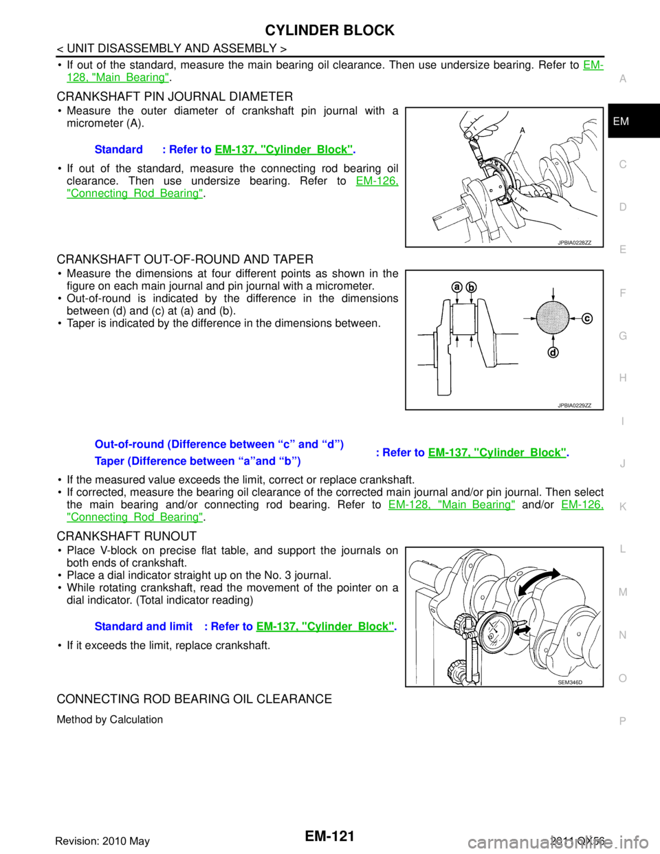
Measure the outer diameter of crankshaft pin journal with a
micrometer (A).
If out of the standard, measure the connecting rod bearing oil clearance. Then use undersize bearing. Refer to EM-126,
"ConnectingRodBearing".
CRANKSHAFT OUT-OF-ROUND AND TAPER
Measure the dimensions at four different points as shown in the
figure on each main journal and pin journal with a micrometer.
Out-of-round is indicated by t he difference in the dimensions
between (d) and (c) at (a) and (b).
Taper is indicated by the difference in the dimensions between.
If the measured value exceeds the li mit, correct or replace crankshaft.
If corrected, measure the bearing oil clearance of the corrected main journal and/or pin journal. Then select
the main bearing and/or connecting rod bearing. Refer to EM-128, "
MainBearing" and/or EM-126,
"ConnectingRodBearing".
CRANKSHAFT RUNOUT
Place V-block on precise flat table, and support the journals on
both ends of crankshaft.
Place a dial indicator straight up on the No. 3 journal.
While rotating crankshaft, read the movement of the pointer on a
dial indicator. (Total indicator reading)
If it exceeds the limit, replace crankshaft.
CONNECTING ROD BEARING OIL CLEARANCE
Method by Calculation
Standard : Refer to EM-137, "CylinderBlock".
JPBIA0228ZZ
JPBIA0229ZZ
Out-of-round (Difference between “c” and “d”)
: Refer to EM-137, "CylinderBlock".
Taper (Difference between “a”and “b”)
Standard and limit : Refer to EM-137, "
CylinderBlock".
SEM346D
Revision: 2010 May2011 QX56
Page 2685 of 5598
CYLINDER BLOCKEM-123
< UNIT DISASSEMBLY AND ASSEMBLY >
C
DE
F
G H
I
J
K L
M A
EM
NP
O
Cut a plastigage slightly shorter than the bearing width,
and place it in crankshaft axial direction, avoiding oil
holes.
Install main bearing to cylinder block and main bearing cap, and tighten main bearing cap bolts with main
bearing cap to the specified torque. Refer to EM-107, "
Disassembly and Assembly" for the tightening proce-
dure.
CAUTION:
Never rotate crankshaft.
Remove main bearing cap and bearings, and using the scale on the plastigage bag, measure the plastigage width.
NOTE:
The procedure when the measured value exceeds the limit is the
same as that described in the “Method by Calculation”.
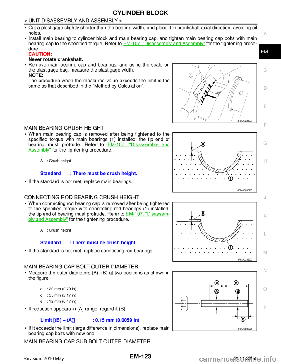
MAIN BEARING CRUSH HEIGHT
When main bearing cap is removed after being tightened to thespecified torque with main bearings (1) installed, the tip end of
bearing must protrude. Refer to EM-107, "
Disassembly and
Assembly" for the tightening procedure.
If the standard is not met, replace main bearings.
CONNECTING ROD BEARING CRUSH HEIGHT
When connecting rod bearing cap is removed after being tightened to the specified torque with connecting rod bearings (1) installed,
the tip end of bearing must protrude. Refer to EM-107, "
Disassem-
bly and Assembly" for the tightening procedure.
If the standard is not met, replace connecting rod bearings.
MAIN BEARING CAP BOLT OUTER DIAMETER
Measure the outer diameters (A), (B) at two positions as shown in
the figure.
If reduction appears in (A) range, regard it (B).
If it exceeds the limit (large difference in dimensions), replace main bearing cap bolts with new one.
MAIN BEARING CAP SUB BOLT OUTER DIAMETER
JPBIA0231ZZ
A : Crush height
Standard : There must be crush height.
JPBIA0233ZZ
A : Crush height
Standard : There must be crush height.
JPBIA0233ZZ
c : 20 mm (0.79 in)
d : 55 mm (2.17 in)
e : 12 mm (0.47 in)
Limit [(B) – (A)] : 0.15 mm (0.0059 in)
JPBIA2280ZZ
Revision: 2010 May2011 QX56
Page 2686 of 5598
EM-124
< UNIT DISASSEMBLY AND ASSEMBLY >
CYLINDER BLOCK
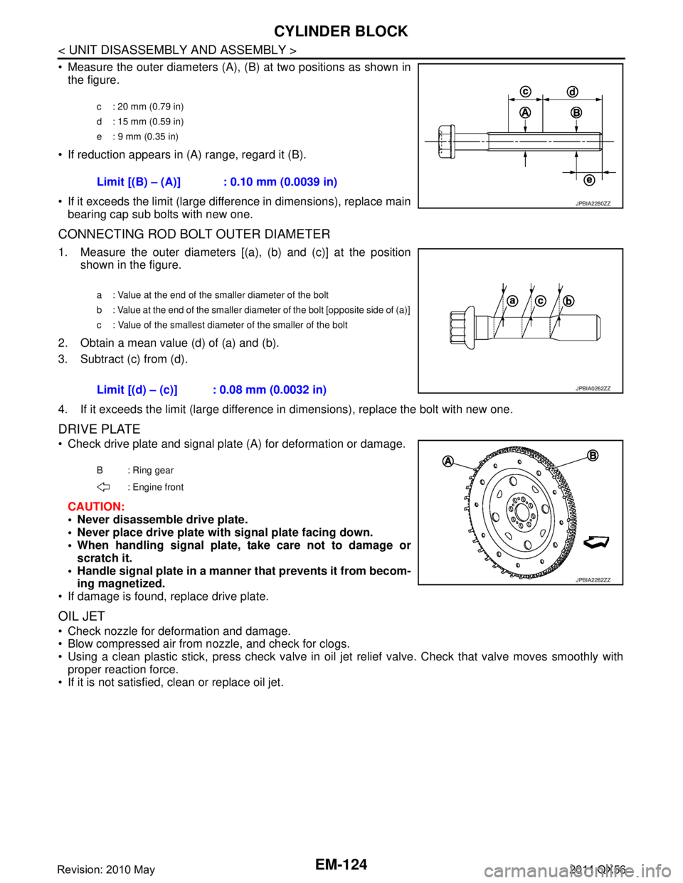
Measure the outer diameters (A), (B) at two positions as shown in
the figure.
If reduction appears in (A) range, regard it (B).
If it exceeds the limit (large difference in dimensions), replace main bearing cap sub bolts with new one.
CONNECTING ROD BOLT OUTER DIAMETER
1. Measure the outer diameters [(a), (b) and (c)] at the position shown in the figure.
2. Obtain a mean value (d) of (a) and (b).
3. Subtract (c) from (d).
4. If it exceeds the limit (large difference in dimensions), replace the bolt with new one.
DRIVE PLATE
Check drive plate and signal plate (A) for deformation or damage.
CAUTION:
Never disassemble drive plate.
Never place drive plate with signal plate facing down.
When handling signal plate, take care not to damage or scratch it.
Handle signal plate in a manner that prevents it from becom-
ing magnetized.
If damage is found, replace drive plate.
OIL JET
Check nozzle for deformation and damage.
Blow compressed air from nozzle, and check for clogs.
Using a clean plastic stick, press check valve in oil je t relief valve. Check that valve moves smoothly with
proper reaction force.
If it is not satisfied, clean or replace oil jet.
c : 20 mm (0.79 in)
d : 15 mm (0.59 in)
e : 9 mm (0.35 in)
Limit [(B) – (A)] : 0.10 mm (0.0039 in)
JPBIA2280ZZ
a : Value at the end of the smaller diameter of the bolt
b : Value at the end of the smaller diameter of the bolt [opposite side of (a)]
c : Value of the smallest diameter of the smaller of the bolt
Limit [(d) – (c)] : 0.08 mm (0.0032 in)JPBIA0262ZZ
B : Ring gear
: Engine front
JPBIA2282ZZ
Revision: 2010 May2011 QX56
Page 2697 of 5598
SERVICE DATA AND SPECIFICATIONS (SDS)
EM-135
< SERVICE DATA AND SPECIFICATIONS (SDS)
C
D E
F
G H
I
J
K L
M A
EM
NP
O
Cylinder HeadINFOID:0000000006289594
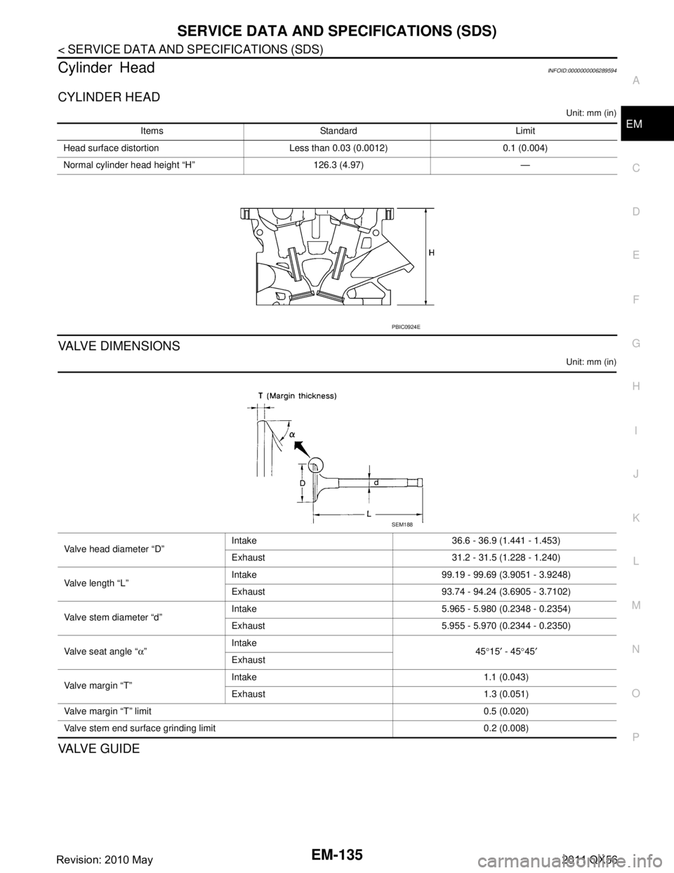
CYLINDER HEAD
Unit: mm (in)
VALVE DIMENSIONS
Unit: mm (in)
VA LV E G U I D E
Items Standard Limit
Head surface distortion Less than 0.03 (0.0012) 0.1 (0.004)
Normal cylinder head height “H” 126.3 (4.97) —
PBIC0924E
Valve head diameter “D” Intake 36.6 - 36.9 (1.441 - 1.453)
Exhaust 31.2 - 31.5 (1.228 - 1.240)
Valve length “L” Intake 99.19 - 99.69 (3.9051 - 3.9248)
Exhaust 93.74 - 94.24 (3.6905 - 3.7102)
Valve stem diameter “d” Intake 5.965 - 5.980 (0.2348 - 0.2354)
Exhaust 5.955 - 5.970 (0.2344 - 0.2350)
Valve seat angle “ α” Intake
45°15 ′ - 45 °45 ′
Exhaust
Valve margin “T” Intake 1.1 (0.043)
Exhaust 1.3 (0.051)
Valve margin “T” limit 0.5 (0.020)
Valve stem end surface grinding limit 0.2 (0.008)
SEM188
Revision: 2010 May2011 QX56