2011 INFINITI QX56 dimensions
[x] Cancel search: dimensionsPage 2965 of 5598

GI-1
GENERAL INFORMATION
C
DE
F
G H
I
J
K L
M B
GI
SECTION GI
N
O P
CONTENTS
GENERAL INFORMATION
HOW TO USE THIS MANU AL ......................3
HOW TO USE THIS MANUAL ....................... .....3
Description .......................................................... ......3
Terms ........................................................................3
Units ..........................................................................3
Contents ....................................................................3
Relation between Illustrations and Descriptions .......4
Components ..............................................................4
HOW TO FOLLOW TROUBLE DIAGNOSES .....6
Description ................................................................6
How to Follow Test Groups in Trouble Diagnosis ......6
Key to Symbols Signifying Measurements or Pro-
cedures ............................................................... ......
7
HOW TO READ WIRING DIAGRAMS ................9
Connector Symbols ............................................. ......9
Sample/Wiring Diagram -Example- .........................10
Connector Information .............................................12
ABBREVIATIONS .......................................... ....14
Abbreviation List .................................................. ....14
TIGHTENING TORQUE OF STANDARD
BOLTS ................................................................
19
Description .......................................................... ....19
Tightening Torque Table (New Standard Includ-
ed) ...........................................................................
19
RECOMMENDED CHEMICAL PRODUCTS
AND SEALANTS ................................................
22
Recommended Chemical Products and Sealants ....22
VEHICLE INFORMATION ............................23
IDENTIFICATION INFORMATION ................. ....23
Model Variation ................................................... ....23
Information About Identification or Model Code ......23
Dimensions .............................................................25
Wheels & Tires ........................................................25
PRECAUTION ..............................................26
PRECAUTIONS .................................................26
Description ........................................................... ....26
Precaution for Supplemental Restraint System
(SRS) "AIR BAG" and "SEAT BELT PRE-TEN-
SIONER" .................................................................
26
Precautions For Xenon Headlamp Service .............26
Precaution Necessary for Steering Wheel Rota-
tion after Battery Disconnect ...................................
27
Precaution for Procedure without Cowl Top Cover ....27
General Precautions ................................................27
Three Way Catalyst .................................................29
Multiport Fuel Injection System or Engine Control
System .....................................................................
29
Hoses ......................................................................29
Engine Oils ..............................................................30
Air Conditioning .......................................................31
Fuel ..........................................................................31
LIFTING POINT .................................................32
Pantograph Jack ......................................................32
Garage Jack and Safety Stand ................................32
2-Pole Lift ................................................................33
TOW TRUCK TOWING .....................................34
Tow Truck Towing ...................................................34
Vehicle Recovery (Freeing a Stuck Vehicle) ...........34
BASIC INSPECTION ...................................36
SERVICE INFORMATION FOR ELECTRICAL
INCIDENT ..........................................................
36
Work Flow ............................................................ ....36
Control Units and Electrical Parts ............................36
How to Check Terminal ...........................................37
Intermittent Incident .................................................40
Circuit Inspection .....................................................43
CONSULT-III/GST CHECKING SYSTEM .........48
Description ...............................................................48
CONSULT-III Function and System Application*1 ....48
Revision: 2010 May2011 QX56
Page 2989 of 5598

IDENTIFICATION INFORMATIONGI-25
< VEHICLE INFORMATION >
C
DE
F
G H
I
J
K L
M B
GI
N
O P
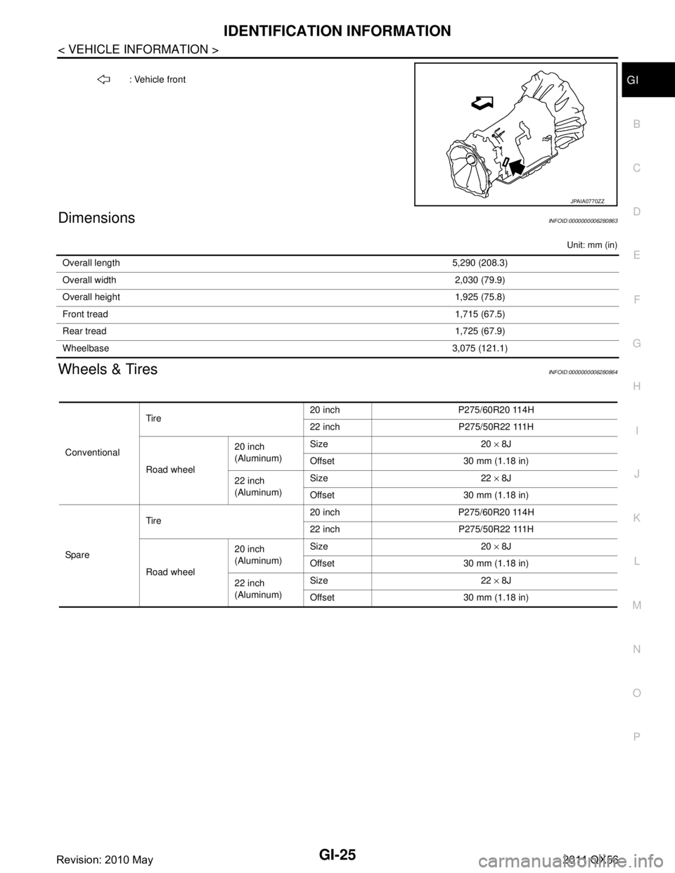
DimensionsINFOID:0000000006280863
Unit: mm (in)
Wheels & TiresINFOID:0000000006280864
: Vehicle front
JPAIA0770ZZ
Overall length 5,290 (208.3)
Overall width 2,030 (79.9)
Overall height 1,925 (75.8)
Front tread 1,715 (67.5)
Rear tread 1,725 (67.9)
Wheelbase 3,075 (121.1)
ConventionalTire
20 inch P275/60R20 114H
22 inch P275/50R22 111H
Road wheel 20 inch
(Aluminum)
Size 20
× 8J
Offset 30 mm (1.18 in)
22 inch
(Aluminum) Size 22
× 8J
Offset 30 mm (1.18 in)
Spare Tire
20 inch P275/60R20 114H
22 inch P275/50R22 111H
Road wheel 20 inch
(Aluminum)
Size 20
× 8J
Offset 30 mm (1.18 in)
22 inch
(Aluminum) Size 22
× 8J
Offset 30 mm (1.18 in)
Revision: 2010 May2011 QX56
Page 4989 of 5598

ST-2
STEERING WHEEL ...........................................33
Exploded View ..................................................... ...33
Removal and Installation ........................................33
STEERING COLUMN ........................................34
Exploded View ..................................................... ...34
Removal and Installation ........................................34
Inspection ...............................................................35
STEERING SHAFT ............................................37
Exploded View ..................................................... ...37
Removal and Installation ........................................37
Inspection ...............................................................39
STEERING GEAR AND LINKAGE ....................41
Exploded View ..................................................... ...41
Removal and Installation ........................................42
Disassembly and Assembly ....................................43
Inspection ...............................................................46
POWER STEERING OIL PUMP ........................48
Exploded View ..................................................... ...48
Removal and Installation ........................................49
Disassembly and Assembly ....................................50
Inspection ...............................................................52
HYDRAULIC LINE .......................................... ...54
Exploded View ..................................................... ...54
HEATED STEERING WHEEL SWITCH ............56
Exploded View ..................................................... ...56
Removal and Installation .........................................56
SERVICE DATA AND SPECIFICATIONS
(SDS) .......... ................................................
57
SERVICE DATA AND SPECIFICATIONS
(SDS) .............................................................. ...
57
General Specifications ......................................... ...57
Steering Wheel Axial End Play and Play ................57
Steering Wheel Turning Force ................................57
Steering Angle ........................................................57
Steering Column Length .........................................57
Steering Column Mounting Dimensions ..................57
Steering Column Operating Range .........................57
Steering Shaft Sliding Range ..................................58
Rack Sliding Force ..................................................58
Rack Stroke ............................................................58
Socket Swing Force and Rotating Torque ..............58
Socket Axial End Play .............................................58
Inner Socket Length ................................................58
Relief Oil Pressure ..................................................58
Revision: 2010 May2011 QX56
Page 5044 of 5598

SERVICE DATA AND SPECIFICATIONS (SDS)
ST-57
< SERVICE DATA AND SPECIFICATIONS (SDS)
C
D E
F
H I
J
K L
M A
B
ST
N
O P
SERVICE DATA AND SPECIFICATIONS (SDS)
SERVICE DATA AND SPECIFICATIONS (SDS)
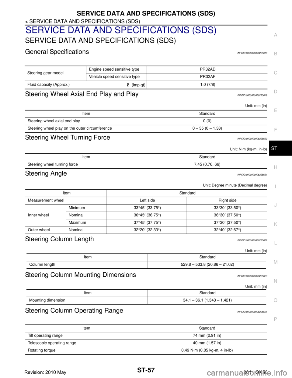
General SpecificationsINFOID:0000000006225618
Steering Wheel Axial End Play and PlayINFOID:0000000006225619
Unit: mm (in)
Steering Wheel Turning ForceINFOID:0000000006225620
Unit: N·m (kg-m, in-lb)
Steering AngleINFOID:0000000006225621
Unit: Degree minute (Decimal degree)
Steering Column LengthINFOID:0000000006225622
Unit: mm (in)
Steering Column Mounting DimensionsINFOID:0000000006225623
Unit: mm (in)
Steering Column Operating RangeINFOID:0000000006225624
Steering gear model Engine speed sensitive type PR32AD
Vehicle speed sensitive type PR32AF
Fluid capacity (Approx.) (lmp qt)1.0 (7/8)
Item Standard
Steering wheel axial end play 0 (0)
Steering wheel play on the outer circumference 0 – 35 (0 – 1.38)
Item Standard
Steering wheel turning force 7.45 (0.76, 66)
Item Standard
Measurement wheel Left side Right side
Inner wheel Minimum 33
°45 ′ (33.75 °)33 °30 ′ (33.50 °)
Nominal 36 °45 ′ (36.75 °)36 °30 ′ (37.50 °)
Maximum 37 °45 ′ (37.75 °)37 °30 ′ (37.50 °)
Outer wheel Nominal 32 °20 ′ (32.33 °)32 °40 ′ (32.67 °)
Item Standard
Column length 529.8 – 533.8 (20.86 – 21.02)
Item Standard
Mounting dimension 34.1 – 36.1 (1.343 – 1.421)
Item Standard
Tilt operating range 74 mm (2.91 in)
Telescopic operating range 40 mm (1.57 in)
Rotating torque 0.49 N· m (0.05 kg-m, 4 in-lb)
Revision: 2010 May2011 QX56
Page 5346 of 5598
![INFINITI QX56 2011 Factory Service Manual
TM-258
< UNIT DISASSEMBLY AND ASSEMBLY >[7AT: RE7R01B]
TRANSMISSION ASSEMBLY
a. Measure dimensions “K” and “L”, and calculate dimension “J”.
i. Measure dimension “K” between
the conv INFINITI QX56 2011 Factory Service Manual
TM-258
< UNIT DISASSEMBLY AND ASSEMBLY >[7AT: RE7R01B]
TRANSMISSION ASSEMBLY
a. Measure dimensions “K” and “L”, and calculate dimension “J”.
i. Measure dimension “K” between
the conv](/manual-img/42/57033/w960_57033-5345.png)
TM-258
< UNIT DISASSEMBLY AND ASSEMBLY >[7AT: RE7R01B]
TRANSMISSION ASSEMBLY
a. Measure dimensions “K” and “L”, and calculate dimension “J”.
i. Measure dimension “K” between
the converter housing fitting
surface of transmission case and the needle bearing mating sur-
face of under drive sun gear.
CAUTION:
Never change the straight edge installation position before
the completion of “L” measurement.
ii. Measure dimension “L” between the converter housing fitting surface of transmission case and the oil pump fitting surface of
transmission case.
iii. Measure dimension “K” and “L” in at least three places, and take the average.
iv. Calculate dimension “J”.
b. Measure dimensions “M
1” and “M2”, and calculate dimension
“M”.
1 : Transmission case
2 : Under drive sun gear
A : Straightedge
“J” : Distance between the oil pump fitting surface
of transmission case and the needle bearing
mating surface of under drive sun gear.
J = K – L
JSDIA1697ZZ
JSDIA1698ZZ
J = K – L
JSDIA1699ZZ
1 : Bearing race
2 : Needle bearing
3 : Oil pump assembly
A : Straightedge
“M” : Distance between the transmission case fit- ting surface of oil pump and the needle bearing
on oil pump.
M = M
1– M2
JSDIA1700ZZ
Revision: 2010 May2011 QX56
Page 5348 of 5598
![INFINITI QX56 2011 Factory Service Manual
TM-260
< UNIT DISASSEMBLY AND ASSEMBLY >[7AT: RE7R01B]
TRANSMISSION ASSEMBLY
49. Adjustment of front brake clearance “C”.
Measure clearance between front brake piston (1) and frontbrake retaini INFINITI QX56 2011 Factory Service Manual
TM-260
< UNIT DISASSEMBLY AND ASSEMBLY >[7AT: RE7R01B]
TRANSMISSION ASSEMBLY
49. Adjustment of front brake clearance “C”.
Measure clearance between front brake piston (1) and frontbrake retaini](/manual-img/42/57033/w960_57033-5347.png)
TM-260
< UNIT DISASSEMBLY AND ASSEMBLY >[7AT: RE7R01B]
TRANSMISSION ASSEMBLY
49. Adjustment of front brake clearance “C”.
Measure clearance between front brake piston (1) and frontbrake retaining plate (2).
Select proper thickness of front brake retaining plat so that
clearance is within specifications.
a. Measure dimensions “O” and “P”, and calculate dimension “N”.
i. Measure dimension “O” between the converter housing fitting surface of transmission case and the front brake retaining plate.
CAUTION:
Never change the straight edge installation position before
the completion of “P” measurement.
ii. Measure dimension “P” between the converter housing fitting
surface of transmission case and the oil pump fitting surface of
transmission case.
iii. Measure dimension “O” and “P” in at least three places, and take the average.
iv. Calculate dimension “N”.
JSDIA1704ZZ
1 : Transmission case
2 : Front brake retaining plate
A : Straightedge
“N” : Distance between the oil pump fitting surface of transmission case and the front brake retain-
ing plate.
N = O – P
JSDIA1705ZZ
1 : Transmission case
2 : Front brake retaining plate
A : Straightedge
JSDIA1706ZZ
1 : Transmission case
A : Straightedge
N = O – PJSDIA1707ZZ
Revision: 2010 May2011 QX56
Page 5349 of 5598
![INFINITI QX56 2011 Factory Service Manual
TRANSMISSION ASSEMBLYTM-261
< UNIT DISASSEMBLY AND ASSEMBLY > [7AT: RE7R01B]
C
EF
G H
I
J
K L
M A
B
TM
N
O P
b. Measure dimensions “Q1” and “Q2”, and calculate dimension
“Q”.
i. Measure d INFINITI QX56 2011 Factory Service Manual
TRANSMISSION ASSEMBLYTM-261
< UNIT DISASSEMBLY AND ASSEMBLY > [7AT: RE7R01B]
C
EF
G H
I
J
K L
M A
B
TM
N
O P
b. Measure dimensions “Q1” and “Q2”, and calculate dimension
“Q”.
i. Measure d](/manual-img/42/57033/w960_57033-5348.png)
TRANSMISSION ASSEMBLYTM-261
< UNIT DISASSEMBLY AND ASSEMBLY > [7AT: RE7R01B]
C
EF
G H
I
J
K L
M A
B
TM
N
O P
b. Measure dimensions “Q1” and “Q2”, and calculate dimension
“Q”.
i. Measure dimension “Q
1” between the transmission case fitting
surface of oil pump and the st raightedge on front brake piston.
CAUTION:
Measure dimension “M
2” in at least three places, and take
the average.
ii. Measure dimension “Q
2” of the straightedge.
iii. Calculate dimension “Q”.
c. Adjust front brake clearance “C”.
Select proper thickness of retaining plate so that front brakeclearance is within specifications.
1 : Front brake piston
2 : Oil pump assembly
A : Straightedge
“Q” : Distance between the transmission case fit-
ting surface of oil pump and the front brake pis-
ton.
Q = Q
1– Q2JSDIA1708ZZ
1 : Front brake piston
2 : Oil pump assembly
A : Straightedge
JSDIA1709ZZ
1 : Front brake piston
2 : Oil pump assembly
A : Straightedge
Q = Q1– Q2
JSDIA1711ZZ
1 : Front brake piston
2 : Front brake retaining plate
C = N – Q
Front brake clearance “C” : Refer to TM-298, "
Front
Brake Clearance".
Retaining plate : Refer to TM-298, "
Front Brake Clearance".
JSDIA1704ZZ
Revision: 2010 May2011 QX56