2011 INFINITI QX56 parking brake
[x] Cancel search: parking brakePage 5420 of 5598
![INFINITI QX56 2011 Factory Service Manual
WCS-16
< SYSTEM DESCRIPTION >
DIAGNOSIS SYSTEM (COMBINATION METER)
LCD
[B&P N, B&P I, ID NG, ROTAT, SFT
P, INSRT, BATT, NO KY, OUTKY, LK
WN]Displays status of Intelligent Key system warning judged INFINITI QX56 2011 Factory Service Manual
WCS-16
< SYSTEM DESCRIPTION >
DIAGNOSIS SYSTEM (COMBINATION METER)
LCD
[B&P N, B&P I, ID NG, ROTAT, SFT
P, INSRT, BATT, NO KY, OUTKY, LK
WN]Displays status of Intelligent Key system warning judged](/manual-img/42/57033/w960_57033-5419.png)
WCS-16
< SYSTEM DESCRIPTION >
DIAGNOSIS SYSTEM (COMBINATION METER)
LCD
[B&P N, B&P I, ID NG, ROTAT, SFT
P, INSRT, BATT, NO KY, OUTKY, LK
WN]Displays status of Intelligent Key system warning judged from meter display signal
received from BCM with CAN communication line.
ACC TARGET
[On/Off] Status of vehicle ahead detection indicator judged from meter display signal re-
ceived from ADAS control unit with CAN communication line.
ACC DISTANCE
[Off, Short, Middle, Long] Status of set distance indicator judged from meter display signal received from
ADAS control unit with
CAN communication line.
ACC OWN VHL
[On/Off] Status of own vehicle indicator judged from meter display signal received from
ADAS control unit with
CAN communication line.
ACC SET SPEED
[Off, km/h] Status of set vehicle speed indicator judged from meter display signal received
from ADAS control unit with CAN communication line.
ACC UNIT
[On/Off] Status of display unit judged from meter display signal received from ADAS con-
trol unit with CAN communication line.
SHIFT IND
[P, R, N, D, M1, M2, M3, M4, M5, M6,
M7] Status of shift position indicator judged from shift position signal and manual mode
indicator signal received from TCM with CAN communication line.
4WD IND
[AUTO, LOCK, 2W, 4Lo, HL1, HL2,
MALF] Status of 4WD indicator judged from 4WD indicator signal received from 4WD
control unit with CAN communication line.
BSW IND
[Off] This item is displayed, but cannot be monitored.
BSW W/L
[On/Off] Status of BSW warning lamp (orange) judged from BSW warning lamp signal re-
ceived from ADAS control unit with CAN communication line.
AT S MODE SW
[On/Off] Status of snow mode switch.
M RANGE SW
[On/Off] Status of manual mode switch.
NM RANGE SW
[On/Off] Status of non-manual mode switch.
AT SFT UP SW
[On/Off] Status of manual mode shift up switch.
AT SFT DWN SW
[On/Off] Status of manual mode shift down switch.
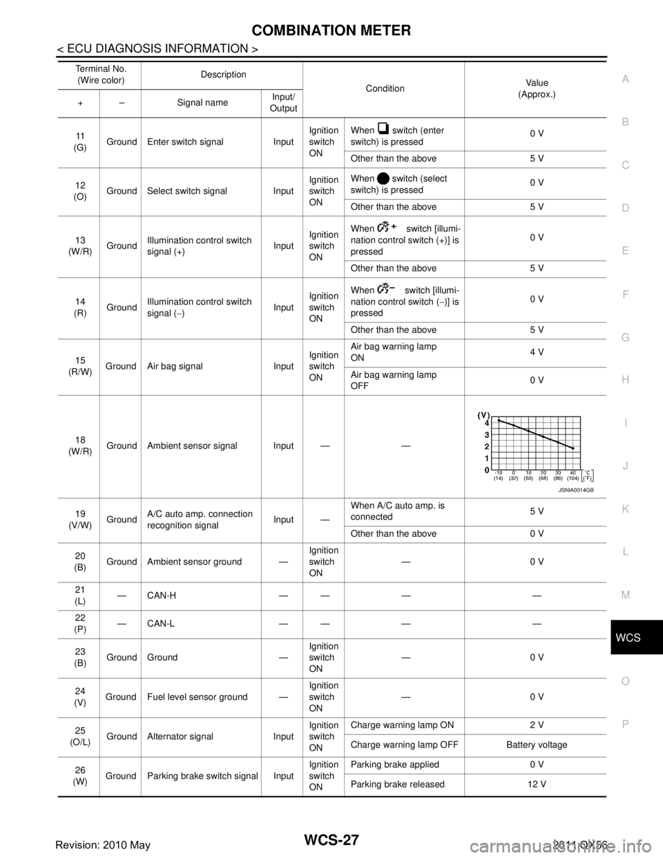
PKB SW
[On/Off] Status of parking brake switch.
BUCKLE SW
[On/Off] Status of seat belt buckle switch (driver side).
BRAKE OIL SW
[On/Off] Status of brake fluid level switch.
A/C AMP CONN
[Off] This item is displayed, but cannot be monitored.
ENTER SW
[On/Off] Status of (ENTER) switch.
SELECT SW
[On/Off] Status of (SELECT) switch.
DISTANCE
[km] Value of distance to empty calculated by combination meter.
OUTSIDE TEMP
[ ° C or °F] Ambient temperature value converted from ambient sensor signal received from
ambient sensor.
NOTE:
This may not match with the temperature value indicated on the information dis-
play. (Because the information display value is a corrected value from the ambient
sensor input value.)
Display item [Unit]
MAIN
SIGNALS Description
Revision: 2010 May2011 QX56
Page 5421 of 5598

WCS
DIAGNOSIS SYSTEM (COMBINATION METER)
WCS-17
< SYSTEM DESCRIPTION >
C
D E
F
G H
I
J
K L
M B A
O P
*: DDS (hill descent control) NOTE:
Some items are not available according to vehicle specification.
SPECIAL FUNCTION
Special menu
W/L ON HISTORY
Stores histories when warning/indicator lamp is turned on.
“W/L ON HISTORY” indicates the “TIME” when the warning/ indicator lamp is turned on.
The “TIME” above is:
- 0: The condition that the warning/indicator lamp has been turned on 1 or more times after starting the engine and waiting for 30 seconds.
- 1 - 39: The number of times the engine was restarted after the 0 condition.
- NO W/L ON HISTORY: Stores NO (0) turning on history of warning/indicator lamp.
NOTE:
W/L ON HISTORY is not stored for approximately 30 seconds after the engine starts.
Brake warning lamp does not store any history when the parking brake is applied or the brake fluid level gets
low.
Display Item
FUEL LOW SIG
[On/Off] Status of fuel level low warning signal to output to AV control unit via CAN com-
munication.
TOW MODE IND
[On/Off] Status of TOW mode indicator lamp judged from TOW mode indicator lamp signal
received from TCM with CAN communication line.
BUZZER
[On/Off] XBuzzer status (in the combination meter) is detected from the buzzer output signal
received from each unit via CAN communication and the warning output condition
of the combination meter.
Display item [Unit]
MAIN
SIGNALS Description
Display item Description
W/L ON HISTORY Lighting history of warning lamp and indicator lamp can be checked.
Display item Description
ABS W/L Lighting history of ABS warning lamp.
VDC/TCS IND Lighting history of VDC OFF indicator lamp.
SLIP IND Lighting history of VDC warning lamp.
BRAKE W/L Lighting history of brake warning lamp.
DOOR W/L Lighting history of door open warning.
TRUNK/GLAS-H This item is displayed, but cannot be monitored.
OIL W/L Lighting history of oil pressure warning lamp.
C-ENG W/L Lighting history of malfunction indicator lamp.
C-ENG2 W/L This item is displayed, but cannot be monitored.
CRUISE IND Lighting history of CRUISE indicator lamp.
SET IND Lighting history of SET indicator lamp.
CRUISE W/L Lighting histor y of CRUISE warning lamp.
BA W/L Lighting history of IBA OFF indicator lamp.
O/D OFF IND This item is displayed, but cannot be monitored.
ATC/T-AMT W/L Lighting history of A/T CHECK warning lamp.
ATF TEMP W/L This item is displayed, but cannot be monitored.
CVT IND This item is displayed, but cannot be monitored.
SPORT IND This item is displayed, but cannot be monitored.
Revision: 2010 May2011 QX56
Page 5429 of 5598

WCS
COMBINATION METERWCS-25
< ECU DIAGNOSIS INFORMATION >
C
DE
F
G H
I
J
K L
M B A
O P
SHIFT IND Ignition switch
ONDuring the indication of “P” by shift position
indicator
P
During the indication of “R” by shift position
indicator R
During the indication of “N” by shift position
indicator N
During the indication of “D” by shift position
indicator D
During the indication of “M1” by shift posi-
tion indicator M1
During the indication of “M2” by shift posi-
tion indicator M2
During the indication of “M3” by shift posi-
tion indicator M3
During the indication of “M4” by shift posi-
tion indicator M4
During the indication of “M5” by shift posi-
tion indicator M5
During the indication of “M6” by shift posi-
tion indicator M6
During the indication of “M7” by shift posi-
tion indicator M7
4WD IND Ignition switch
ON4WD shift switch in AUTO position AUTO
4WD shift switch in 4H position LOCK
4WD shift switch in 4L position LOCK/4Lo
BSW IND Ignition switch
ONNOTE:
This item is displayed, but cannot be moni-
tored.
Off
BSW W/L Ignition switch
ONBSW warning lamp ON On
BSW warning lamp OFF Off
AT S MODE SW Ignition switch
ONSnow mode switch ON On
Snow mode switch OFF Off
M RANGE SW Ignition switch
ONSelector lever in manual mode position On
Other than the above Off
NM RANGE SW Ignition switch
ONSelector lever in manual mode position Off
Other than the above On
AT SFT UP SW Ignition switch
ONSelector lever in + position On
Other than the above Off
AT SFT DWN SW Ignition switch
ONSelector lever in – position On
Other than the above Off
PKB SW Ignition switch
ONParking brake switch ON On
Parking brake switch OFF Off
BUCKLE SW Ignition switch
ONDriver seat belt not fastened On
Driver seat belt fastened Off
BRAKE OIL SW Ignition switch
ONBrake fluid level switch ON On
Brake fluid level switch OFF Off
A/C AMP CONN Ignition switch
ONNOTE:
This item is displayed, but cannot be moni-
tored.
Off
Monitor Item Condition Value/Status
Revision: 2010 May2011 QX56
Page 5431 of 5598

WCS
COMBINATION METERWCS-27
< ECU DIAGNOSIS INFORMATION >
C
DE
F
G H
I
J
K L
M B A
O P
11
(G) Ground Enter switch signal Input Ignition
switch
ONWhen switch (enter
switch) is pressed
0 V
Other than the above 5 V
12
(O) Ground Select switch signal Input Ignition
switch
ONWhen switch (select
switch) is pressed
0 V
Other than the above 5 V
13
(W/R) Ground
Illumination control switch
signal (+) InputIgnition
switch
ON When switch [illumi-
nation control switch (+)] is
pressed
0 V
Other than the above 5 V
14
(R) Ground Illumination control switch
signal (
−) InputIgnition
switch
ON When switch [illumi-
nation control switch (
−)] is
pressed 0 V
Other than the above 5 V
15
(R/W) Ground Air bag signal Input Ignition
switch
ONAir bag warning lamp
ON
4 V
Air bag warning lamp
OFF 0 V
18
(W/R) Ground Ambient sensor signal Input — —
19
(V/W) Ground A/C auto amp. connection
recognition signal Input —When A/C auto amp. is
connected
5 V
Other than the above 0 V
20
(B) Ground Ambient sensor ground — Ignition
switch
ON—0 V
21
(L) —CAN-H — — — —
22
(P) —CAN-L — — — —
23
(B) Ground Ground — Ignition
switch
ON
—0 V
24
(V) Ground Fuel level sensor ground — Ignition
switch
ON—0 V
25
(O/L) Ground Alternator signal Input Ignition
switch
ONCharge warning lamp ON 2 V
Charge warning lamp OFF Battery voltage
26
(W) Ground Parking brake switch signal Input Ignition
switch
ONParking brake applied 0 V
Parking brake released 12 V
Te r m i n a l N o .
(Wire color) Description
ConditionVa l u e
(Approx.)
+ – Signal name Input/
Output
JSNIA0014GB
Revision: 2010 May2011 QX56
Page 5447 of 5598

WCS
PARKING BRAKE SWITCH SIGNAL CIRCUITWCS-43
< DTC/CIRCUIT DIAGNOSIS >
C
DE
F
G H
I
J
K L
M B A
O P
PARKING BRAKE SWITCH SIGNAL CIRCUIT
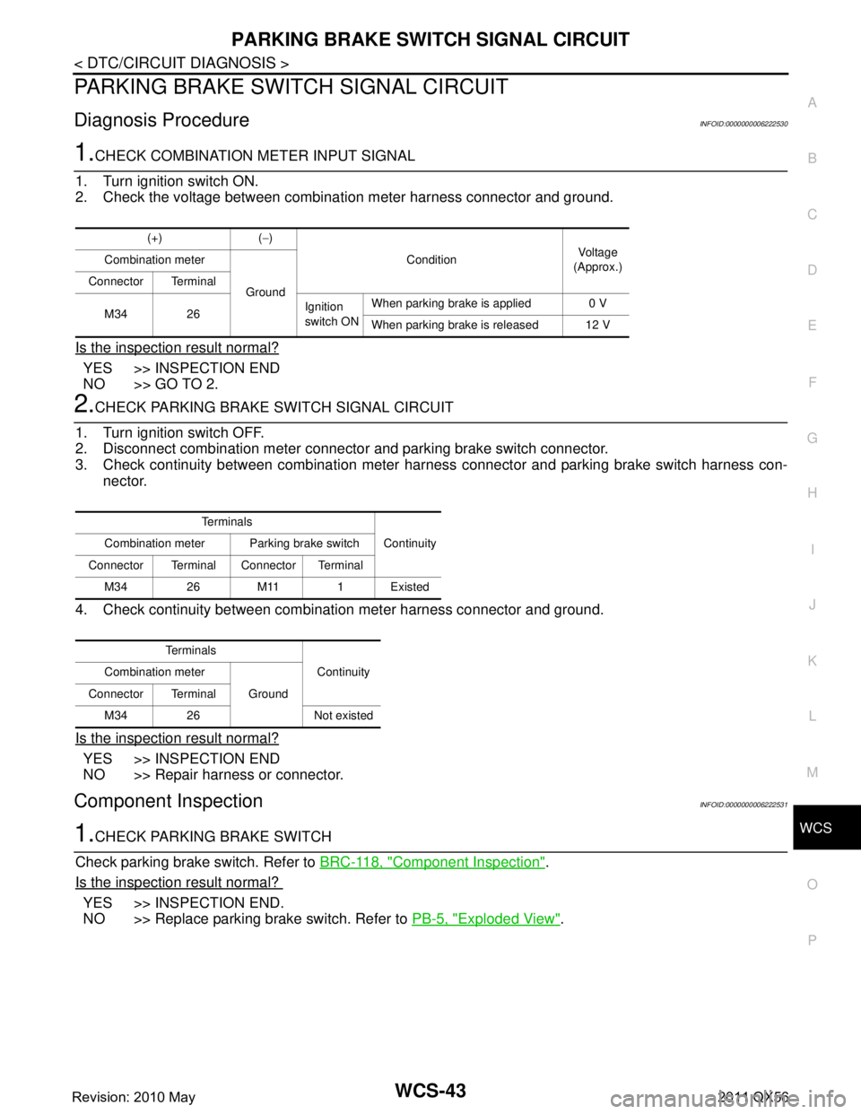
Diagnosis ProcedureINFOID:0000000006222530
1.CHECK COMBINATION METER INPUT SIGNAL
1. Turn ignition switch ON.
2. Check the voltage between combination meter harness connector and ground.
Is the inspection result normal?
YES >> INSPECTION END
NO >> GO TO 2.
2.CHECK PARKING BRAKE SWITCH SIGNAL CIRCUIT
1. Turn ignition switch OFF.
2. Disconnect combination meter connecto r and parking brake switch connector.
3. Check continuity between combination meter har ness connector and parking brake switch harness con-
nector.
4. Check continuity between combination meter harness connector and ground.
Is the inspection result normal?
YES >> INSPECTION END
NO >> Repair harness or connector.
Component InspectionINFOID:0000000006222531
1.CHECK PARKING BRAKE SWITCH
Check parking brake switch. Refer to BRC-118, "
Component Inspection".
Is the inspection result normal?
YES >> INSPECTION END.
NO >> Replace parking brake switch. Refer to PB-5, "
Exploded View".
(+) (−)
Condition Vo l ta g e
(Approx.)
Combination meter
Ground
Connector Terminal
M34 26 Ignition
switch ONWhen parking brake is applied 0 V
When parking brake is released 12 V
Te r m i n a l s
Continuity
Combination meter Parking brake switch
Connector Terminal Connector Terminal M34 26 M11 1 Existed
Te r m i n a l s Continuity
Combination meter
Ground
Connector Terminal
M34 26 Not existed
Revision: 2010 May2011 QX56
Page 5450 of 5598

WCS-46
< SYMPTOM DIAGNOSIS >
THE PARKING BRAKE RELEASE WARNING CONTINUES SOUNDING, OR
DOES NOT SOUND
THE PARKING BRAKE RELEASE WARNING CONTINUES SOUNDING, OR
DOES NOT SOUND
DescriptionINFOID:0000000006222534
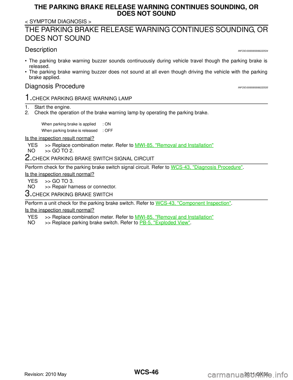
The parking brake warning buzzer sounds continuously during vehicle travel though the parking brake is
released.
The parking brake warning buzzer does not sound at a ll even though driving the vehicle with the parking
brake applied.
Diagnosis ProcedureINFOID:0000000006222535
1.CHECK PARKING BRAKE WARNING LAMP
1. Start the engine.
2. Check the operation of the brake warni ng lamp by operating the parking brake.
Is the inspection result normal?
YES >> Replace combination meter. Refer to MWI-85, "Removal and Installation"
NO >> GO TO 2.
2.CHECK PARKING BRAKE SWITCH SIGNAL CIRCUIT
Perform check for the parking brake switch signal circuit. Refer to WCS-43, "
Diagnosis Procedure".
Is the inspection result normal?
YES >> GO TO 3.
NO >> Repair harness or connector.
3.CHECK PARKING BRAKE SWITCH
Perform a unit check for the parking brake switch. Refer to WCS-43, "
Component Inspection".
Is the inspection result normal?
YES >> Replace combination meter. Refer to MWI-85, "Removal and Installation"
NO >> Replace parking brake switch. Refer to PB-5, "Exploded View".
When parking brake is applied : ON
When parking brake is released : OFF
Revision: 2010 May2011 QX56
Page 5537 of 5598

WW-18
< SYSTEM DESCRIPTION >
DIAGNOSIS SYSTEM (IPDM E/R)
DIAGNOSIS SYSTEM (IPDM E/R)
Diagnosis DescriptionINFOID:0000000006349814
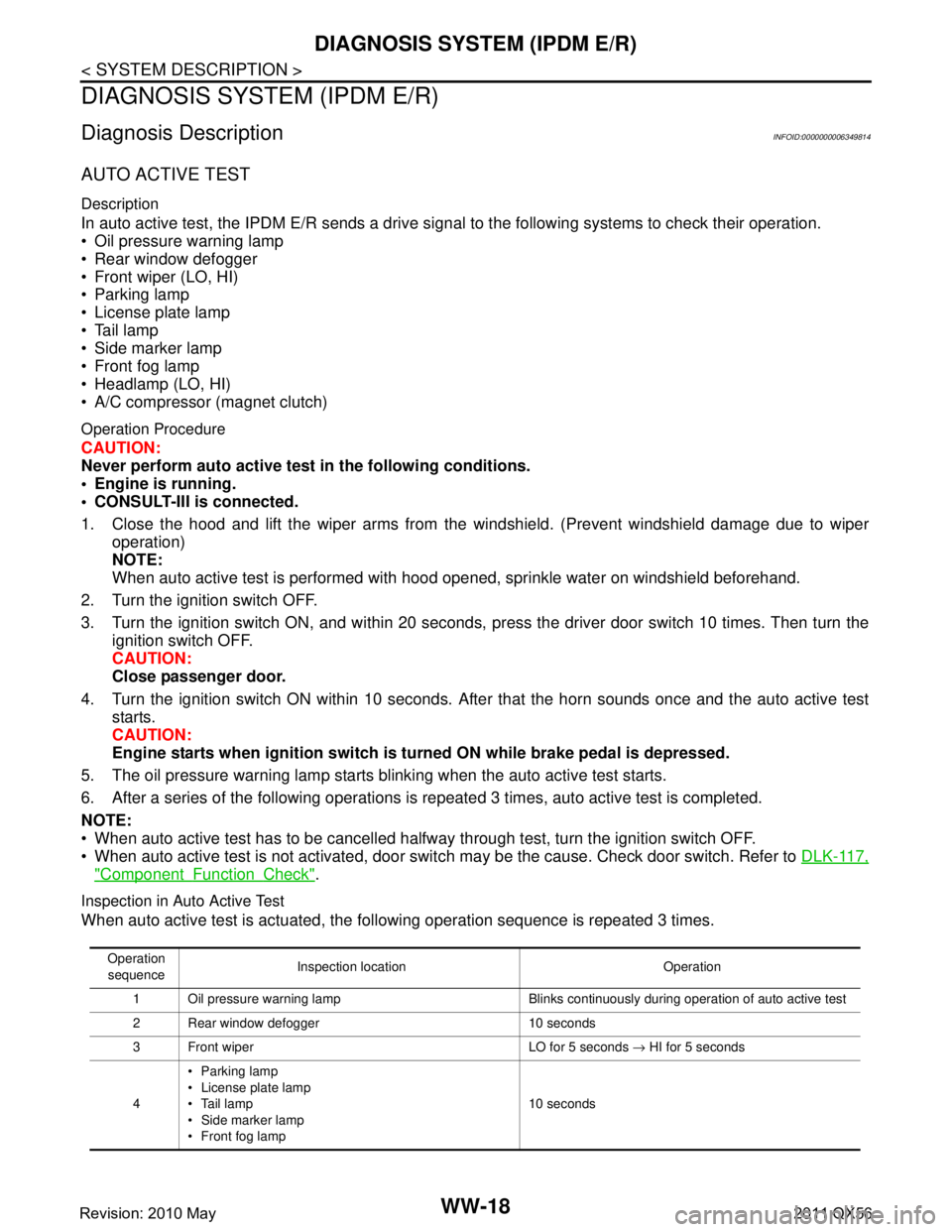
AUTO ACTIVE TEST
Description
In auto active test, the IPDM E/R sends a drive signal to the following systems to check their operation.
Oil pressure warning lamp
Rear window defogger
Front wiper (LO, HI)
Parking lamp
License plate lamp
Tail lamp
Side marker lamp
Front fog lamp
Headlamp (LO, HI)
A/C compressor (magnet clutch)
Operation Procedure
CAUTION:
Never perform auto active test in the following conditions.
Engine is running.
CONSULT-III is connected.
1. Close the hood and lift the wiper arms from the windshield. (Prevent windshield damage due to wiper
operation)
NOTE:
When auto active test is performed with hood opened, sprinkle water on windshield beforehand.
2. Turn the ignition switch OFF.
3. Turn the ignition switch ON, and within 20 seconds, pr ess the driver door switch 10 times. Then turn the
ignition switch OFF.
CAUTION:
Close passenger door.
4. Turn the ignition switch ON within 10 seconds. Af ter that the horn sounds once and the auto active test
starts.
CAUTION:
Engine starts when igniti on switch is turned ON while brake pedal is depressed.
5. The oil pressure warning lamp starts blinking when the auto active test starts.
6. After a series of the following operations is repeated 3 times, auto active test is completed.
NOTE:
When auto active test has to be cancelled halfway through test, turn the ignition switch OFF.
When auto active test is not activated, door swit ch may be the cause. Check door switch. Refer to DLK-117,
"ComponentFunctionCheck".
Inspection in Auto Active Test
When auto active test is actuated, the following operation sequence is repeated 3 times.
Operation
sequence Inspection location Operation
1 Oil pressure warning lamp Blinks continuously during operation of auto active test
2 Rear window defogger 10 seconds
3 Front wiper LO for 5 seconds → HI for 5 seconds
4 Parking lamp
License plate lamp
Tail lamp
Side marker lamp
Front fog lamp 10 seconds
Revision: 2010 May2011 QX56