2011 INFINITI QX56 parking brake
[x] Cancel search: parking brakePage 4274 of 5598
REAR SUSPENSION MEMBERRSU-19
< UNIT REMOVAL AND INSTALLATION >
C
DF
G H
I
J
K L
M A
B
RSU
N
O P
16. Remove final drive. Refer to DLN-201, "Removal and Installation".
17. Remove rear tube assembly A and rear tube assembly B. (With HBMC) Refer to SCS-44, "
REAR TUBE
ASSEMBLY : Removal and Installation".
18. Set suitable jack under rear suspension member.
19. Slowly lower jack, then remove rear suspension member, suspension arm, front lower link, wheel hub and housing from vehicle as a unit.
20. Remove mounting bolts and nuts, then remove suspension arm, front lower link, wheel hub and housing from rear suspension member.
21. Perform inspection after removal. Refer to RSU-19, "
Inspection and Adjustment".
INSTALLATION
Note the following, and install in the reverse order of the removal.
Perform the final tightening of each of parts under unladen conditions, which were removed when removing
rear suspension assembly.
Perform inspection after installation. Refer to RSU-19, "
Inspection and Adjustment".
Perform adjustment after installation. (With HBMC) Refer to RSU-19, "
Inspection and Adjustment".
Inspection and AdjustmentINFOID:0000000006225678
INSPECTION AFTER REMOVAL
Check rear suspension member for deformation, cracks, or any other damage. Replace if necessary.
INSPECTION AFTER INSTALLATION
1. Adjust parking brake operation (stroke). Refer to PB-3, "Inspection and Adjustment".
2. Check wheel alignment. Refer to RSU-6, "
Inspection".
3. Adjust neutral position of steering angle sensor. Refer to BRC-64, "
Work Procedure".
4. Adjust levelizer adjustment of height sensor. Refer to EXL-61, "
LEVELIZER ADJUSTMENT : Special
Repair Requirement".
5. Check standard vehicle height setting of vehicle height sensor. Refer to SCS-67, "
Work Procedure".
6. Check wheel sensor harness for proper connection. Refer to BRC-135, "
REAR WHEEL SENSOR :
Exploded View"
ADJUSTMENT AFTER INSTALLATION (WITH HBMC)
Bleed air from the HBMC. Refer to SCS-18, "Work Procedure".
Revision: 2010 May2011 QX56
Page 4280 of 5598
FRONT SEAT BELTSB-5
< REMOVAL AND INSTALLATION >
C
DE
F
G
I
J
K L
M A
B
SB
N
O P
SEAT BELT RETRACTOR ON-VEHICLE CHECK
Emergency Locking Retractors (ELR) and Automatic Locking Retractors (ALR)
NOTE:
All seat belt retractors are Emergency Locking Retr actors (ELR) type. In an emergency (sudden stop) the
retractor will lock and prevent the webbing from extendi ng any further. All 3-point type seat belt retractors
except the driver seat belt also have an Automati c Locking Retractors (ALR) mode. The ALR mode (also
called child restraint mode) is used when installing child seats. The ALR mode is activated when the seat belt
is fully extended. When the webbing is then retracted part ially, the ALR mode automatically locks the seat belt
in a specific position so the webbi ng cannot be extended any further. To c ancel the ALR mode, allow the seat
belt to fully wind back into the retractor.
Check the seat belt retractors with the following test(s ) to determine if a retractor assembly is operating prop-
erly.
ELR Function Stationary Check
Grasp the shoulder webbing and pull forward quickly. The retractor should lock and prevent the belt from
extending further.
ALR Function Stationary Check
1. Pull out the entire length of seat bel t from retractor until a click is heard.
2. Retract the webbing partially. A clicking noise should be heard as the webbing retracts indicating that the
retractor is in the Automatic Locking Retractors (ALR) mode.
3. Grasp the seat belt and try to pull out the retractor. The webbing must lock and not extend any further. If it
does not operate normally, replace the retractor assembly.
4. Allow the entire length of the webbing to retract to cancel the automatic locking mode.
ELR Function Moving Check
WARNING:
Perform the following test in a safe, open area clear of other vehicles and obstructions (for example, a
large, empty parking lot). Road surface must be p aved and dry. Never perform the following test on
wet or gravel roads or on public streets and highways. This could result in an accident and serious
personal injury. The driver and passenger must be prepared to brace themselves in the event that the
retractor does not lock.
1. Fasten driver seat belt. Buckle a passenger into the seat for the belt that is to be tested.
2. Proceed to the designated safe area.
3. Drive the vehicle at approximately 16 km/h ( 10 MPH). Notify any passengers of a pending sudden stop
and the driver and passenger must be prepared to brac e themselves in the event that the retractor does
not lock. Apply brakes firmly and make a very hard stop.
During stopping, seat belts should lock and not be extended. If the seat belt retractor assembly does not lock,
perform the retractor off-vehicle check.
SEAT BELT RETRACTOR OFF-VEHICLE CHECK
1. Remove the front seat belt retractor. Refer to SB-6, "SEAT BELT RETRACTOR : Removal and Installa-
tion".
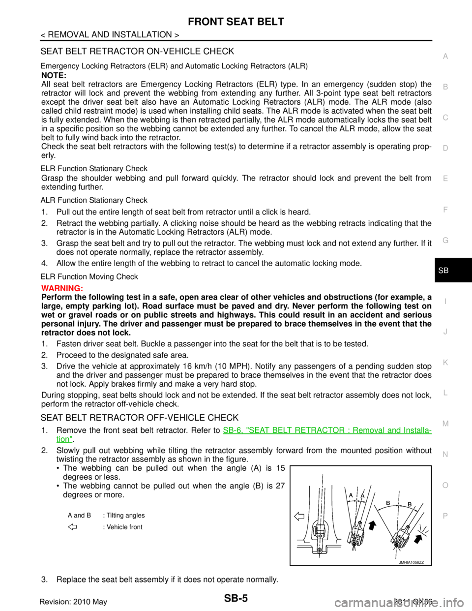
2. Slowly pull out webbing while tilting the retracto r assembly forward from the mounted position without
twisting the retractor assembly as shown in the figure.
The webbing can be pulled out when the angle (A) is 15
degrees or less.
The webbing cannot be pulled out when the angle (B) is 27
degrees or more.
3. Replace the seat belt assembly if it does not operate normally.
A and B : Tilting angles : Vehicle front
JMHIA1056ZZ
Revision: 2010 May2011 QX56
Page 4286 of 5598
SECOND SEAT BELTSB-11
< REMOVAL AND INSTALLATION >
C
DE
F
G
I
J
K L
M A
B
SB
N
O P
3. Grasp the seat belt and try to pull out the retractor. The webbing must lock and not extend any further. If it
does not operate normally, replace the retractor assembly.
4. Allow the entire length of the webbing to retract to cancel the automatic locking mode.
ELR Function Moving Check
WARNING:
Perform the following test in a safe, open area clear of other vehicles and obstructions (for example, a
large, empty parking lot). Road surface must be p aved and dry. Never perform the following test on
wet or gravel roads or on public streets and highways. This could result in an accident and serious
personal injury. The driver and passenger must be prepared to brace themselves in the event that the
retractor does not lock.
1. Fasten driver seat belt. Buckle a passenger into the seat for the belt that is to be tested.
2. Proceed to the designated safe area.
3. Drive the vehicle at approximately 16 km/h ( 10 MPH). Notify any passengers of a pending sudden stop
and the driver and passenger must be prepared to brac e themselves in the event that the retractor does
not lock. Apply brakes firmly and make a very hard stop.
During stopping, seat belts should lock and not be extended. If the seat belt retractor assembly does not lock,
perform the retractor off-vehicle check.
SEAT BELT RETRACTOR OFF-VEHICLE CHECK
1. Remove the second seat belt retractor. Refer to SB-13, "SEAT BELT RETRACTOR : Removal and Instal-
lation".
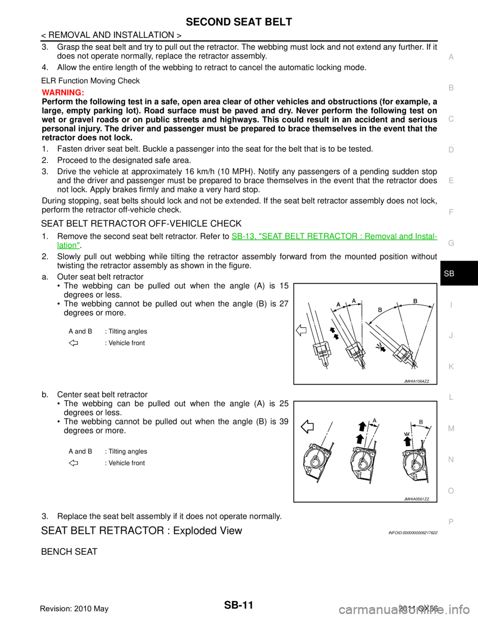
2. Slowly pull out webbing while tilting the retracto r assembly forward from the mounted position without
twisting the retractor assembly as shown in the figure.
a. Outer seat belt retractor The webbing can be pulled out when the angle (A) is 15degrees or less.
The webbing cannot be pulled out when the angle (B) is 27
degrees or more.
b. Center seat belt retractor The webbing can be pulled out when the angle (A) is 25
degrees or less.
The webbing cannot be pulled out when the angle (B) is 39
degrees or more.
3. Replace the seat belt assembly if it does not operate normally.
SEAT BELT RETRACTOR : Exploded ViewINFOID:0000000006217622
BENCH SEAT
A and B : Tilting angles : Vehicle front
JMHIA1064ZZ
A and B : Tilting angles
: Vehicle front
JMHIA0561ZZ
Revision: 2010 May2011 QX56
Page 4293 of 5598
SB-18
< REMOVAL AND INSTALLATION >
THIRD SEAT BELT
3. Grasp the seat belt and try to pull out the retractor. The webbing must lock and not extend any further. If it
does not operate normally, replace the retractor assembly.
4. Allow the entire length of the webbing to re tract to cancel the automatic locking mode.
ELR Function Moving Check
WARNING:
Perform the following test in a safe, open area clear of other vehicles and obstructions (for example, a
large, empty parking lot). Road surface must be p aved and dry. Never perform the following test on
wet or gravel roads or on public streets and highw ays. This could result in an accident and serious
personal injury. The driver and passenger must be prepared to brace themselves in the event that the
retractor does not lock.
1. Fasten driver seat belt. Buckle a passenger in to the seat for the belt that is to be tested.
2. Proceed to the designated safe area.
3. Drive the vehicle at approximately 16 km/h ( 10 MPH). Notify any passengers of a pending sudden stop
and the driver and passenger must be prepared to brace themselves in the event that the retractor does
not lock. Apply brakes firmly and make a very hard stop.
During stopping, seat belts should lock and not be extended. If the seat belt retractor assembly does not lock,
perform the retractor off-vehicle check.
SEAT BELT RETRACTOR OFF-VEHICLE CHECK
1. Remove the third seat belt retractor. Refer to SB-19, "SEAT BELT RETRACTOR : Removal and Installa-
tion".
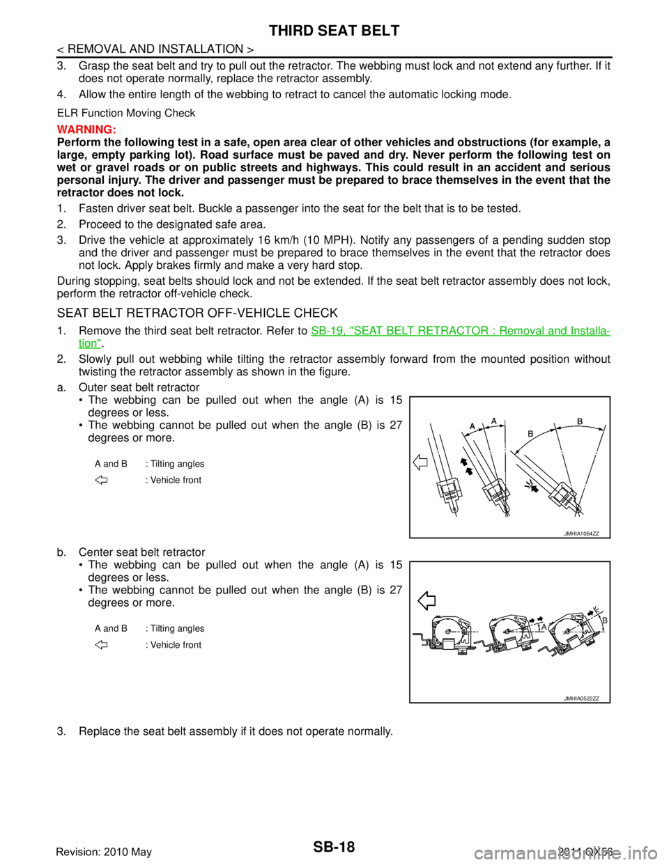
2. Slowly pull out webbing while tilting the retracto r assembly forward from the mounted position without
twisting the retractor assembly as shown in the figure.
a. Outer seat belt retractor The webbing can be pulled out when the angle (A) is 15degrees or less.
The webbing cannot be pulled out when the angle (B) is 27
degrees or more.
b. Center seat belt retractor The webbing can be pulled out when the angle (A) is 15
degrees or less.
The webbing cannot be pulled out when the angle (B) is 27
degrees or more.
3. Replace the seat belt assembly if it does not operate normally.
A and B : Tilting angles : Vehicle front
JMHIA1064ZZ
A and B : Tilting angles: Vehicle front
JMHIA0522ZZ
Revision: 2010 May2011 QX56
Page 5001 of 5598
ST-14
< BASIC INSPECTION >
STEERING WHEEL
STEERING WHEEL
InspectionINFOID:0000000006225584
NEUTRAL POSITION STEERING WHEEL
1. Check that steering gear assembly, steering column assembly and steering wheel are installed in the cor-
rect position.
2. Perform neutral position inspection after wheel alignment. Refer to FSU-7, "
Inspection".
3. Set vehicle to the straight-ahead position and c onfirm steering wheel is in the neutral position.
4. Loosen outer socket lock nut and turn inner socket to left and right equally to make fine adjustments if steering wheel is not in the neutral position.
STEERING WHEEL TURNING FORCE
1. Park vehicle on a level and dry surface, set parking brake.
2. Tires need to be inflated the specified pressure. Refer to WT-69, "
Tire Air Pressure".
3. Start the engine.
4. Bring power steering fluid up to adequate operating temperature.
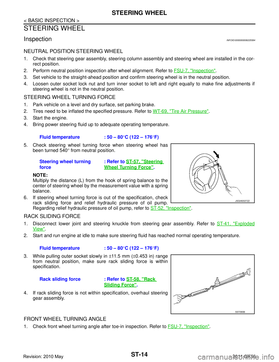
5. Check steering wheel turning force when steering wheel has been turned 540 ° from neutral position.
NOTE:
Multiply the distance (L) from the hook of spring balance to the
center of steering wheel by the measurement value with a spring
balance.
6. If steering wheel turning force is out of the specification, check
rack sliding force and relief hydraulic pressure of oil pump.
Regarding relief hydraulic pressure of oil pump, refer to ST-52, "
Inspection".
RACK SLIDING FORCE
1. Disconnect lower joint and steering knuckle from steering gear assembly. Refer to ST-41, "Exploded
View".
2. Start and run engine at idle to make sure steer ing fluid has reached normal operating temperature.
3. While pulling outer socket slowly in ±11.5 mm ( ±0.453 in) range
from neutral position, make sure rack sliding force is within
specification.
4. If rack sliding force is not within specification, overhaul steering gear assembly.
FRONT WHEEL TURNING ANGLE
1. Check front wheel turning angle after toe-in inspection. Refer to FSU-7, "Inspection".
Fluid temperature : 50 – 80
°C (122 – 176 °F)
Steering wheel turning
force : Refer to
ST-57, "
Steering
Wheel Turning Force".
JSGIA0027ZZ
Fluid temperature : 50 – 80 °C (122 – 176 °F)
Rack sliding force : Refer to ST-58, "
Rack
Sliding Force".
SST090B
Revision: 2010 May2011 QX56
Page 5092 of 5598

TM-4
Component Inspection (Shift Lock Solenoid) ........159
SELECTOR LEVER POSITION INDICATOR ..161
Component Function Check ................................ ..161
Diagnosis Procedure .............................................161
Component Inspection (Selector Lever Position
Indicator) ................................................................
163
SYMPTOM DIAGNOSIS ............................165
SYSTEM SYMPTOM ...................................... .165
Symptom Table ................................................... ..165
PERIODIC MAINTENANCE ..................... ..175
A/T FLUID ....................................................... .175
Inspection ............................................................ ..175
REMOVAL AND INSTALLATION ..............176
A/T SHIFT SELECTOR ................................... .176
Exploded View ..................................................... ..176
Removal and Installation .......................................176
Inspection and Adjustment ....................................177
CONTROL CABLE ..........................................178
Exploded View ..................................................... ..178
Removal and Installation .......................................178
Inspection and Adjustment ....................................179
SELECTOR LEVER POSITION INDICATOR ..180
Removal and Installation ..................................... ..180
TOW MODE SWITCH ......................................181
Removal and Installation ..................................... ..181
CONTROL VALVE & TCM ..............................182
Exploded View ..................................................... ..182
Removal and Installation .......................................182
Inspection and Adjustment ....................................186
PARKING COMPONENTS ..............................187
2WD ........................................................................ ..187
2WD : Exploded View ............................................187
2WD : Removal and Installation ............................187
2WD : Inspection ...................................................190
REAR OIL SEAL ..............................................192
2WD ........................................................................ ..192
2WD : Exploded View ............................................192
2WD : Removal and Installation ............................192
2WD : Inspection ...................................................193
4WD ........................................................................ ..193
4WD : Exploded View ............................................193
4WD : Removal and Installation ............................193
4WD : Inspection and Adjustment .........................194
OUTPUT SPEED SENSOR .............................195
2WD ........................................................................ ..195
2WD : Exploded View ...........................................195
2WD : Removal and Installation ............................195
2WD : Inspection and Adjustment .........................198
AIR BREATHER HOSE ....................................199
2WD ........................................................................ .199
2WD : Exploded View ...........................................199
2WD : Removal and Installation ............................199
4WD ........................................................................ .200
4WD : Exploded View ...........................................200
4WD : Removal and Installation ............................200
FLUID COOLER SYSTEM ...............................202
Exploded View ..................................................... .202
Removal and Installation .......................................202
Inspection and Adjustment ....................................204
UNIT REMOVAL AND INSTALLATION ...205
TRANSMISSION ASSEMBLY ..........................205
2WD ........................................................................ .205
2WD : Exploded View ...........................................205
2WD : Removal and Installation ............................205
2WD : Inspection and Adjustment .........................207
4WD ........................................................................ .207
4WD : Exploded View ...........................................208
4WD : Removal and Installation ............................208
4WD : Inspection and Adjustment .........................210
UNIT DISASSEMBLY AND ASSEMBLY ..211
TRANSMISSION ASSEMBLY ..........................211
Exploded View ..................................................... .211
Oil Channel ...........................................................222
Location of Needle Bearings and Bearing Races .222
Location of Snap Rings .........................................225
Disassembly ..........................................................226
Assembly ..............................................................243
Inspection ..............................................................267
OIL PUMP, 2346 BRAKE, FRONT BRAKE
PISTON .............................................................
270
Exploded View ..................................................... .270
Disassembly ..........................................................270
Assembly ..............................................................274
Inspection and Adjustment ....................................277
UNDER DRIVE CARRIER, FRONT BRAKE
HUB ..................................................................
279
Exploded View ..................................................... .279
Disassembly ..........................................................279
Assembly ..............................................................280
Inspection ..............................................................280
FRONT CARRIER, INPUT CLUTCH, REAR
INTERNAL GEAR .............................................
282
Exploded View ..................................................... .282
Disassembly ..........................................................283
Revision: 2010 May2011 QX56
Page 5095 of 5598
![INFINITI QX56 2011 Factory Service Manual
PRECAUTIONSTM-7
< PRECAUTION > [7AT: RE7R01B]
C
EF
G H
I
J
K L
M A
B
TM
N
O P
Disassembly should be done in a clean work area.
Use lint-free paper or towels for wiping parts clean. Common shop r INFINITI QX56 2011 Factory Service Manual
PRECAUTIONSTM-7
< PRECAUTION > [7AT: RE7R01B]
C
EF
G H
I
J
K L
M A
B
TM
N
O P
Disassembly should be done in a clean work area.
Use lint-free paper or towels for wiping parts clean. Common shop r](/manual-img/42/57033/w960_57033-5094.png)
PRECAUTIONSTM-7
< PRECAUTION > [7AT: RE7R01B]
C
EF
G H
I
J
K L
M A
B
TM
N
O P
Disassembly should be done in a clean work area.
Use lint-free paper or towels for wiping parts clean. Common shop rags can leave fibers that could interfere
with the operation of the transmission.
Place disassembled parts in order for easier and proper assembly.
All parts should be carefully cleaned with a general purpose, non-flammable solvent before inspection or
reassembly.
Gaskets, seals and O-rings should be repl aced any time the A/T is disassembled.
It is very important to perform func tional tests whenever they are indicated.
The valve body contains precision parts and requires extreme care when parts are removed and serviced.
Place disassembled valve body parts in order for easier and proper assembly. Care will also prevent springs
and small parts from becoming scattered or lost.
Properly installed valves, sleeves, plugs, etc. will slide along bores in valve body under their own weight.
Before assembly, apply a coat of recommended ATF to all parts. Apply petroleum jelly to protect O-rings and
seals, or hold bearings and washers in place during assembly. Never use grease.
Extreme care should be taken to avoid damage to O-rings, seals and gaskets when assembling.
When the A/T drain plug is removed, only some of the ATF is drained. Old ATF will remain in torque con- verter and ATF cooling system.
Always follow the procedures under “Changing” when changing ATF. Refer to TM-94, "
Changing".
Occasionally, the parking gear may be locked with the to rque insufficiently released, when stopping the vehi-
cle by shifting the selector lever from “D” or “R” to “P” position with the brake pedal depressed.
In this case, the shock with a thud caused by the abrupt release of torque may occur when shifting the selec-
tor lever from “P” posit ion to other positions.
However, this symptom is not a malfunction which results in the damage of parts.
Service Notice or PrecautionINFOID:0000000006274263
ATF COOLER SERVICE
If ATF contains frictional material (clutches, bands, etc. ), or if an A/T is repaired, overhauled, or replaced,
inspect and clean the A/T fluid cooler mounted in the radiat or or replace the radiator. Flush cooler lines using
cleaning solvent and compressed air after repair. For A/T fluid cooler cleaning procedure, refer to TM-97,
"Cleaning". For radiator replacement, refer to CO-13, "Exploded View".
Revision: 2010 May2011 QX56
Page 5100 of 5598
![INFINITI QX56 2011 Factory Service Manual
TM-12
< SYSTEM DESCRIPTION >[7AT: RE7R01B]
COMPONENT PARTS
A/T CONTROL SYSTEM : TCM
INFOID:0000000006226740
The TCM consists of a microcomputer and connectors for signal input and output and for p INFINITI QX56 2011 Factory Service Manual
TM-12
< SYSTEM DESCRIPTION >[7AT: RE7R01B]
COMPONENT PARTS
A/T CONTROL SYSTEM : TCM
INFOID:0000000006226740
The TCM consists of a microcomputer and connectors for signal input and output and for p](/manual-img/42/57033/w960_57033-5099.png)
TM-12
< SYSTEM DESCRIPTION >[7AT: RE7R01B]
COMPONENT PARTS
A/T CONTROL SYSTEM : TCM
INFOID:0000000006226740
The TCM consists of a microcomputer and connectors for signal input and output and for power supply. The
TCM controls the A/T.
The TCM is integral with the control valve assembly and built into the A/T assembly.
A/T CONTROL SYSTEM : Tr ansmission Range SwitchINFOID:0000000006226741
The transmission range switch incorpor ates four contact switches. Each contact switch transmits an ON/
OFF signal to the TCM.
The TCM judges a select lever position from a comb ination of ON/OFF signals transmitted from each con-
tact switch.
A/T CONTROL SYSTEM : Input Speed SensorINFOID:0000000006226742
The input speed sensor detects input shaft rpm (revolutions per minute). It is located on the input side of the A/
T. Monitors revolution of sensor 1 and sensor 2 for non-standard conditions.
A/T CONTROL SYSTEM : Output Speed SensorINFOID:0000000006226743
The output speed sensor detects the revolution of t he parking gear and emits a pulse signal. The pulse signal
is transmitted to the TCM which converts it into vehicle speed.
A/T CONTROL SYSTEM : A/T Fluid Temperature SensorINFOID:0000000006226744
The A/T fluid temperature sensor detects the A/T fluid temperature and transmits a signal to the TCM.
A/T CONTROL SYSTEM : Input Clutch Solenoid ValveINFOID:0000000006226745
The Input clutch solenoid valve is controlled by the TCM in response to signals transmitted from the trans-
mission range switch, output speed sensor and accelerato r pedal position sensor. Gears will then be shifted
to the optimum position.
The Input clutch solenoid valve controls the input cl utch control valve in response to a signal transmitted
from the TCM.
A/T CONTROL SYSTEM : Front Brake Solenoid ValveINFOID:0000000006226746
The front brake solenoid valve is controlled by the TC M in response to signals transmitted from the transmis-
sion range switch, output speed sensor and accelerator pedal position sensor. Gears will then be shifted to
the optimum position.
The front brake solenoid valve controls the front brak e control valve in response to a signal transmitted from
the TCM.
A/T CONTROL SYSTEM : Direc t Clutch Solenoid ValveINFOID:0000000006226747
The direct clutch solenoid valve is controlled by t he TCM in response to signals transmitted from the trans-
mission range switch, output speed sensor and accelerato r pedal position sensor. Gears will then be shifted
to the optimum position.
The direct clutch solenoid valve controls the direct clutch control valve in response to a signal transmitted
from the TCM.
Select lever position Transmission range switch
SW1 SW2 SW3 SW4
POFFOFFOFFOFF
RONOFFOFFON
NONONOFFOFF
D and M ONONONON
Revision: 2010 May2011 QX56