2011 INFINITI QX56 parking brake
[x] Cancel search: parking brakePage 2724 of 5598
![INFINITI QX56 2011 Factory Service Manual
EXL-14
< SYSTEM DESCRIPTION >[XENON TYPE]
SYSTEM
AUTO LIGHT ADJUSTMENT SYSTEM
The auto light adjustment system automatically, dims/bri
ghtens the display and combination meter, according
to brightnes INFINITI QX56 2011 Factory Service Manual
EXL-14
< SYSTEM DESCRIPTION >[XENON TYPE]
SYSTEM
AUTO LIGHT ADJUSTMENT SYSTEM
The auto light adjustment system automatically, dims/bri
ghtens the display and combination meter, according
to brightnes](/manual-img/42/57033/w960_57033-2723.png)
EXL-14
< SYSTEM DESCRIPTION >[XENON TYPE]
SYSTEM
AUTO LIGHT ADJUSTMENT SYSTEM
The auto light adjustment system automatically, dims/bri
ghtens the display and combination meter, according
to brightness outside the vehicle, when lighting switch 1ST or lighting switch 2ND is operated. Refer to INL-11,
"AUTO LIGHT ADJUSTMENT SYSTEM : System Description".
DELAY TIMER FUNCTION
BCM turns the exterior lamp OFF depending on the vehicle condition with the auto light function when the igni-
tion switch is turned OFF.
Turns the exterior lamp OFF 5 minutes afte r detecting that any door opens. (Door switch ON).
Turns the exterior lamp OFF a certain period of time* after closing all doors. (Door switch ON →OFF).
Turns the exterior lamp OFF with the igni tion switch ACC or the light switch OFF.
*: The preset time is 45 seconds. The timer operat ing time can be set by CONSULT-III. Refer to EXL-23,
"HEADLAMP : CONSULT-III Function (BCM - HEAD LAMP)".
NOTE:
When any position other than the light switch AUTO is set, the auto light system function switches to the exte-
rior lamp battery saver function.
DAYTIME RUNNING LIGHT SYSTEM
DAYTIME RUNNING LIGHT S YSTEM : System DiagramINFOID:0000000006214028
DAYTIME RUNNING LIGHT SYSTEM : System DescriptionINFOID:0000000006214029
OUTLINE
Turns the front fog lamp ON as the daytime running light.
Daytime running light is controlled by daytime runni ng light control function and combination switch reading
function of BCM, and relay c ontrol function of IPDM E/R.
DAYTIME RUNNING LIGHT OPERATION
BCM detects the combination switch conditi on by the combination switch reading function.
BCM detects the vehicle condition depending on the following signals.
- Parking brake switch signal (received from combination meter via CAN communication)
BCM transmits the front fog light request signal to IPDM E/R via CAN communication according to the day-
time running light ON condition.
Daytime running light ON condition- While the engine running with the parking brake released
- Lighting switch OFF
- Lighting switch AUTO (auto light function OFF judgment)
- Passing switch OFF
- Front fog lamp switch OFF
IPDM E/R turns the integrated front fog lamp relay ON and turns the front fog lamp ON according to the front
fog light request signal.
ACTIVE ADAPTIVE FRONT-LIGHTING SYSTEM
JMLIA1078GB
Revision: 2010 May2011 QX56
Page 2737 of 5598
![INFINITI QX56 2011 Factory Service Manual
DIAGNOSIS SYSTEM (IPDM E/R)EXL-27
< SYSTEM DESCRIPTION > [XENON TYPE]
C
D
E
F
G H
I
J
K
M A
B
EXL
N
O P
DIAGNOSIS SYSTEM (IPDM E/R)
Diagnosis DescriptionINFOID:0000000006368066
AUTO ACTIVE TEST
Descr INFINITI QX56 2011 Factory Service Manual
DIAGNOSIS SYSTEM (IPDM E/R)EXL-27
< SYSTEM DESCRIPTION > [XENON TYPE]
C
D
E
F
G H
I
J
K
M A
B
EXL
N
O P
DIAGNOSIS SYSTEM (IPDM E/R)
Diagnosis DescriptionINFOID:0000000006368066
AUTO ACTIVE TEST
Descr](/manual-img/42/57033/w960_57033-2736.png)
DIAGNOSIS SYSTEM (IPDM E/R)EXL-27
< SYSTEM DESCRIPTION > [XENON TYPE]
C
D
E
F
G H
I
J
K
M A
B
EXL
N
O P
DIAGNOSIS SYSTEM (IPDM E/R)
Diagnosis DescriptionINFOID:0000000006368066
AUTO ACTIVE TEST
Description
In auto active test, the IPDM E/R sends a drive signal to the following systems to check their operation.
Oil pressure warning lamp
Rear window defogger
Front wiper (LO, HI)
Parking lamp
License plate lamp
Tail lamp
Side marker lamp
Front fog lamp
Headlamp (LO, HI)
A/C compressor (magnet clutch)
Operation Procedure
CAUTION:
Never perform auto active test in the following conditions.
Engine is running.
CONSULT-III is connected.
1. Close the hood and lift the wiper arms from the windshield. (Prevent windshield damage due to wiper
operation)
NOTE:
When auto active test is performed with hood opened, sprinkle water on windshield beforehand.
2. Turn the ignition switch OFF.
3. Turn the ignition switch ON, and within 20 seconds, pr ess the driver door switch 10 times. Then turn the
ignition switch OFF.
CAUTION:
Close passenger door.
4. Turn the ignition switch ON within 10 seconds. Af ter that the horn sounds once and the auto active test
starts.
CAUTION:
Engine starts when ignition switch is turned ON while brake pedal is depressed.
5. The oil pressure warning lamp starts blinking when the auto active test starts.
6. After a series of the following operations is repeated 3 times, auto active test is completed.
NOTE:
When auto active test has to be cancelled halfw ay through test, turn the ignition switch OFF.
When auto active test is not activated, door swit ch may be the cause. Check door switch. Refer to DLK-117,
"ComponentFunctionCheck".
Inspection in Auto Active Test
When auto active test is actuated, the following operation sequence is repeated 3 times.
Operation
sequence Inspection location Operation
1 Oil pressure warning lamp Blinks continuously during operation of auto active test
2 Rear window defogger 10 seconds
3 Front wiper LO for 5 seconds → HI for 5 seconds
4 Parking lamp
License plate lamp
Tail lamp
Side marker lamp
Front fog lamp 10 seconds
Revision: 2010 May2011 QX56
Page 2975 of 5598

HOW TO READ WIRING DIAGRAMSGI-11
< HOW TO USE THIS MANUAL >
C
DE
F
G H
I
J
K L
M B
GI
N
O P
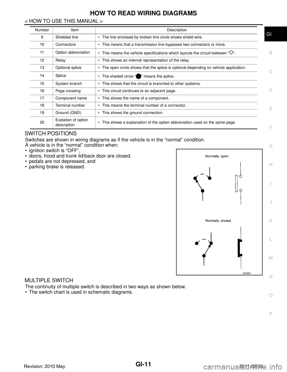
SWITCH POSITIONS
Switches are shown in wiring diagrams as if the vehicle is in the “normal” condition.
A vehicle is in the “normal” condition when:
ignition switch is “OFF”,
doors, hood and trunk lid/back door are closed,
pedals are not depressed, and
parking brake is released.
MULTIPLE SWITCH
The continuity of multiple switch is described in two ways as shown below.
The switch chart is used in schematic diagrams.
9 Shielded line The line enclosed by broken line circle shows shield wire.
10 Connectors This means that a transmission line bypasses two connectors or more.
11 Option abbreviation This means the vehicle specifications which layouts the circuit between “ ”.
12 Relay This shows an internal representation of the relay.
13 Optional splice The open circle shows that the splice is optional depending on vehicle application.
14 Splice The shaded circle “ ” means the splice.
15 System branch This shows that the circuit is branched to other systems.
16 Page crossing This circuit continues to an adjacent page.
17 Component name This shows the name of a component.
18 Terminal number This means the terminal number of a connector.
19 Ground (GND) This shows the ground connection.
20 Explation of option
description This shows a explanation of the option abbreviation used on the same page.
Number Item Description
SGI860
Revision: 2010 May2011 QX56
Page 3451 of 5598
![INFINITI QX56 2011 Factory Service Manual
LAN
SYSTEMLAN-31
< SYSTEM DESCRIPTION > [CAN]
C
D
E
F
G H
I
J
K L
B A
O P
N
Meter display signal
TR
RT
Oil pressure switch signal TR
RT
Position light request signal T R R
Rear fog light status signa INFINITI QX56 2011 Factory Service Manual
LAN
SYSTEMLAN-31
< SYSTEM DESCRIPTION > [CAN]
C
D
E
F
G H
I
J
K L
B A
O P
N
Meter display signal
TR
RT
Oil pressure switch signal TR
RT
Position light request signal T R R
Rear fog light status signa](/manual-img/42/57033/w960_57033-3450.png)
LAN
SYSTEMLAN-31
< SYSTEM DESCRIPTION > [CAN]
C
D
E
F
G H
I
J
K L
B A
O P
N
Meter display signal
TR
RT
Oil pressure switch signal TR
RT
Position light request signal T R R
Rear fog light status signal T R
Rear window defogger con-
trol signal TR
RT
Sleep wake up signal T R R R R R R
Starter control relay signal T R
Starter relay status signal TRR
RT
Starting mode signal T R
Steering lock relay signal TRR
RT
Theft warning horn request
signal TR
Turn indicator signal R T R R
A/C display signal R T
A/C ON signal R T
Ambient temperature signal T R
Blower fan ON signal R T
Distance to empty signal R T
Fuel level low warning sig-
nal RT
Fuel level sensor signal R T
Manual mode shift down
signal RT
Manual mode shift up sig-
nal RT
Manual mode signal R T
Non-manual mode signal R T
Odometer signal R T
Parking brake switch signal R R T R R
Sleep-ready signal RT
RT
RT
Tow mode switch signal R T
Wake up signal RT
RT
Steering angle sensor mal-
function signal RR T R R
Steering angle sensor sig-
nal RR RR T R R
Steering angle speed signal R T R R Signal name
ECM
4WD
ABS
TCM
A-BAG AFS
AV
BCM
CGW
HVAC M&A
STRG
TPMS
IPDM-E
ADPPSB
E-SUS ICC
PWBD
Revision: 2010 May2011 QX56
Page 3675 of 5598

GENERAL MAINTENANCEMA-5
< PERIODIC MAINTENANCE >
C
DE
F
G H
I
J
K L
M B
MA
N
O A
UNDER THE HOOD AND VEHICLE
The maintenance items listed here should
be checked periodically (e.g. each time you check the engine oil or refuel).
Seats Check seat position controls such as seat adjusters, seatback recliner, etc. to
make sure they operate smoothly and that all latches lock securely in every po-
sition. Check that the head restrains move up and down smoothly and that the
locks (if equipped) hold securely in all latched positions. Check that the latches
lock securely for folding-down rear seatbacks. —
Seat belts Check that all parts of the seat belt system (e.g. buckles, anchors, adjusters
and retractors) operate properly and smoothly, and are installed securely.
Check the belt webbing for cuts, fraying, wear or damage. MA-34
Accelerator pedal
Check the pedal for smooth operation and make sure the pedal does not catch
or require uneven effort. Keep the floor mats away from the pedal. —
Brakes Check that the brake does not pull the vehicle to one side when applied. —
Brake pedal and
booster Check the pedal for smooth operation and make sure it has the proper distance
under it when depressed fully. Check the brake booster function. Be sure to
keep the floor mats away from the pedal. BR-7
BR-15
Parking brake
Check that the lever or pedal has the proper travel and make sure that the ve-
hicle is held securely on a fairly steep hill when only the parking brake is ap-
plied. PB-3
Automatic transmis-
sion “Park” mecha-
nismCheck that the lock release button on the selector lever operates properly and
smoothly. On a fairly steep hill check that the vehicle is held securely with the
selector lever in the P (Park) position without applying any brakes.
—
Item
Reference page
Item Reference page
Windshield washer
fluid Check that there is adequate fluid in the tank. —
Engine coolant level Check the coolant level when the engine is cold. MA-12
Radiator and hosesCheck the front of the radiator and clean off any dirt, insects, leaves, etc., that
may have accumulated. Make sure the hoses have no cracks, deformation, de-
terioration or loose connections. MA-16
Brake fluid levels
Make sure that the brake fluid level is between the “MAX” and “MIN” lines on the
reservoir(s). MA-28
Battery
Check the fluid level in each cell. It should be between the “MAX” and “MIN”
lines. Vehicles operated in high temperatures or under severe conditions re-
quire frequent checks of the battery fluid level. PG-159
Engine drive belts
Make sure that no belt is frayed, worn, cracked or oily. MA-12
Engine oil levelCheck the level on the oil level gauge after parking the vehicle on a level spot
and turning off the engine. LU-7
Power steering fluid
level and linesCheck the level on the dipstick with the engine off. Check the lines for improper
attachment, leaks, cracks, etc.
MA-32
Exhaust system
Make sure there are no loose supports, cracks or holes. If the sound of the ex-
haust seems unusual or there is a smell of exhaust fumes, immediately locate
the trouble and correct it. MA-21
Underbody
The underbody is frequently exposed to corrosive substances such as those
used on icy roads or to control dust. It is very important to remove these sub-
stances, otherwise rust will form on the floor pan, frame, fuel lines and around
the exhaust system. At the end of winter, the underbody should be thoroughly
flushed with plain water, being careful to clean those areas where mud and dirt
can easily accumulate. —
Fluid leaks Check under the vehicle for fuel, oil, water or other fluid leaks after the vehicle
has been parked for a while. Water dripping from the air conditioner after use is
normal. If you should notice any leaks or gasoline fumes are evident, check for
the cause and correct it immediately. —
Revision: 2010 May2011 QX56
Page 3698 of 5598

MA-28
< PERIODIC MAINTENANCE >
CHASSIS MAINTENANCE
BRAKE FLUID LEVEL AND LEAKS : Inspection
INFOID:0000000006220939
Check that the fluid level in the sub tank is within the specified range (MAX – MIN lines).
CAUTION:
Turn OFF the ignition switch an d depress the brake pedal 20 times or more to check brake fluid level.
NOTE:
Since brake fluid is in the accumulator in pressurized condition, the reservoir tank brake fluid level should be
lower than the MAX line.
Visually check for any brake fluid leakage around the reservoir tank.
Check the brake system for any leakage if the fl uid level is extremely low (lower than MIN).
Check the brake system for fluid leakage if the warn ing lamp remains illuminated even after the parking
brake is released.
Check the sub tank for the mixing of foreign ma tter (e.g. dust) and oils other than brake fluid.
BRAKE LINES AND CABLES
BRAKE LINES AND CABLES : InspectionINFOID:0000000006220940
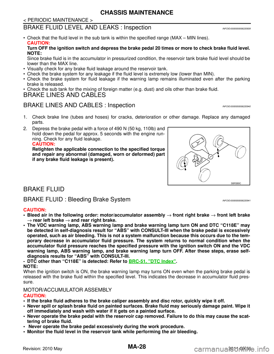
1. Check brake line (tubes and hoses) for cracks, deterioration or other damage. Replace any damaged
parts.
2. Depress the brake pedal with a force of 490 N (50 kg, 110lb) and hold down the pedal for approx. 5 seconds with the engine run-
ning. Check for any fluid leakage.
CAUTION:
Retighten the applicable conn ection to the specified torque
and repair any abnormal (damag ed, worn or deformed) part
if any brake fluid leakage is present).
BRAKE FLUID
BRAKE FLUID : Bleeding Brake SystemINFOID:0000000006220941
CAUTION:
Bleed air in the following order: motor/accumulator assembly → front right brake → front left brake
→ rear left brake → and rear right brake.
The VDC warning lamp, ABS warning lamp and br ake warning lamp turn ON and DTC “C118E” may
be detected in self-diagnosis r esult for “ABS” with CONSULT-II I when the brake pedal is excessively
operated, such as air bleeding. Thi s is not a system malfunction becau se this occurs due to the tem-
porary decrease in accumulator fl uid pressure. The system returns to normal condition when the
accumulator fluid pressure reaches the specified pressu re with the ignition switch ON and the VDC
warning lamp, ABS warning lamp, and brake warnin g lamp turn OFF. After these steps, erase self-
diagnosis results for “ABS” with CONSULT-III.
- DTC other than “C118E” is detected: Refer to BRC-51, "
DTC Index".
NOTE:
When the ignition switch is ON, the brake warning la mp may turns ON even when the parking brake pedal is
released with the brake fluid within the specified level. This indicates the decrease in accumulator fluid pres-
sure.
MOTOR/ACCUMULATOR ASSEMBLY
CAUTION:
If the brake fluid adheres to the brake caliper assembly and disc rotor, quickly wipe it off.
Never spill or splash brake fluid on painted surfaces. Brake fluid may seriously damage paint. Wipe it
off immediately and wash with wate r if it gets on a painted surface.
Never operate the brake pedal with the reservoir cap removed. Failure to do this may cause the scat-
tering of brake fluid.
Never operate the brake pedal excessively during the work procedure.
Monitor the fluid level in the reservoir tank while performing the air bleeding.
SBR389C
Revision: 2010 May2011 QX56
Page 3745 of 5598

MWI-2
DIAGNOSIS SYSTEM (COMBINATION
METER) ..............................................................
29
On Board Diagnosis Function .............................. ...29
CONSULT-III Function ...........................................30
ECU DIAGNOSIS INFORMATION ..............35
COMBINATION METER ................................. ...35
Reference Value .................................................. ...35
Fail-Safe .................................................................42
DTC Index ..............................................................43
IPDM E/R ...........................................................44
List of ECU Reference ......................................... ...44
WIRING DIAGRAM .....................................45
METER SYSTEM ............................................ ...45
Wiring Diagram .................................................... ...45
CLOCK ...............................................................55
Wiring Diagram .................................................... ...55
BASIC INSPECTION ...................................57
DIAGNOSIS AND REPAIR WORKFLOW
(METER SYSTEM ) .......................................... ...
57
Work flow ............................................................. ...57
DTC/CIRCUIT DIAGNOSIS ...................... ...59
U1000 CAN COMM CIRCUIT ......................... ...59
Description ........................................................... ...59
DTC Logic ...............................................................59
Diagnosis Procedure .............................................59
U1010 CONTROL UNIT (CAN) .........................60
Description ........................................................... ...60
DTC Logic ...............................................................60
Diagnosis Procedure ..............................................60
B2205 VEHICLE SPEED ...................................61
Description ........................................................... ...61
DTC Logic ...............................................................61
Diagnosis Procedure .............................................61
B2267 ENGINE SPEED .....................................62
Description ........................................................... ...62
DTC Logic ...............................................................62
Diagnosis Procedure ..............................................62
B2268 WATER TEMP ........................................63
Description ........................................................... ...63
DTC Logic ...............................................................63
Diagnosis Procedure ..............................................63
POWER SUPPLY AND GROUND CIRCUIT .....64
COMBINATION METER ........................................ ...64
COMBINATION METER : Diagnosis Procedure ....64
TRIP RESET AND ILLUMINATION CON-
TROL SWITCH SIGNAL CIRCUIT ....................
65
Diagnosis Procedure ............................................ ...65
Component Inspection ............................................66
TRIP COMPUTER SWITCH SIGNAL CIRCUIT
...
67
Diagnosis Procedure ............................................ ...67
Component Inspection ............................................68
FUEL LEVEL SENSOR SIGNAL CIRCUIT .......69
Component Function Check ................................ ...69
Diagnosis Procedure ..............................................69
Component Inspection ............................................70
OIL PRESSURE SWITCH SIGNAL CIRCUIT ...71
Component Function Check ...................................71
Diagnosis Procedure ...............................................71
Component Inspection ............................................71
WASHER LEVEL SWITCH SIGNAL CIRCUIT ...73
Diagnosis Procedure ............................................ ...73
Component Inspection ............................................73
A/C AUTO AMP. CONNECTION RECOGNI-
TION SIGNAL CIRCUIT ....................................
74
Diagnosis Procedure ........................................... ...74
SYMPTOM DIAGNOSIS ............................75
THE FUEL GAUGE INDICATOR DOES NOT
OPERATE ....................................................... ...
75
Description ........................................................... ...75
Diagnosis Procedure ...............................................75
THE TRIP RESET AND ILLUMINATION CON-
TROL SWITCH IS INOPERATIVE ....................
76
Description ........................................................... ...76
Diagnosis Procedure ...............................................76
THE TRIP COMPUTER SWITCH IS INOPER-
ATIVE .................................................................
77
Description ........................................................... ...77
Diagnosis Procedure ...............................................77
THE OIL PRESSURE WARNING LAMP
DOES NOT TURN ON .................................... ...
78
Description ........................................................... ...78
Diagnosis Procedure ...............................................78
THE OIL PRESSURE WARNING LAMP
DOES NOT TURN OFF .................................. ...
79
Description ........................................................... ...79
Diagnosis Procedure ...............................................79
THE PARKING BRAKE RELEASE WARNING
CONTINUES DISPLAYING, OR DOES NOT
DISPLAY ............................................................
80
Description ........................................................... ...80
Diagnosis Procedure ...............................................80
Revision: 2010 May2011 QX56
Page 3749 of 5598

MWI-6
< SYSTEM DESCRIPTION >
COMPONENT PARTS
SYSTEM DESCRIPTION
COMPONENT PARTS
METER SYSTEM
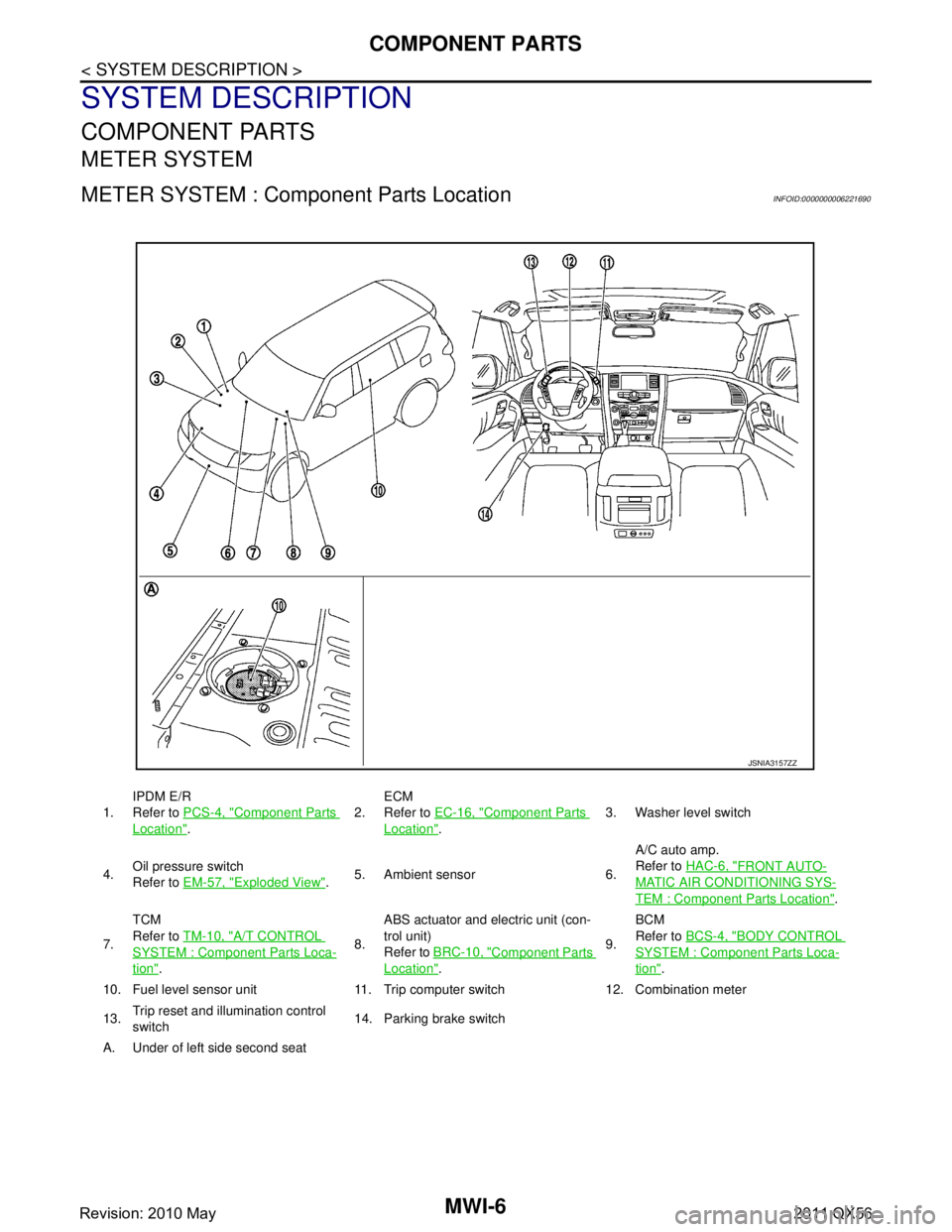
METER SYSTEM : Component Parts LocationINFOID:0000000006221690
1.IPDM E/R
Refer to
PCS-4, "Component Parts
Location". 2.
ECM
Refer to
EC-16, "
Component Parts
Location". 3. Washer level switch
4. Oil pressure switch
Refer to
EM-57, "
Exploded View".5. Ambient sensor 6. A/C auto amp.
Refer to
HAC-6, "
FRONT AUTO-
MATIC AIR CONDITIONING SYS-
TEM : Component Parts Location".
7. TCM
Refer to
TM-10, "
A/T CONTROL
SYSTEM : Componen t Parts Loca-
tion". 8.ABS actuator and electric unit (con-
trol unit)
Refer to
BRC-10, "
Component Parts
Location". 9.BCM
Refer to
BCS-4, "
BODY CONTROL
SYSTEM : Component Parts Loca-
tion".
10. Fuel level sensor unit 11. Trip computer switch 12. Combination meter
13. Trip reset and illumination control
switch 14. Parking brake switch
A. Under of left side second seat
JSNIA3157ZZ
Revision: 2010 May2011 QX56