2011 INFINITI QX56 ground
[x] Cancel search: groundPage 5502 of 5598
WT-52
< DTC/CIRCUIT DIAGNOSIS >
LOW TIRE PRESSURE WARNING LAMP
LOW TIRE PRESSURE WARNING LAMP
Component Function CheckINFOID:0000000006225531
1.CHECK LOW TIRE PRESSURE WARNING LAMP OPERATION
Check that the low tire pressure warning lamp is tu rned OFF after turns ON for approximately 1 second, when
the ignition switch is turned ON.
Is the inspection result normal?
YES >> INSPECTION END
NO >> Proceed to WT-52, "
Diagnosis Procedure".
Diagnosis ProcedureINFOID:0000000006225532
1.CHECK LOW TIRE PRESSURE WARNING CONT ROL UNIT POWER SUPPLY AND GROUND CIRCUIT
Perform the trouble diagnosis for power supply and ground circuit. Refer to WT-51, "
Diagnosis Procedure".
Is the inspection result normal?
YES >> GO TO 2.
NO >> Repair or replace error-detected parts.
2.PERFORM LOW TIRE PRESSURE WARNI NG CONTROL UNIT SELF-DIAGNOSIS
With CONSULT-III
1. Drive for several minutes at a s peed of 40 km/h (25 MPH) or more.
2. Stop the vehicle.
3. Perform self-diagnosis for “AIR PRESSURE MONITOR”.
Is any DTC detected?
YES >> Perform trouble diagnosis for detected DTC. Refer to WT-18, "DTC Index".
NO >> GO TO 3.
3.CHECK LOW TIRE PRESSURE WARNING LAMP SIGNAL
With CONSULT-III
1. Turn the ignition switch ON.
CAUTION:
Never start engine.
2. Select “DATA MONITOR” for “AIR PR ESSURE MONITOR” with CONSULT-III.
3. Read out the value of “WARNING LAMP”. For low tire pressure warning lamp condition, refer to “LOW TIRE PRESSURE WARNING LA MP CONTROL CONDITION” in WT-9, "
System Description".
Does the data monitor display change normal?
YES >> GO TO 4.
NO >> Replace the low tire pressure warning control unit. Refer to WT-65, "
Removal and Installation".
4.CHECK COMBINATION METER POWER SUPPLY CIRCUIT
Perform the trouble diagnosis for combination meter power supply circuit. Refer to MWI-64, "
COMBINATION
METER : Diagnosis Procedure".
Is the inspection result normal?
YES >> INSPECTION END
NO >> Repair or replace error-detected parts.
Revision: 2010 May2011 QX56
Page 5507 of 5598
LOW TIRE PRESSURE WARNING LAMP DOES NOT TURN OFFWT-57
< SYMPTOM DIAGNOSIS >
C
DF
G H
I
J
K L
M A
B
WT
N
O P
LOW TIRE PRESSURE WARNING LAMP DOES NOT TURN OFF
DescriptionINFOID:0000000006225536
The low tire pressure warning lamp does not turn OFF after several seconds is passed after engine starts.
Diagnosis ProcedureINFOID:0000000006225537
1.CHECK TIRE PRESSURE
1. Turn the ignition switch ON. CAUTION:
Never start the engine.
2. Check the tire pressure for all wheels and adjust to the specified value. Refer to WT-69, "
Tire Air Pres-
sure".
Is the inspection result normal?
YES >> GO TO 2.
NO >> Inspect or repair the tires or wheels.
2.CHECK LOW TIRE PRE SSURE WARNING LAMP
Check low tire pressure warning lamp display.
Does not low tire pressure warning lamp turn OFF?
YES >> GO TO 3.
NO >> INSPECTION END
3.CHECK DTC WITH LOW TIRE PR ESSURE WARNING CONTROL UNIT
With CONSULT-III
Perform self-diagnosis for “AIR PRESSURE MONITOR”.
Is any DTC detected?
YES >> Perform the diagnosis applicable to the displayed DTC. Refer to WT-18, "DTC Index".
NO >> GO TO 4.
4.CHECK LOW TIRE PRESSURE WARNING CONT ROL UNIT POWER SUPPLY AND GROUND CIRCUIT
Perform the trouble diagnosis for power supply and ground circuit. Refer to WT-51, "
Diagnosis Procedure".
Is the inspection result normal?
YES >> Replace low tire pressure warning control unit. Refer to WT-65, "Removal and Installation".
NO >> Repair or replace error-detected parts.
Revision: 2010 May2011 QX56
Page 5521 of 5598

WW-2
FRONT WIPER MOTOR GROUND CIRCUIT ...39
Diagnosis Procedure ..............................................39
LIGHT & RAIN SENSOR ...................................40
Component Function Check ................................ ...40
Diagnosis Procedure ..............................................40
WASHER SWITCH ............................................42
Component Inspection ......................................... ...42
REAR WIPER MOTOR CIRCUIT ......................43
Component Function Check ................................ ...43
Diagnosis Procedure ..............................................43
REAR WIPER AUTO STOP SIGNAL CIRCUIT
...
45
Component Function Check ................................ ...45
Diagnosis Procedure ..............................................45
HEADLAMP WASHER RELAY .........................46
Component Inspection ......................................... ...46
HEADLAMP WASHER CIRCUIT ......................47
Component Function Check ................................ ...47
Diagnosis Procedure ..............................................47
SYMPTOM DIAGNOSIS .............................49
WIPER AND WASHER SYSTEM SYMPTOMS
...
49
Symptom Table ................................................... ...49
NORMAL OPERATING CONDITION ................52
Description ........................................................... ...52
FRONT WIPER DOES NOT OPERATE ............53
Description ........................................................... ...53
Diagnosis Procedure ..............................................53
REMOVAL AND INSTALLATION ...............55
HEADLAMP WASHER NOZZLE AND TUBE ...55
Exploded View ..................................................... ...55
Hydraulic Layout .....................................................55
Removal and Installation ........................................56
Inspection ...............................................................56
WASHER TANK ............................................. ...58
Exploded View ..................................................... ...58
Removal and Installation ........................................58
WASHER PUMP ................................................60
Exploded View ..................................................... ...60
Removal and Installation .........................................60
HEADLAMP WASHER PUMP ..........................61
Exploded View ..................................................... ...61
Removal and Installation .........................................61
WASHER LEVEL SWITCH ...............................62
Removal and Installation ...................................... ...62
FRONT WASHER NOZZLE AND TUBE ...........63
Exploded View ..................................................... ...63
Hydraulic Layout .....................................................63
Removal and Installation .........................................64
Inspection and Adjustment ......................................64
FRONT WIPER ARM .........................................66
Exploded View ..................................................... ...66
Removal and Installation .........................................66
Adjustment ..............................................................66
FRONT WIPER BLADE .....................................68
Exploded View ..................................................... ...68
Removal and Installation .........................................68
Replacement ...........................................................68
FRONT WIPER DRIVE ASSEMBLY .................70
Exploded View ..................................................... ...70
Removal and Installation .........................................70
Disassembly and Assembly ....................................71
LIGHT & RAIN SENSOR ...................................72
Exploded View ..................................................... ...72
Removal and Installation .........................................72
WIPER AND WASHER SWITCH ......................73
Exploded View ..................................................... ...73
REAR WIPER ARM ...........................................74
Exploded View ..................................................... ...74
Removal and Installation .........................................74
Adjustment ..............................................................74
REAR WIPER MOTOR ......................................76
Exploded View ..................................................... ...76
Removal and Installation .........................................76
REAR WASHER NOZZLE AND TUBE .............77
Hydraulic Layout .................................................. ...77
Removal and Installation .........................................77
Inspection and Adjustment ......................................78
Revision: 2010 May2011 QX56
Page 5525 of 5598
WW-6
< SYSTEM DESCRIPTION >
COMPONENT PARTS
Component Description
INFOID:0000000006300449
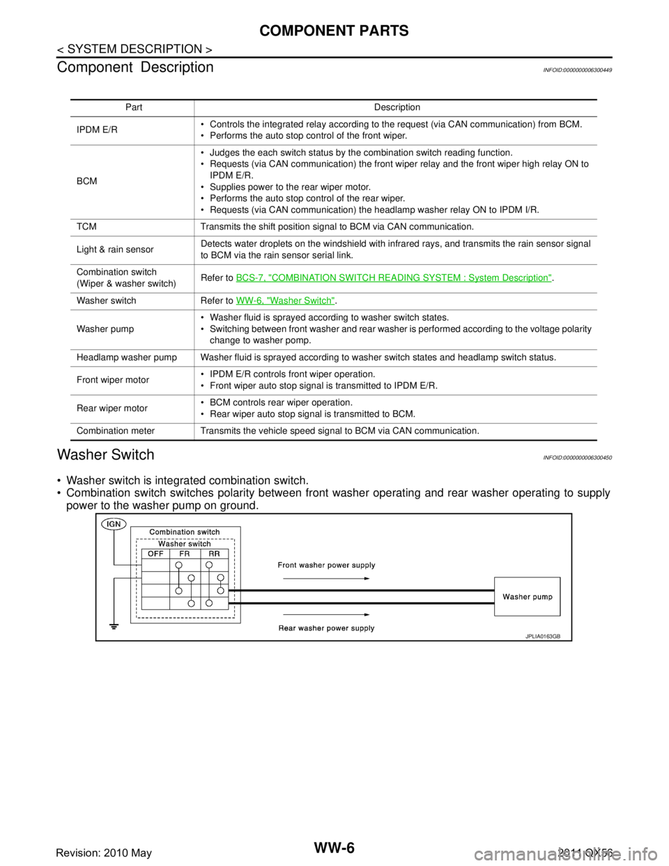
Washer SwitchINFOID:0000000006300450
Washer switch is integrated combination switch.
Combination switch switches polarity between front washer operating and rear washer operating to supply
power to the washer pump on ground.
Part Description
IPDM E/R Controls the integrated relay according to the request (via CAN communication) from BCM.
Performs the auto stop control of the front wiper.
BCM Judges the each switch status by the combination switch reading function.
Requests (via CAN communication) the front wiper relay and the front wiper high relay ON to
IPDM E/R.
Supplies power to the rear wiper motor.
Performs the auto stop control of the rear wiper.
Requests (via CAN communication) the headlamp washer relay ON to IPDM I/R.
TCM Transmits the shift position signal to BCM via CAN communication.
Light & rain sensor Detects water droplets on the windshield with infrared rays, and transmits the rain sensor signal
to BCM via the rain sensor serial link.
Combination switch
(Wiper & washer switch) Refer to
BCS-7, "
COMBINATION SWITCH READING S YSTEM : System Description".
Washer switch Refer to WW-6, "
Washer Switch".
Washer pump Washer fluid is sprayed according to washer switch states.
Switching between front washer and rear washer is performed according to the voltage polarity
change to washer pomp.
Headlamp washer pump Washer fluid is sprayed according to washer switch states and headlamp switch status.
Front wiper motor IPDM E/R controls front wiper operation.
Front wiper auto stop signal is transmitted to IPDM E/R.
Rear wiper motor BCM controls rear wiper operation.
Rear wiper auto stop signal is transmitted to BCM.
Combination meter Transmits the vehicle speed signal to BCM via CAN communication.
JPLIA0163GB
Revision: 2010 May2011 QX56
Page 5528 of 5598
SYSTEMWW-9
< SYSTEM DESCRIPTION >
C
DE
F
G H
I
J
K
M A
B
WW
N
O P
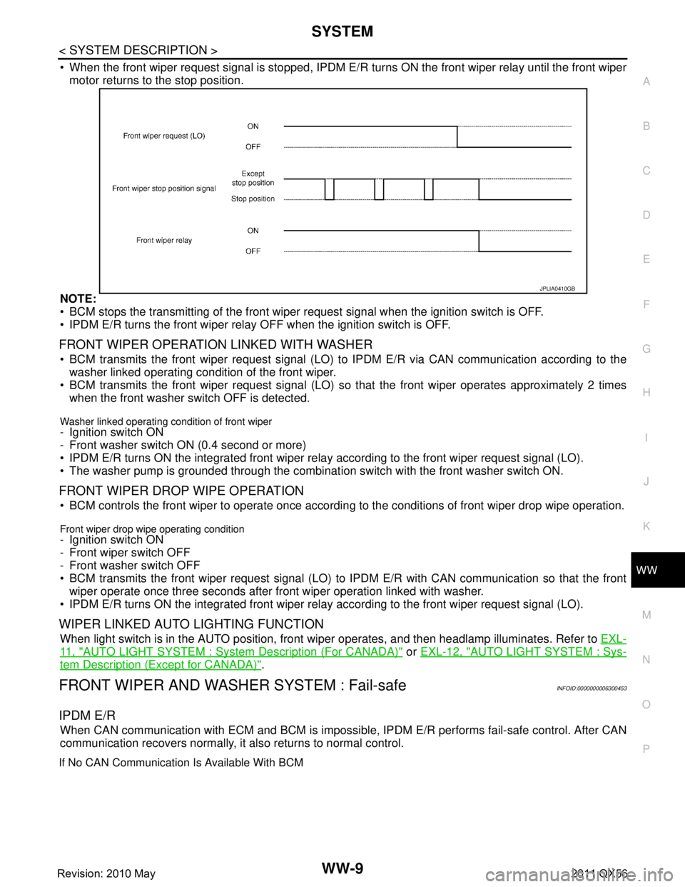
When the front wiper request signal is stopped, IPDM E/R turns ON the front wiper relay until the front wiper
motor returns to the stop position.
NOTE:
BCM stops the transmitting of the front wiper request signal when the ignition switch is OFF.
IPDM E/R turns the front wiper relay OFF when the ignition switch is OFF.
FRONT WIPER OPERATION LINKED WITH WASHER
BCM transmits the front wiper request signal (LO) to IPDM E/R via CAN communication according to the
washer linked operating condition of the front wiper.
BCM transmits the front wiper request signal (LO) so that the front wiper operates approximately 2 times
when the front washer switch OFF is detected.
Washer linked operating condition of front wiper
- Ignition switch ON
- Front washer switch ON (0.4 second or more)
IPDM E/R turns ON the integrated front wiper rela y according to the front wiper request signal (LO).
The washer pump is grounded through the combinati on switch with the front washer switch ON.
FRONT WIPER DROP WIPE OPERATION
BCM controls the front wiper to operate once according to the conditions of front wiper drop wipe operation.
Front wiper drop wipe operating condition
- Ignition switch ON
- Front wiper switch OFF
- Front washer switch OFF
BCM transmits the front wiper request signal (LO) to IPDM E/R with CAN communication so that the front
wiper operate once three seconds after fr ont wiper operation linked with washer.
IPDM E/R turns ON the integrated front wiper rela y according to the front wiper request signal (LO).
WIPER LINKED AUTO LIGHTING FUNCTION
When light switch is in the AUTO position, front wiper operates, and then headlamp illuminates. Refer to EXL-
11 , "AUTO LIGHT SYSTEM : System Description (For CANADA)" or EXL-12, "AUTO LIGHT SYSTEM : Sys-
tem Description (Except for CANADA)".
FRONT WIPER AND WASHER SYSTEM : Fail-safeINFOID:0000000006300453
IPDM E/R
When CAN communication with ECM and BCM is impossible, IPDM E/R performs fail-safe control. After CAN
communication recovers normally, it also returns to normal control.
If No CAN Communication Is Available With BCM
JPLIA0410GB
Revision: 2010 May2011 QX56
Page 5531 of 5598

WW-12
< SYSTEM DESCRIPTION >
SYSTEM
- Rear washer switch ON (0.4 second or more)
The washer pump is grounded through the combination switch with the rear washer switch ON.
REAR WIPER OPERATION LINKED WITH REVERSE (WITH RAIN SENSOR)
BCM controls rear wiper to operate once according to the conditions of rear wiper operation linked with
reverse.
Condition of rear wiper operation linked with reverse - Ignition switch ON
- Front wiper switch: LO, HI or AUTO, and the front wiper auto operation ON judgement.
- Rear wiper switch OFF
- Selector lever “R”
TCM transmits the shift position signal to BCM thr ough the CAN communication line when the selector lever
is shifted to "R".
BCM supplies power to the rear wiper motor when receiving the shift position signal.
REAR WIPER OPERATION LINKED WITH REVERSE (WITHOUT RAIN SENSOR)
BCM controls rear wiper to operate once according to the conditions of rear wiper operation linked with
reverse.
Condition of rear wiper operation linked with reverse
- Ignition switch ON
- Front wiper switch: LO, HI or INT.
- Rear wiper switch OFF
- Selector lever “R”
TCM transmits the shift position signal to BCM thr ough the CAN communication line when the selector lever
is shifted to "R".
BCM supplies power to the rear wiper motor when receiving the shift position signal.
REAR WIPER DROP WIPE OPERATION
BCM controls the rear wiper to operate once acco rding to the rear wiper drop wipe operating condition.
Rear wiper drop wipe operating condition- Ignition switch ON
- Rear wiper switch OFF
- Rear washer switch OFF
BCM controls the rear wiper so that it operates once approximately three seconds later after the washer
interlocking operation of the rear wiper.
REAR WIPER AND WASHER SYSTEM : Fail SafeINFOID:0000000006300459
REAR WIPER MOTOR PROTECTION
BCM detects the rear wiper stopping position ac cording to the rear wiper auto stop signal.
When the rear wiper auto stop signal does not change more than 5 seconds while driving the rear wiper, BCM
stops power supply to protect the rear wiper motor.
Condition of cancellation
1. Pass more than 1 minute after the rear wiper stop.
2. Operate the rear wiper switch.
HEADLAMP WASHER SYSTEM
Revision: 2010 May2011 QX56
Page 5538 of 5598
DIAGNOSIS SYSTEM (IPDM E/R)WW-19
< SYSTEM DESCRIPTION >
C
DE
F
G H
I
J
K
M A
B
WW
N
O P
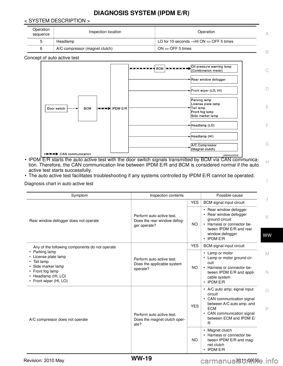
Concept of auto active test
IPDM E/R starts the auto active test with the door
switch signals transmitted by BCM via CAN communica-
tion. Therefore, the CAN communication line between IPDM E/R and BCM is considered normal if the auto
active test starts successfully.
The auto active test facilitates troubleshooting if any systems controlled by IPDM E/R cannot be operated.
Diagnosis chart in auto active test
5 Headlamp LO for 10 seconds →HI ON ⇔ OFF 5 times
6 A/C compressor (magnet clutch) ON ⇔ OFF 5 times
Operation
sequence Inspection location Operation
JMMIA0492GB
Symptom Inspection contents Possible cause
Rear window defogger does not operate Perform auto active test.
Does the rear window defog-
ger operate?YES BCM signal input circuit
NO Rear window defogger
Rear window defogger
ground circuit
Harness or connector be- tween IPDM E/R and rear
window defogger
IPDM E/R
Any of the following components do not operate
Parking lamp
License plate lamp
Tail lamp
Side marker lamp
Front fog lamp
Headlamp (HI, LO)
Front wiper (HI, LO) Perform auto active test.
Does the applicable system
operate?YES BCM signal input circuit
NO Lamp or motor
Lamp or motor ground cir-
cuit
Harness or connector be- tween IPDM E/R and appli-
cable system
IPDM E/R
A/C compressor does not operate Perform auto active test.
Does the magnet clutch oper-
ate?YES
A/C auto amp. signal input
circuit
CAN communication signal
between A/C auto amp. and
ECM
CAN communication signal
between ECM and IPDM E/
R
NO Magnet clutch
Harness or connector be-
tween IPDM E/R and mag-
net clutch
IPDM E/R
Revision: 2010 May2011 QX56
Page 5555 of 5598
WW-36
< DTC/CIRCUIT DIAGNOSIS >
FRONT WIPER MOTOR LO CIRCUIT
FRONT WIPER MOTOR LO CIRCUIT
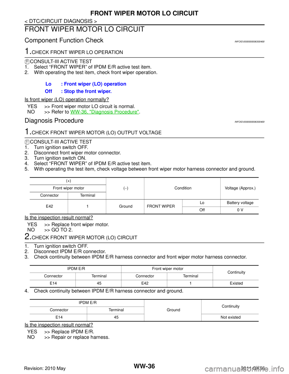
Component Function CheckINFOID:0000000006300468
1.CHECK FRONT WIPER LO OPERATION
CONSULT-III ACTIVE TEST
1. Select “FRONT WIPER” of IPDM E/R active test item.
2. With operating the test item, check front wiper operation.
Is front wiper (LO) operation normally?
YES >> Front wiper motor LO circuit is normal.
NO >> Refer to WW-36, "
Diagnosis Procedure".
Diagnosis ProcedureINFOID:0000000006300469
1.CHECK FRONT WIPER MOTOR (LO) OUTPUT VOLTAGE
CONSULT-III ACTIVE TEST
1. Turn ignition switch OFF.
2. Disconnect front wiper motor connector.
3. Turn ignition switch ON.
4. Select “FRONT WIPER” of IPDM E/R active test item.
5. With operating the test item, check voltage between front wiper motor harness connector and ground.
Is the inspection result normal?
YES >> Replace front wiper motor.
NO >> GO TO 2.
2.CHECK FRONT WIPER MOTOR (LO) CIRCUIT
1. Turn ignition switch OFF.
2. Disconnect IPDM E/R connector.
3. Check continuity between IPDM E/R harness connector and front wiper motor harness connector.
4. Check continuity between IP DM E/R harness connector and ground.
Is the inspection result normal?
YES >> Replace IPDM E/R.
NO >> Repair or replace harness. Lo : Front wiper (LO) operation
Off : Stop the front wiper.
(+)
(− ) Condition Voltage (Approx.)
Front wiper motor
Connector Terminal
E42 1 Ground FRONT WIPER Lo Battery voltage
Off 0 V
IPDM E/R Front wiper motor Continuity
Connector Terminal Connector Terminal
E14 45 E42 1 Existed
IPDM E/R GroundContinuity
Connector Terminal
E14 45 Not existed
Revision: 2010 May2011 QX56