Page 5556 of 5598

FRONT WIPER MOTOR HI CIRCUITWW-37
< DTC/CIRCUIT DIAGNOSIS >
C
DE
F
G H
I
J
K
M A
B
WW
N
O P
FRONT WIPER MOTOR HI CIRCUIT
Component Function CheckINFOID:0000000006300470
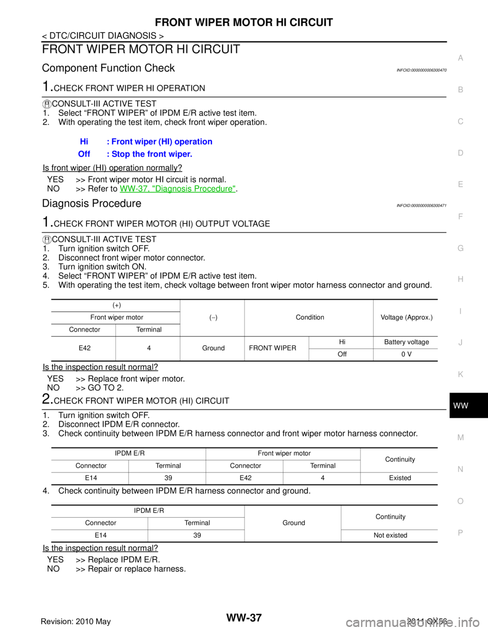
1.CHECK FRONT WIPER HI OPERATION
CONSULT-III ACTIVE TEST
1. Select “FRONT WIPER” of IPDM E/R active test item.
2. With operating the test item, check front wiper operation.
Is front wiper (HI) operation normally?
YES >> Front wiper motor HI circuit is normal.
NO >> Refer to WW-37, "
Diagnosis Procedure".
Diagnosis ProcedureINFOID:0000000006300471
1.CHECK FRONT WIPER MOTOR (HI) OUTPUT VOLTAGE
CONSULT-III ACTIVE TEST
1. Turn ignition switch OFF.
2. Disconnect front wiper motor connector.
3. Turn ignition switch ON.
4. Select “FRONT WIPER” of IPDM E/R active test item.
5. With operating the test item, check voltage between front wiper motor harness connector and ground.
Is the inspection result normal?
YES >> Replace front wiper motor.
NO >> GO TO 2.
2.CHECK FRONT WIPER MOTOR (HI) CIRCUIT
1. Turn ignition switch OFF.
2. Disconnect IPDM E/R connector.
3. Check continuity between IPDM E/R harness connector and front wiper motor harness connector.
4. Check continuity between IPDM E/R harness connector and ground.
Is the inspection result normal?
YES >> Replace IPDM E/R.
NO >> Repair or replace harness. Hi : Front wiper (HI) operation
Off : Stop the front wiper.
(+)
(− ) Condition Voltage (Approx.)
Front wiper motor
Connector Terminal
E42 4 Ground FRONT WIPER Hi Battery voltage
Off 0 V
IPDM E/R Front wiper motor Continuity
Connector Terminal Connector Terminal
E1439E42 4Existed
IPDM E/R GroundContinuity
Connector Terminal
E14 39 Not existed
Revision: 2010 May2011 QX56
Page 5557 of 5598

WW-38
< DTC/CIRCUIT DIAGNOSIS >
FRONT WIPER AUTO STOP SIGNAL CIRCUIT
FRONT WIPER AUTO STOP SIGNAL CIRCUIT
Component Function CheckINFOID:0000000006300472
1.CHECK FRONT WIPER (AUTO STOP) SIGNAL
CONSULT-III DATA MONITOR
1. Select “WIP AUTO STOP” of IPDM E/R data monitor item.
2. Operate the front wiper.
3. With the front wiper operation, check the monitor status.
Is the status of item normal?
YES >> Auto stop signal circuit is normal.
NO >> Refer to WW-38, "
Diagnosis Procedure".
Diagnosis ProcedureINFOID:0000000006300473
1.CHECK IPDM E/R OUTPUT VOLTAGE
1. Turn ignition switch OFF.
2. Disconnect front wiper motor connector.
3. Turn ignition switch ON.
4. Check voltage between front wiper motor harness connector and ground.
Is the inspection result normal?
YES >> Replace front wiper motor.
NO >> GO TO 2.
2.CHECK FRONT WIPER MOTO R (AUTO STOP) CIRCUIT
1. Turn ignition switch OFF.
2. Disconnect IPDM E/R connector.
3. Check continuity between IPDM E/R harness connector and front wiper motor harness connector.
4. Check continuity between IP DM E/R harness connector and ground.
Is the inspection result normal?
YES >> Replace IPDM E/R.
NO >> Repair or replace harness.
Monitor item Condition Monitor status
WIP AUTO STOP Front wiper motor Stop position STOP P
Except stop position ACT P
(+)
(− ) Voltage (Approx.)
Front wiper motor
Connector Terminal E42 5 Ground Battery voltage
IPDM E/R Front wiper motor Continuity
Connector Terminal Connector Terminal
E13 25 E42 5 Existed
IPDM E/R GroundContinuity
Connector Terminal
E13 25 Not existed
Revision: 2010 May2011 QX56
Page 5558 of 5598
FRONT WIPER MOTOR GROUND CIRCUITWW-39
< DTC/CIRCUIT DIAGNOSIS >
C
DE
F
G H
I
J
K
M A
B
WW
N
O P
FRONT WIPER MOTOR GROUND CIRCUIT
Diagnosis ProcedureINFOID:0000000006300474
1.CHECK FRONT WIPER MOTOR GROUND CIRCUIT
1. Turn ignition switch OFF.
2. Disconnect front wiper motor connector.
3. Check continuity between front wiper motor harness connector and ground.
Is the inspection result normal?
YES >> INSPECTION END
NO >> Repair or replace harness.
Front wiper motor
GroundContinuity
Connector Terminal
E42 2 Existed
Revision: 2010 May2011 QX56
Page 5559 of 5598

WW-40
< DTC/CIRCUIT DIAGNOSIS >
LIGHT & RAIN SENSOR
LIGHT & RAIN SENSOR
Component Function CheckINFOID:0000000006300475
1.CHECK FRONT WIPER AUTO OPERATION
1. Clean light & rain sensor detection area of windshield fully.
2. When the front wiper switch is turned to AUTO pos ition, front wiper operates once regardless of a rainy
condition.
Is front wiper (AUTO) operation normally?
YES >> Light & rain sensor circuit is normal.
NO >> Refer to WW-40, "
Diagnosis Procedure".
Diagnosis ProcedureINFOID:0000000006300476
1.CHECK LIGHT & RAIN SENSOR FUSE
1. Turn the ignition switch OFF.
2. Check that the light & rain sensor 10A fuse (#6) is not fusing.
Is the fuse fusing?
YES >> Replace the fuse after repairing the applicable circuit.
NO >> GO TO 2.
2.CHECK LIGHT & RAIN SENSOR POWER SUPPLY
1. Disconnect light & rain sensor connector.
2. Check voltage between light & rain sensor harness connector and ground.
Is the measurement value normal?
YES >> GO TO 3.
NO >> Repair or replace harness.
3.CHECK LIGHT & RAIN SENSOR GROUND CIRCUIT
Check continuity between light & ra in sensor harness connector and ground.
Does continuity exist?
YES >> GO TO 4.
NO >> Repair or replace harness.
4.CHECK LIGHT & RAIN SENSOR SIGNAL
1. Connect light & rain sensor connector.
2. Turn ignition switch ON.
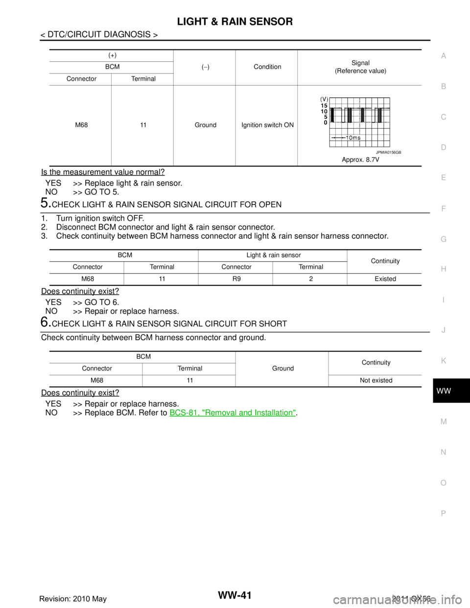
3. Check signal between BCM harness connector and ground with oscilloscope.
(+)
(− ) Voltage (Approx.)
Light & rain sensor
Connector Terminal R9 1 Ground Battery voltage
Light & rain sensor GroundContinuity
Connector Terminal
R9 3 Existed
Revision: 2010 May2011 QX56
Page 5560 of 5598

LIGHT & RAIN SENSORWW-41
< DTC/CIRCUIT DIAGNOSIS >
C
DE
F
G H
I
J
K
M A
B
WW
N
O P
Is the measurement value normal?
YES >> Replace light & rain sensor.
NO >> GO TO 5.
5.CHECK LIGHT & RAIN SENSOR SIGNAL CIRCUIT FOR OPEN
1. Turn ignition switch OFF.
2. Disconnect BCM connector and light & rain sensor connector.
3. Check continuity between BCM harness connecto r and light & rain sensor harness connector.
Does continuity exist?
YES >> GO TO 6.
NO >> Repair or replace harness.
6.CHECK LIGHT & RAIN SENSOR SIGNAL CIRCUIT FOR SHORT
Check continuity between BCM harness connector and ground.
Does continuity exist?
YES >> Repair or replace harness.
NO >> Replace BCM. Refer to BCS-81, "
Removal and Installation".
(+)
(− ) Condition Signal
(Reference value)
BCM
Connector Terminal
M68 11 Ground Ignition switch ON Approx. 8.7V
JPMIA0156GB
BCM Light & rain sensorContinuity
Connector Terminal Connector Terminal
M68 11 R9 2 Existed
BCM GroundContinuity
Connector Terminal
M68 11 Not existed
Revision: 2010 May2011 QX56
Page 5562 of 5598

REAR WIPER MOTOR CIRCUITWW-43
< DTC/CIRCUIT DIAGNOSIS >
C
DE
F
G H
I
J
K
M A
B
WW
N
O P
REAR WIPER MOTOR CIRCUIT
Component Function CheckINFOID:0000000006300478
1.CHECK REAR WIPER ON OPERATION
CONSULT-III ACTIVE TEST
1. Select “RR WIPER” of BCM active test item.
2. With operating the test item, check rear wiper operation.
Is rear wiper operation normally?
YES >> Rear wiper motor circuit is normal.
NO >> Refer to WW-43, "
Diagnosis Procedure".
Diagnosis ProcedureINFOID:0000000006300479
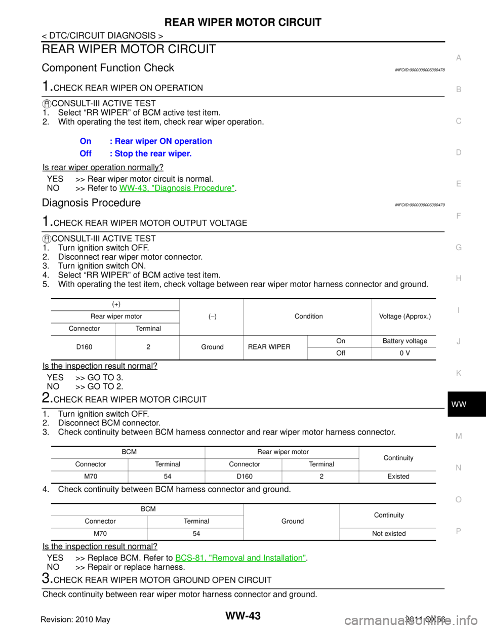
1.CHECK REAR WIPER MOTOR OUTPUT VOLTAGE
CONSULT-III ACTIVE TEST
1. Turn ignition switch OFF.
2. Disconnect rear wiper motor connector.
3. Turn ignition switch ON.
4. Select “RR WIPER” of BCM active test item.
5. With operating the test item, check voltage between rear wiper motor harness connector and ground.
Is the inspection result normal?
YES >> GO TO 3.
NO >> GO TO 2.
2.CHECK REAR WIPER MOTOR CIRCUIT
1. Turn ignition switch OFF.
2. Disconnect BCM connector.
3. Check continuity between BCM harness connector and rear wiper motor harness connector.
4. Check continuity between BCM harness connector and ground.
Is the inspection result normal?
YES >> Replace BCM. Refer to BCS-81, "Removal and Installation".
NO >> Repair or replace harness.
3.CHECK REAR WIPER MOTOR GROUND OPEN CIRCUIT
Check continuity between rear wi per motor harness connector and ground.
On : Rear wiper ON operation
Off : Stop the rear wiper.
(+)
(− ) Condition Voltage (Approx.)
Rear wiper motor
Connector Terminal
D160 2 Ground REAR WIPER On Battery voltage
Off 0 V
BCM Rear wiper motor Continuity
Connector Terminal Connector Terminal
M70 54 D160 2 Existed
BCM GroundContinuity
Connector Terminal
M70 54 Not existed
Revision: 2010 May2011 QX56
Page 5563 of 5598
WW-44
< DTC/CIRCUIT DIAGNOSIS >
REAR WIPER MOTOR CIRCUIT
Is the inspection result normal?
YES >> Replace rear wiper motor.
NO >> Repair or replace harness.
Rear wiper motorGroundContinuity
Connector Terminal
D160 4 Existed
Revision: 2010 May2011 QX56
Page 5564 of 5598

REAR WIPER AUTO STOP SIGNAL CIRCUITWW-45
< DTC/CIRCUIT DIAGNOSIS >
C
DE
F
G H
I
J
K
M A
B
WW
N
O P
REAR WIPER AUTO STOP SIGNAL CIRCUIT
Component Function CheckINFOID:0000000006300480
1.CHECK REAR WIPER (AUTO STOP) OPERATION
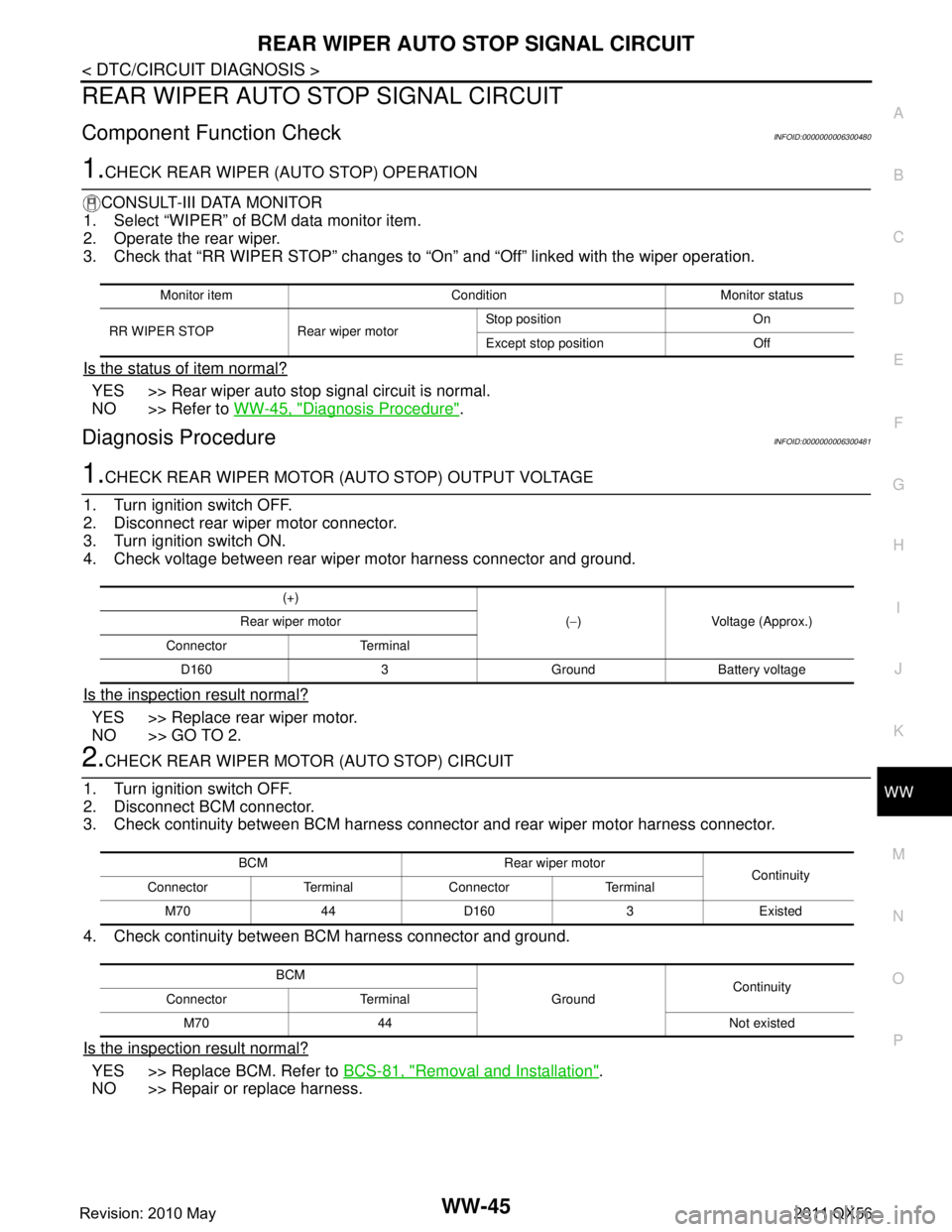
CONSULT-III DATA MONITOR
1. Select “WIPER” of BCM data monitor item.
2. Operate the rear wiper.
3. Check that “RR WIPER STOP” changes to “O n” and “Off” linked with the wiper operation.
Is the status of item normal?
YES >> Rear wiper auto stop signal circuit is normal.
NO >> Refer to WW-45, "
Diagnosis Procedure".
Diagnosis ProcedureINFOID:0000000006300481
1.CHECK REAR WIPER MOTOR (AUTO STOP) OUTPUT VOLTAGE
1. Turn ignition switch OFF.
2. Disconnect rear wiper motor connector.
3. Turn ignition switch ON.
4. Check voltage between rear wiper motor harness connector and ground.
Is the inspection result normal?
YES >> Replace rear wiper motor.
NO >> GO TO 2.
2.CHECK REAR WIPER MOTOR (AUTO STOP) CIRCUIT
1. Turn ignition switch OFF.
2. Disconnect BCM connector.
3. Check continuity between BCM harness connector and rear wiper motor harness connector.
4. Check continuity between BCM harness connector and ground.
Is the inspection result normal?
YES >> Replace BCM. Refer to BCS-81, "Removal and Installation".
NO >> Repair or replace harness.
Monitor item Condition Monitor status
RR WIPER STOP Rear wiper motor Stop position On
Except stop position Off
(+)
(− ) Voltage (Approx.)
Rear wiper motor
Connector Terminal D160 3 Ground Battery voltage
BCM Rear wiper motor Continuity
Connector Terminal Connector Terminal
M70 44 D160 3 Existed
BCM GroundContinuity
Connector Terminal
M70 44 Not existed
Revision: 2010 May2011 QX56