2011 INFINITI QX56 ground
[x] Cancel search: groundPage 5249 of 5598
![INFINITI QX56 2011 Factory Service Manual
SELECTOR LEVER POSITION INDICATORTM-161
< DTC/CIRCUIT DIAGNOSIS > [7AT: RE7R01B]
C
EF
G H
I
J
K L
M A
B
TM
N
O P
SELECTOR LEVER POSITION INDICATOR
Component Function CheckINFOID:0000000006226887
1.CH INFINITI QX56 2011 Factory Service Manual
SELECTOR LEVER POSITION INDICATORTM-161
< DTC/CIRCUIT DIAGNOSIS > [7AT: RE7R01B]
C
EF
G H
I
J
K L
M A
B
TM
N
O P
SELECTOR LEVER POSITION INDICATOR
Component Function CheckINFOID:0000000006226887
1.CH](/manual-img/42/57033/w960_57033-5248.png)
SELECTOR LEVER POSITION INDICATORTM-161
< DTC/CIRCUIT DIAGNOSIS > [7AT: RE7R01B]
C
EF
G H
I
J
K L
M A
B
TM
N
O P
SELECTOR LEVER POSITION INDICATOR
Component Function CheckINFOID:0000000006226887
1.CHECK SELECTOR LEVER POSI TION INDICATOR (PART 1)
1. Turn ignition switch ON.
2. Check that each position indicator lamp of the selector lever position indicator turns on when shifting the selector lever from “P” to “M” position.
Is the inspection result normal?
YES >> GO TO 2.
NO >> Go to TM-161, "
Diagnosis Procedure".
2.CHECK SELECTOR LEVER POSI TION INDICATOR (PART 2)
Check that the night illumination of the selector le ver position indicator turns on when setting the lighting
switch in 1st position.
Is the inspection result normal?
YES >> INSPECTION END
NO >> Go to TM-161, "
Diagnosis Procedure".
Diagnosis ProcedureINFOID:0000000006226888
1.CHECK MALFUNCTIONING ITEM
Which item is abnormal?
Position indicator lamp>> GO TO 2.
Illumination lamp>> GO TO 9.
2.CHECK POWER SOURCE (PART 1)
1. Turn ignition switch OFF.
2. Disconnect A/T shift selector connector.
3. Turn ignition switch ON.
4. Check voltage between A/T shift selector vehicle side harness connector terminal and ground.
Is the inspection result normal?
YES >> GO TO 3.
NO >> GO TO 6.
3.CHECK GROUND CIRCUIT
1. Turn ignition switch OFF.
2. Check continuity between A/T shift selector vehicle side harness connector terminal and ground.
Is the inspection result normal?
YES >> GO TO 4.
NO >> Repair or replace damaged parts.
4.CHECK SHIFT POSITION SWITCH (PART 1)
1. Disconnect shift position switch connector.
2. Check continuity between A/T shift selector connec tor terminals and shift position switch connector termi-
nals.
A/T shift selector vehicle side harness connector
GroundVoltage (Approx.)
Connector Terminal
M57 13 Battery voltage
A/T shift selector vehicle side harness connector GroundContinuity
Connector Terminal
M57 4 Existed
Revision: 2010 May2011 QX56
Page 5250 of 5598
![INFINITI QX56 2011 Factory Service Manual
TM-162
< DTC/CIRCUIT DIAGNOSIS >[7AT: RE7R01B]
SELECTOR LEVER POSITION INDICATOR
Is the inspection result normal?
YES >> GO TO 5.
NO >> Repair or replace damaged parts.
5.CHECK SELECTOR LEVER POSITIO INFINITI QX56 2011 Factory Service Manual
TM-162
< DTC/CIRCUIT DIAGNOSIS >[7AT: RE7R01B]
SELECTOR LEVER POSITION INDICATOR
Is the inspection result normal?
YES >> GO TO 5.
NO >> Repair or replace damaged parts.
5.CHECK SELECTOR LEVER POSITIO](/manual-img/42/57033/w960_57033-5249.png)
TM-162
< DTC/CIRCUIT DIAGNOSIS >[7AT: RE7R01B]
SELECTOR LEVER POSITION INDICATOR
Is the inspection result normal?
YES >> GO TO 5.
NO >> Repair or replace damaged parts.
5.CHECK SELECTOR LEVER POSITION INDICATOR
Check selector lever position indicator. Refer to TM-163, "
Component Inspection (Selector Lever Position Indi-
cator)".
Is the inspection result normal?
YES >> Check intermittent incident. Refer to GI-40, "Intermittent Incident".
NO >> Replace damaged parts.
6.CHECK HARNESS BETWEEN A/T SHIFT SELECTOR AND BCM (PART 1)
1. Turn ignition switch OFF.
2. Disconnect BCM connector.
3. Check continuity between A/T shift selector v ehicle side harness connector terminal and BCM vehicle
side harness connector terminal.
Is the inspection result normal?
YES >> GO TO 7.
NO >> Repair or replace damaged parts.
7.CHECK HARNESS BETWEEN A/T SHIFT SELECTOR AND BCM (PART 2)
Check continuity between A/T shift selector vehicle side harness connector terminal and ground.
Is the inspection result normal?
YES >> GO TO 8.
NO >> Repair or replace damaged parts.
8.CHECK BCM INPUT/OUTPUT SIGNAL
Check BCM input/output signal. Refer to BCS-33, "
Reference Value".
Is the inspection result normal?
A/T shift selector connector Shift position switch connector Condition Continuity
Connector Terminal Connector Terminal
M57 4
M281 10
Selector lever in “M”
position. Existed
1, 2, 3, 4, 5, 8, 9, 12 Not existed 12 Selector lever in “D”
position. Existed
1, 2, 3, 4, 5, 8, 9, 10 Not existed
13 1, 2
Selector lever in “P”
position. Existed
3, 4, 5, 8, 9, 10, 12 Not existed 1, 3 Selector lever in “R”
position. Existed
2, 4, 5, 8, 9, 10, 12 Not existed 1, 4 Selector lever in “D”
position. Existed
2, 3, 5, 8, 9, 10, 12 Not existed 1, 5 Selector lever in “N”
position. Existed
2, 3, 4, 8, 9, 10, 12 Not existed
A/T shift selector vehicle side harness connector BCM vehicle side harness connector Continuity
Connector Terminal Connector Terminal
M57 13 M71 104 Existed
A/T shift selector vehicle side harness connector GroundContinuity
Connector Terminal
M57 13 Not existed
Revision: 2010 May2011 QX56
Page 5405 of 5598

WCS
WCS-1
DRIVER INFORMATION & MULTIMEDIA
C
DE
F
G H
I
J
K L
M B
SECTION WCS
A
O P
CONTENTS
WARNING CHIME SYSTEM
PRECAUTION ................ ...............................3
PRECAUTIONS .............................................. .....3
Precaution for Supplemental Restraint System
(SRS) "AIR BAG" and "SEAT BELT PRE-TEN-
SIONER" ............................................................. ......
3
SYSTEM DESCRIPTION ..............................4
COMPONENT PARTS ................................... .....4
Component Parts Location .................................. ......4
Component Description .............................................4
Combination Meter ....................................................5
SYSTEM ..............................................................6
WARNING CHIME SYSTEM .......................................6
WARNING CHIME SYSTEM : System Diagram . ......6
WARNING CHIME SYSTEM : System Description
......
6
WARNING CHIME SYSTEM : Fail-Safe ...................7
LIGHT REMINDER WARNING CHIME ................. ......8
LIGHT REMINDER WARNING CHIME : System
Diagram .....................................................................
8
LIGHT REMINDER WARNING CHIME : System
Description ................................................................
8
FRONT FOG LIGHT REMINDER WARNING
CHIME .................................................................... ......
9
FRONT FOG LIGHT REMINDER WARNING
CHIME : System Diagram .......................................
10
FRONT FOG LIGHT REMINDER WARNING
CHIME : System Description ...................................
10
SEAT BELT WARNING CHIME ............................ ....10
SEAT BELT WARNING CHIME : System Diagram
....
11
SEAT BELT WARNING CHIME : System Descrip-
tion ...................................................................... ....
11
PARKING BRAKE RELEASE WARNING CHIME ....12
PARKING BRAKE RELEASE WARNING CHIME
: System Diagram ................................................ ....
12
PARKING BRAKE RELEASE WARNING CHIME
: System Description ................................................
12
DIAGNOSIS SYSTEM (COMBINATION
METER) .............................................................
14
CONSULT-III Function ............................................14
DIAGNOSIS SYSTEM (BCM) ...........................19
COMMON ITEM ..................................................... ....19
COMMON ITEM : CONSULT-III Function (BCM -
COMMON ITEM) .....................................................
19
BUZZER ................................................................. ....20
BUZZER : CONSULT-III Function (BCM - BUZZ-
ER) ..........................................................................
20
ECU DIAGNOSIS INFORMATION ..............22
COMBINATION METER ...................................22
Reference Value .................................................. ....22
Fail-Safe ..................................................................29
DTC Index ...............................................................30
BCM (BODY CONTROL MODULE) .................31
List of ECU Reference .............................................31
WIRING DIAGRAM ......................................32
WARNING CHIME SYSTEM .............................32
Wiring Diagram .................................................... ....32
BASIC INSPECTION ...................................37
DIAGNOSIS AND REPAIR WORKFLOW ........37
Work Flow ............................................................ ....37
DTC/CIRCUIT DIAGNOSIS .........................39
POWER SUPPLY AND GROUND CIRCUIT ....39
COMBINATION METER ........................................ ....39
Revision: 2010 May2011 QX56
Page 5430 of 5598

WCS-26
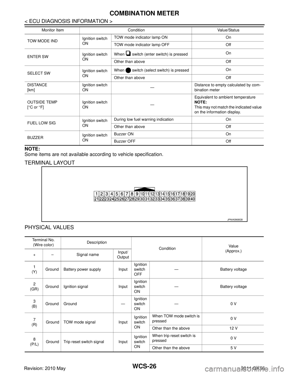
< ECU DIAGNOSIS INFORMATION >
COMBINATION METER
NOTE:
Some items are not available according to vehicle specification.
TERMINAL LAYOUT
PHYSICAL VALUES
TOW MODE INDIgnition switch
ONTOW mode indicator lamp ON On
TOW mode indicator lamp OFF Off
ENTER SW Ignition switch
ONWhen switch (enter switch) is pressed
On
Other than above Off
SELECT SW Ignition switch
ONWhen switch (select switch) is pressed
On
Other than above Off
DISTANCE
[km] Ignition switch
ON
—Distance to empty calculated by com-
bination meter
OUTSIDE TEMP
[ ° C or °F] Ignition switch
ON
—Equivalent to ambient temperature
NOTE:
This may not match the indicated value
on the information display.
FUEL LOW SIG Ignition switch
ONDuring low fuel warning indication On
Other than above Off
BUZZER Ignition switch
ONBuzzer ON On
Buzzer OFF Off
Monitor Item Condition Value/Status
JPNIA0968GB
Te r m i n a l N o .
(Wire color) Description
ConditionVa l u e
(Approx.)
+ – Signal name Input/
Output
1
(Y) Ground Battery power supply Input Ignition
switch
OFF— Battery voltage
2
(GR) Ground Ignition signal Input Ignition
switch
ON
— Battery voltage
3
(B) Ground Ground — Ignition
switch
ON—0 V
7
(R) Ground TOW mode signal Input Ignition
switch
ONWhen TOW mode switch is
pressed
0 V
Other than the above 12 V
8
(P/L) Ground Trip reset switch signal Input Ignition
switch
ONWhen trip reset switch is
pressed
0 V
Other than the above 5 V
Revision: 2010 May2011 QX56
Page 5431 of 5598

WCS
COMBINATION METERWCS-27
< ECU DIAGNOSIS INFORMATION >
C
DE
F
G H
I
J
K L
M B A
O P
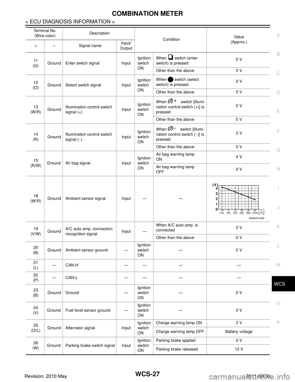
11
(G) Ground Enter switch signal Input Ignition
switch
ONWhen switch (enter
switch) is pressed
0 V
Other than the above 5 V
12
(O) Ground Select switch signal Input Ignition
switch
ONWhen switch (select
switch) is pressed
0 V
Other than the above 5 V
13
(W/R) Ground
Illumination control switch
signal (+) InputIgnition
switch
ON When switch [illumi-
nation control switch (+)] is
pressed
0 V
Other than the above 5 V
14
(R) Ground Illumination control switch
signal (
−) InputIgnition
switch
ON When switch [illumi-
nation control switch (
−)] is
pressed 0 V
Other than the above 5 V
15
(R/W) Ground Air bag signal Input Ignition
switch
ONAir bag warning lamp
ON
4 V
Air bag warning lamp
OFF 0 V
18
(W/R) Ground Ambient sensor signal Input — —
19
(V/W) Ground A/C auto amp. connection
recognition signal Input —When A/C auto amp. is
connected
5 V
Other than the above 0 V
20
(B) Ground Ambient sensor ground — Ignition
switch
ON—0 V
21
(L) —CAN-H — — — —
22
(P) —CAN-L — — — —
23
(B) Ground Ground — Ignition
switch
ON
—0 V
24
(V) Ground Fuel level sensor ground — Ignition
switch
ON—0 V
25
(O/L) Ground Alternator signal Input Ignition
switch
ONCharge warning lamp ON 2 V
Charge warning lamp OFF Battery voltage
26
(W) Ground Parking brake switch signal Input Ignition
switch
ONParking brake applied 0 V
Parking brake released 12 V
Te r m i n a l N o .
(Wire color) Description
ConditionVa l u e
(Approx.)
+ – Signal name Input/
Output
JSNIA0014GB
Revision: 2010 May2011 QX56
Page 5432 of 5598

WCS-28
< ECU DIAGNOSIS INFORMATION >
COMBINATION METER
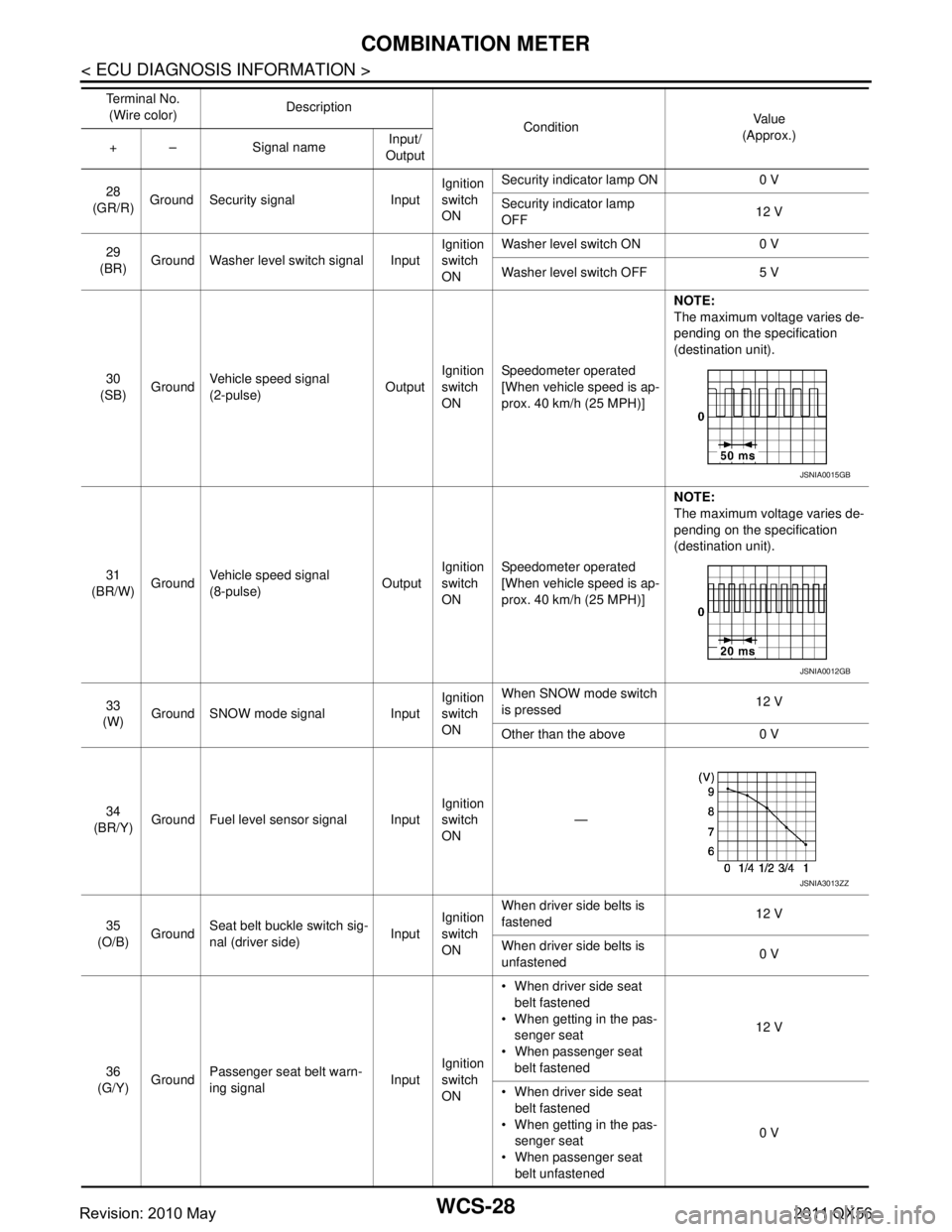
28
(GR/R) Ground Security signal Input Ignition
switch
ONSecurity indicator lamp ON 0 V
Security indicator lamp
OFF
12 V
29
(BR) Ground Washer level switch signal Input Ignition
switch
ONWasher level switch ON 0 V
Washer level switch OFF 5 V
30
(SB) Ground
Vehicle speed signal
(2-pulse) OutputIgnition
switch
ON Speedometer operated
[When vehicle speed is ap-
prox. 40 km/h (25 MPH)] NOTE:
The maximum voltage varies de-
pending on the specification
(destination unit).
31
(BR/W) GroundVehicle speed signal
(8-pulse)
OutputIgnition
switch
ONSpeedometer operated
[When vehicle speed is ap-
prox. 40 km/h (25 MPH)] NOTE:
The maximum voltage varies de-
pending on the specification
(destination unit).
33
(W) Ground SNOW mode signal Input Ignition
switch
ONWhen SNOW mode switch
is pressed
12 V
Other than the above 0 V
34
(BR/Y) Ground Fuel level sensor signal Input Ignition
switch
ON
—
35
(O/B) Ground Seat belt buckle switch sig-
nal (driver side)
InputIgnition
switch
ON When driver side belts is
fastened
12 V
When driver side belts is
unfastened 0 V
36
(G/Y) Ground Passenger seat belt warn-
ing signal
InputIgnition
switch
ON When driver side seat
belt fastened
When getting in the pas- senger seat
When passenger seat belt fastened 12 V
When driver side seat belt fastened
When getting in the pas- senger seat
When passenger seat belt unfastened 0 V
Te r m i n a l N o .
(Wire color) Description
ConditionVa l u e
(Approx.)
+ – Signal name Input/
Output
JSNIA0015GB
JSNIA0012GB
JSNIA3013ZZ
Revision: 2010 May2011 QX56
Page 5433 of 5598

WCS
COMBINATION METERWCS-29
< ECU DIAGNOSIS INFORMATION >
C
DE
F
G H
I
J
K L
M B A
O P
Fail-SafeINFOID:0000000006222689
FA I L - S A F E
The combination meter activates the fail-safe contro l if CAN communication with each unit is malfunctioning.
37
(R/Y) Ground Non-manual mode signal Input Ignition
switch
ONSelector manual mode po-
sition
12 V
Other than the above 0 V
38
(L/W) Ground Manual mode shift down
signal InputIgnition
switch
ON Selector lever DOWN oper-
ation
0 V
Other than the above 12 V
39
(Y/B) Ground Manual mode shift up sig-
nal InputIgnition
switch
ON Selector lever UP operation 0 V
Other than the above 12 V
40
(G/W) Ground Manual mode signal Input Ignition
switch
ONSelector manual mode po-
sition
0 V
Other than the above 12 V
Te r m i n a l N o .
(Wire color) Description
ConditionVa l u e
(Approx.)
+ – Signal name Input/
Output
Function Specifications
Speedometer
Reset to zero by suspending communication.
Tachometer
Engine coolant temperature gauge
Engine oil pressure gauge
Illumination control When suspending communication, changes to nighttime mode.
Information display Odo/trip meter An indicated value is maintained at communications blackout.
Shift position indicator The display turns OFF by suspending communication.
Door open warning The display turns OFF by suspending communication.
Buzzer The buzzer turns OFF by suspending communication.
Revision: 2010 May2011 QX56
Page 5443 of 5598

WCS
POWER SUPPLY AND GROUND CIRCUITWCS-39
< DTC/CIRCUIT DIAGNOSIS >
C
DE
F
G H
I
J
K L
M B A
O P
DTC/CIRCUIT DIAGNOSIS
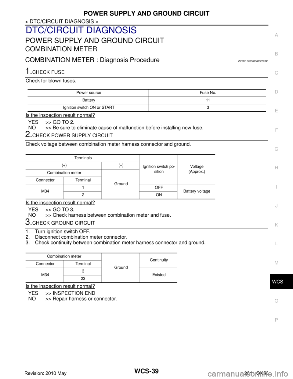
POWER SUPPLY AND GROUND CIRCUIT
COMBINATION METER
COMBINATION METER : Diagnosis ProcedureINFOID:0000000006222743
1.CHECK FUSE
Check for blown fuses.
Is the inspection result normal?
YES >> GO TO 2.
NO >> Be sure to eliminate cause of malfunction before installing new fuse.
2.CHECK POWER SUPPLY CIRCUIT
Check voltage between combination meter harness connector and ground.
Is the inspection result normal?
YES >> GO TO 3.
NO >> Check harness between combination meter and fuse.
3.CHECK GROUND CIRCUIT
1. Turn ignition switch OFF.
2. Disconnect combination meter connector.
3. Check continuity between combination meter harness connector and ground.
Is the inspection result normal?
YES >> INSPECTION END
NO >> Repair harness or connector.
Power source Fuse No.
Battery 11
Ignition switch ON or START 3
Te r m i n a l s
Ignition switch po-sition Vo l ta g e
(Approx.)
(+) (
−)
Combination meter
Ground
Connector Terminal
M34 1OFF
Battery voltage
2ON
Combination meter
GroundContinuity
Connector Terminal
M34 3
Existed
23
Revision: 2010 May2011 QX56