2011 INFINITI QX56 ground
[x] Cancel search: groundPage 5007 of 5598
ST-20
< DTC/CIRCUIT DIAGNOSIS >
HEATED STEERING WHEEL SWITCH INDICATOR LAMP
HEATED STEERING WHEEL SWITCH INDICATOR LAMP
Component Function CheckINFOID:0000000006225589
1.CHECK HEATED STEERING WHEEL INDICATOR LAMP
1. Turn ignition switch ON.
2. Turn heated steering wheel switch ON.
Does heated steering wheel indicator lamp turn on the lamp?
YES >> GO TO 2.
NO >> Go to ST-20, "
Diagnosis Procedure".
2.CHECK HEATED STEERING WHEEL INDICATOR LAMP
Turn heated steering wheel switch OFF.
Does heated steering wheel indicator lamp turn off the lamp?
YES >> INSPECTION END
NO >> Go to ST-20, "
Diagnosis Procedure".
Diagnosis ProcedureINFOID:0000000006225590
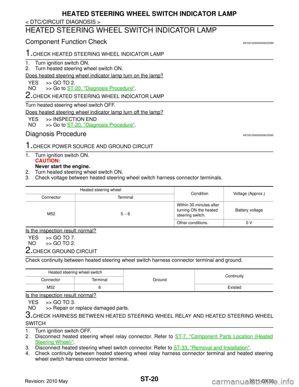
1.CHECK POWER SOURCE AND GROUND CIRCUIT
1. Turn ignition switch ON. CAUTION:
Never start the engine.
2. Turn heated steering wheel switch ON.
3. Check voltage between heated steering wheel switch harness connector terminals.
Is the inspection result normal?
YES >> GO TO 7.
NO >> GO TO 2.
2.CHECK GROUND CIRCUIT
Check continuity between heated steering wheel switch harness connector terminal and ground.
Is the inspection result normal?
YES >> GO TO 3.
NO >> Repair or replace damaged parts.
3.CHECK HARNESS BETWEEN HEATED STEERING WHEEL RELAY AND HEATED STEERING WHEEL
SWITCH
1. Turn ignition switch OFF.
2. Disconnect heated steering wheel relay connector. Refer to ST-7, "
Component Parts Location (Heated
Steering Wheel)".
3. Disconnect heated steering wheel switch connector. Refer to ST-33, "
Removal and Installation".
4. Check continuity between heated steering wheel relay harness connector terminal and heated steering
wheel switch harness connector terminal.
Heated steering wheel Condition Voltage (Approx.)
Connector Terminal
M52 5 − 6 Within 30 minutes after
turning ON the heated
steering switch.
Battery voltage
Other conditions. 0 V
Heated steering wheel switch GroundContinuity
Connector Terminal
M52 6 Existed
Revision: 2010 May2011 QX56
Page 5008 of 5598
HEATED STEERING WHEEL SWITCH INDICATOR LAMPST-21
< DTC/CIRCUIT DIAGNOSIS >
C
DE
F
H I
J
K L
M A
B
ST
N
O P
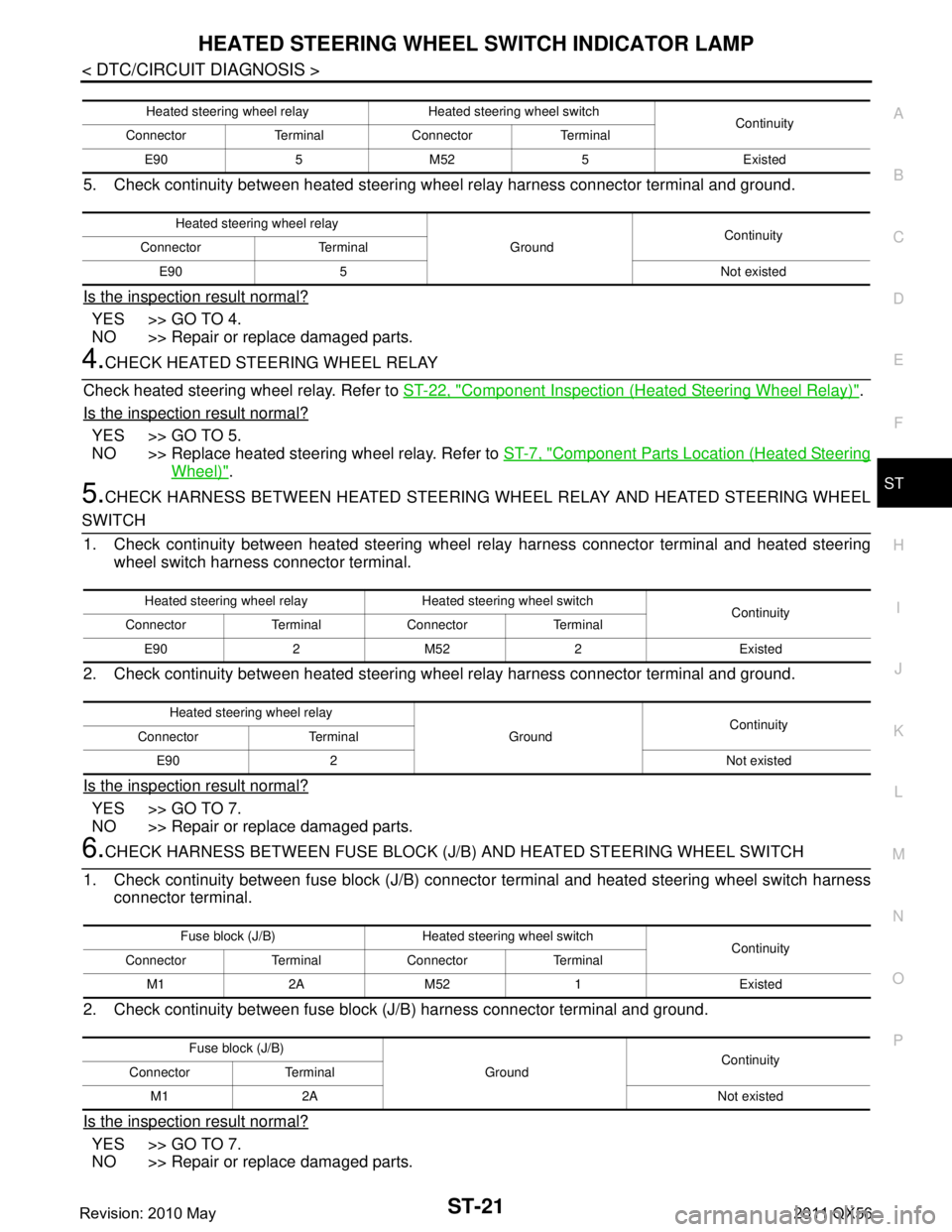
5. Check continuity between heated steering w heel relay harness connector terminal and ground.
Is the inspection result normal?
YES >> GO TO 4.
NO >> Repair or replace damaged parts.
4.CHECK HEATED STEERING WHEEL RELAY
Check heated steering wheel relay. Refer to ST-22, "
Component Inspection (Heated Steering Wheel Relay)".
Is the inspection result normal?
YES >> GO TO 5.
NO >> Replace heated steering wheel relay. Refer to ST-7, "
Component Parts Location (Heated Steering
Wheel)".
5.CHECK HARNESS BETWEEN HEATED STEERING WHEEL RELAY AND HEATED STEERING WHEEL
SWITCH
1. Check continuity between heated steering wheel relay harness connector terminal and heated steering
wheel switch harness connector terminal.
2. Check continuity between heated steering w heel relay harness connector terminal and ground.
Is the inspection result normal?
YES >> GO TO 7.
NO >> Repair or replace damaged parts.
6.CHECK HARNESS BETWEEN FUSE BLOCK (J/B) AND HEATED STEERING WHEEL SWITCH
1. Check continuity between fuse block (J/B) connec tor terminal and heated steering wheel switch harness
connector terminal.
2. Check continuity between fuse block (J/B) harness connector terminal and ground.
Is the inspection result normal?
YES >> GO TO 7.
NO >> Repair or replace damaged parts.
Heated steering wheel relay Heated steering wheel switch Continuity
Connector Terminal Connector Terminal
E90 5 M52 5 Existed
Heated steering wheel relay GroundContinuity
Connector Terminal
E90 5 Not existed
Heated steering wheel relay Heated steering wheel switch Continuity
Connector Terminal Connector Terminal
E90 2 M52 2 Existed
Heated steering wheel relay GroundContinuity
Connector Terminal
E90 2 Not existed
Fuse block (J/B) Heated steering wheel switch Continuity
Connector Terminal Connector Terminal
M1 2A M52 1 Existed
Fuse block (J/B) GroundContinuity
Connector Terminal
M1 2A Not existed
Revision: 2010 May2011 QX56
Page 5010 of 5598
HEATED STEERING WHEEL SYSTEM DOES NOT ACTIVATE
ST-23
< SYMPTOM DIAGNOSIS >
C
D E
F
H I
J
K L
M A
B
ST
N
O P
SYMPTOM DIAGNOSIS
HEATED STEERING WHEEL SYSTEM DOES NOT ACTIVATE
Description INFOID:0000000006225592
The heated steering wheel does not warm up.
The heated steering wheel system cannot be turned OFF.
Diagnosis ProcedureINFOID:0000000006225593
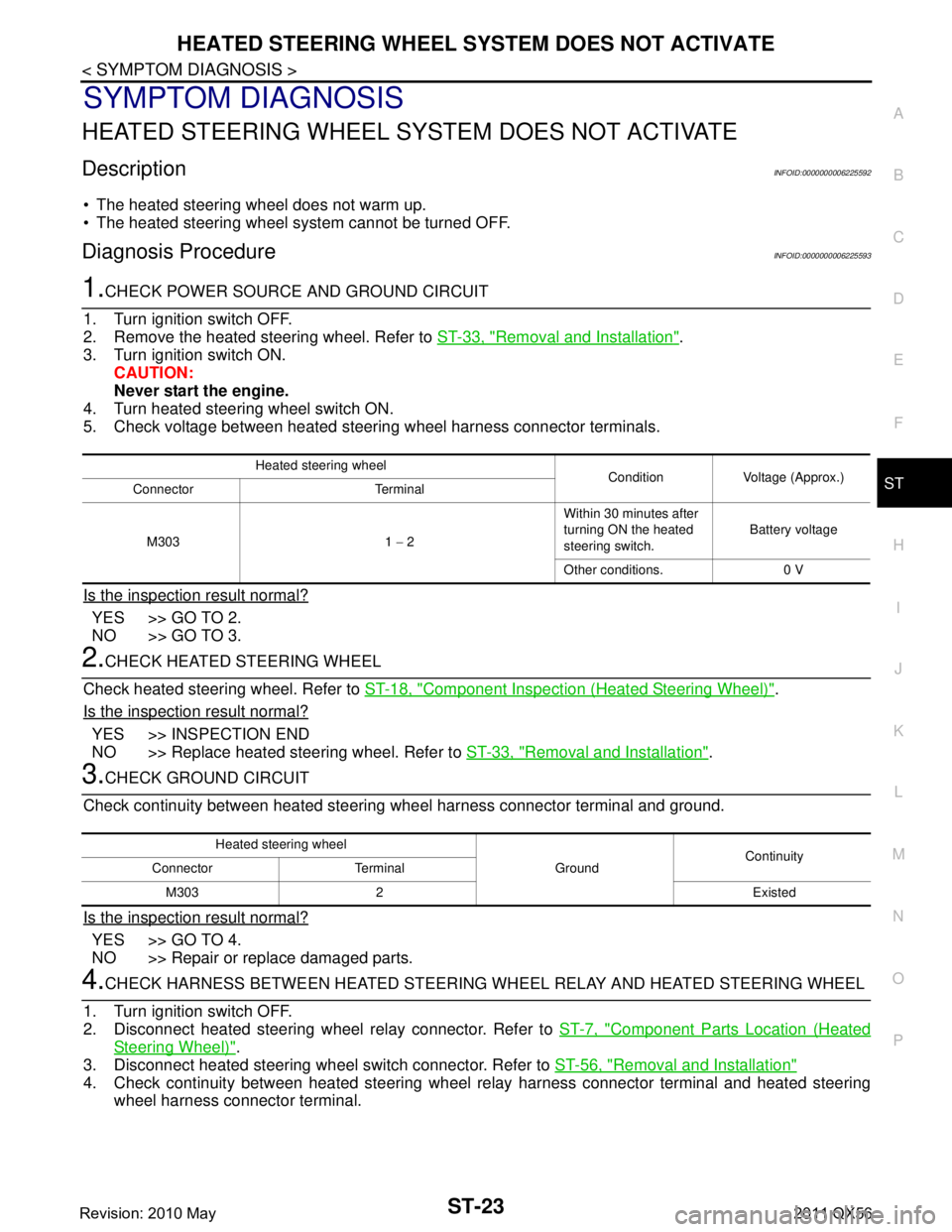
1.CHECK POWER SOURCE AND GROUND CIRCUIT
1. Turn ignition switch OFF.
2. Remove the heated steering wheel. Refer to ST-33, "
Removal and Installation".
3. Turn ignition switch ON.
CAUTION:
Never start the engine.
4. Turn heated steering wheel switch ON.
5. Check voltage between heated steering wheel harness connector terminals.
Is the inspection result normal?
YES >> GO TO 2.
NO >> GO TO 3.
2.CHECK HEATED STEERING WHEEL
Check heated steering wheel. Refer to ST-18, "
Component Inspection (Heated Steering Wheel)".
Is the inspection result normal?
YES >> INSPECTION END
NO >> Replace heated steering wheel. Refer to ST-33, "
Removal and Installation".
3.CHECK GROUND CIRCUIT
Check continuity between heated steering wheel harness connector terminal and ground.
Is the inspection result normal?
YES >> GO TO 4.
NO >> Repair or replace damaged parts.
4.CHECK HARNESS BETWEEN HEATED STEERING WHEEL RELAY AND HEATED STEERING WHEEL
1. Turn ignition switch OFF.
2. Disconnect heated steering wheel relay connector. Refer to ST-7, "
Component Parts Location (Heated
Steering Wheel)".
3. Disconnect heated steering wheel switch connector. Refer to ST-56, "
Removal and Installation"
4. Check continuity between heated steering wheel relay harness connector terminal and heated steering
wheel harness connector terminal.
Heated steering wheel Condition Voltage (Approx.)
Connector Terminal
M303 1 − 2 Within 30 minutes after
turning ON the heated
steering switch.
Battery voltage
Other conditions. 0 V
Heated steering wheel GroundContinuity
Connector Terminal
M303 2 Existed
Revision: 2010 May2011 QX56
Page 5011 of 5598
ST-24
< SYMPTOM DIAGNOSIS >
HEATED STEERING WHEEL SYSTEM DOES NOT ACTIVATE
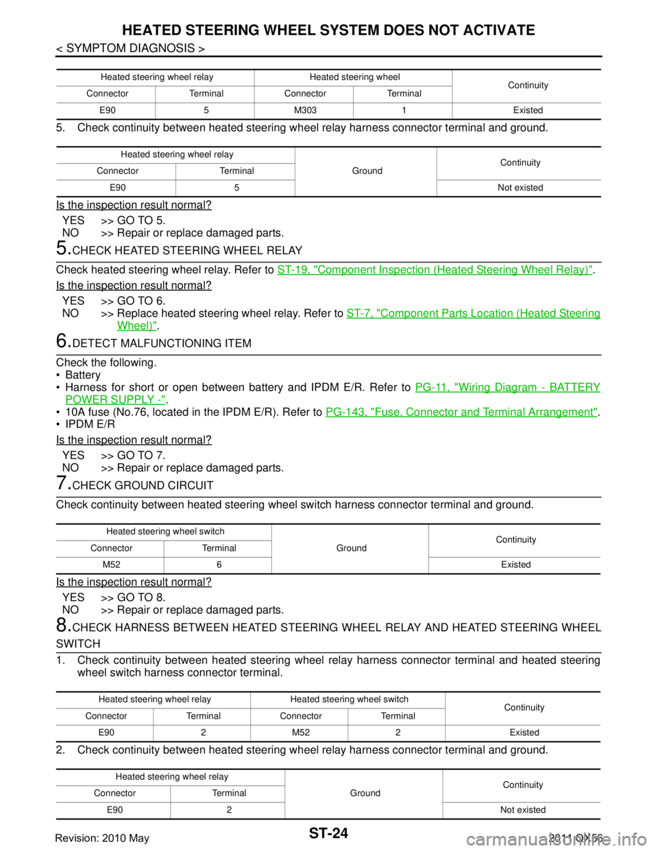
5. Check continuity between heated steering wheel relay harness connector terminal and ground.
Is the inspection result normal?
YES >> GO TO 5.
NO >> Repair or replace damaged parts.
5.CHECK HEATED STEERING WHEEL RELAY
Check heated steering wheel relay. Refer to ST-19, "
Component Inspection (Heated Steering Wheel Relay)".
Is the inspection result normal?
YES >> GO TO 6.
NO >> Replace heated steering wheel relay. Refer to ST-7, "
Component Parts Location (Heated Steering
Wheel)".
6.DETECT MALFUNCTIONING ITEM
Check the following.
Battery
Harness for short or open between bat tery and IPDM E/R. Refer to PG-11, "
Wiring Diagram - BATTERY
POWER SUPPLY -".
10A fuse (No.76, located in the IPDM E/R). Refer to PG-143, "
Fuse, Connector and Terminal Arrangement".
IPDM E/R
Is the inspection result normal?
YES >> GO TO 7.
NO >> Repair or replace damaged parts.
7.CHECK GROUND CIRCUIT
Check continuity between heated steering wheel switch harness connector terminal and ground.
Is the inspection result normal?
YES >> GO TO 8.
NO >> Repair or replace damaged parts.
8.CHECK HARNESS BETWEEN HEATED STEERING WHEEL RELAY AND HEATED STEERING WHEEL
SWITCH
1. Check continuity between heated steering wheel relay harness connector terminal and heated steering
wheel switch harness connector terminal.
2. Check continuity between heated steering w heel relay harness connector terminal and ground.
Heated steering wheel relay Heated steering wheel
Continuity
Connector Terminal Connector Terminal
E90 5 M303 1 Existed
Heated steering wheel relay GroundContinuity
Connector Terminal
E90 5 Not existed
Heated steering wheel switch GroundContinuity
Connector Terminal
M52 6 Existed
Heated steering wheel relay Heated steering wheel switch Continuity
Connector Terminal Connector Terminal
E90 2 M52 2 Existed
Heated steering wheel relay GroundContinuity
Connector Terminal
E90 2 Not existed
Revision: 2010 May2011 QX56
Page 5012 of 5598
HEATED STEERING WHEEL SYSTEM DOES NOT ACTIVATE
ST-25
< SYMPTOM DIAGNOSIS >
C
D E
F
H I
J
K L
M A
B
ST
N
O P
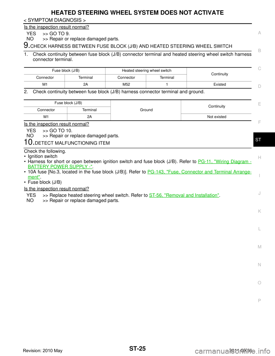
Is the inspection result normal?
YES >> GO TO 9.
NO >> Repair or replace damaged parts.
9.CHECK HARNESS BETWEEN FUSE BLOCK (J/B) AND HEATED STEERING WHEEL SWITCH
1. Check continuity between fuse block (J/B) connec tor terminal and heated steering wheel switch harness
connector terminal.
2. Check continuity between fuse block (J/B) harness connector terminal and ground.
Is the inspection result normal?
YES >> GO TO 10.
NO >> Repair or replace damaged parts.
10.DETECT MALFUNCTIONING ITEM
Check the following.
Ignition switch
Harness for short or open between ignition s witch and fuse block (J/B). Refer to PG-11, "
Wiring Diagram -
BATTERY POWER SUPPLY -".
10A fuse [No.3, located in the fuse block (J/B)]. Refer to PG-143, "
Fuse, Connector and Terminal Arrange-
ment".
Fuse block (J/B)
Is the inspection result normal?
YES >> Replace heated steering wheel switch. Refer to ST-56, "Removal and Installation".
NO >> Repair or replace damaged parts.
Fuse block (J/B) Heated steering wheel switch Continuity
Connector Terminal Connector Terminal
M1 2A M52 1 Existed
Fuse block (J/B) GroundContinuity
Connector Terminal
M1 2A Not existed
Revision: 2010 May2011 QX56
Page 5013 of 5598
ST-26
< SYMPTOM DIAGNOSIS >
HEATED STEERING WHEEL SWITCH INDICATOR LAMP DOES NOT TURN ON
HEATED STEERING WHEEL SWITCH INDICATOR LAMP DOES NOT
TURN ON
Description INFOID:0000000006225594
Heated steering wheel switch indicator lamp does not turn on the lamp.
Heated steering wheel switch indicator lamp does not turn off the lamp.
Diagnosis ProcedureINFOID:0000000006225595
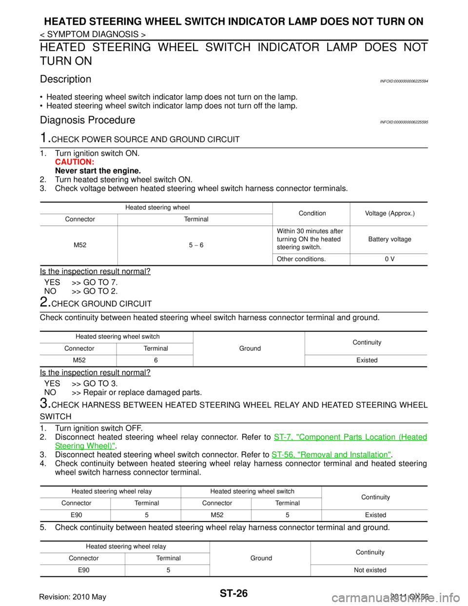
1.CHECK POWER SOURCE AND GROUND CIRCUIT
1. Turn ignition switch ON. CAUTION:
Never start the engine.
2. Turn heated steering wheel switch ON.
3. Check voltage between heated steering wheel switch harness connector terminals.
Is the inspection result normal?
YES >> GO TO 7.
NO >> GO TO 2.
2.CHECK GROUND CIRCUIT
Check continuity between heated steering wheel switch harness connector terminal and ground.
Is the inspection result normal?
YES >> GO TO 3.
NO >> Repair or replace damaged parts.
3.CHECK HARNESS BETWEEN HEATED STEERING WHEEL RELAY AND HEATED STEERING WHEEL
SWITCH
1. Turn ignition switch OFF.
2. Disconnect heated steering wheel relay connector. Refer to ST-7, "
Component Parts Location (Heated
Steering Wheel)".
3. Disconnect heated steering wheel switch connector. Refer to ST-56, "
Removal and Installation".
4. Check continuity between heated steering wheel relay harness connector terminal and heated steering
wheel switch harness connector terminal.
5. Check continuity between heated steering w heel relay harness connector terminal and ground.
Heated steering wheel
Condition Voltage (Approx.)
Connector Terminal
M52 5 − 6 Within 30 minutes after
turning ON the heated
steering switch.
Battery voltage
Other conditions. 0 V
Heated steering wheel switch GroundContinuity
Connector Terminal
M52 6 Existed
Heated steering wheel relay Heated steering wheel switch Continuity
Connector Terminal Connector Terminal
E90 5 M52 5 Existed
Heated steering wheel relay GroundContinuity
Connector Terminal
E90 5 Not existed
Revision: 2010 May2011 QX56
Page 5014 of 5598
HEATED STEERING WHEEL SWITCH INDICATOR LAMP DOES NOT TURN ON
ST-27
< SYMPTOM DIAGNOSIS >
C
D E
F
H I
J
K L
M A
B
ST
N
O P
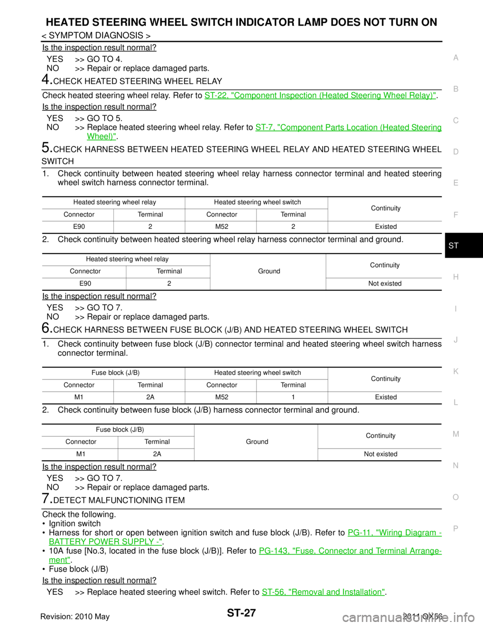
Is the inspection result normal?
YES >> GO TO 4.
NO >> Repair or replace damaged parts.
4.CHECK HEATED STEERING WHEEL RELAY
Check heated steering wheel relay. Refer to ST-22, "
Component Inspection (Heated Steering Wheel Relay)".
Is the inspection result normal?
YES >> GO TO 5.
NO >> Replace heated steering wheel relay. Refer to ST-7, "
Component Parts Location (Heated Steering
Wheel)".
5.CHECK HARNESS BETWEEN HEATED STEERING WHEEL RELAY AND HEATED STEERING WHEEL
SWITCH
1. Check continuity between heated steering wheel relay harness connector terminal and heated steering
wheel switch harness connector terminal.
2. Check continuity between heated steering w heel relay harness connector terminal and ground.
Is the inspection result normal?
YES >> GO TO 7.
NO >> Repair or replace damaged parts.
6.CHECK HARNESS BETWEEN FUSE BLOCK (J/B) AND HEATED STEERING WHEEL SWITCH
1. Check continuity between fuse block (J/B) connec tor terminal and heated steering wheel switch harness
connector terminal.
2. Check continuity between fuse block (J/B) harness connector terminal and ground.
Is the inspection result normal?
YES >> GO TO 7.
NO >> Repair or replace damaged parts.
7.DETECT MALFUNCTIONING ITEM
Check the following.
Ignition switch
Harness for short or open between ignition s witch and fuse block (J/B). Refer to PG-11, "
Wiring Diagram -
BATTERY POWER SUPPLY -".
10A fuse [No.3, located in the fuse block (J/B)]. Refer to PG-143, "
Fuse, Connector and Terminal Arrange-
ment".
Fuse block (J/B)
Is the inspection result normal?
YES >> Replace heated steering wheel switch. Refer to ST-56, "Removal and Installation".
Heated steering wheel relay Heated steering wheel switch
Continuity
Connector Terminal Connector Terminal
E90 2 M52 2 Existed
Heated steering wheel relay GroundContinuity
Connector Terminal
E90 2 Not existed
Fuse block (J/B) Heated steering wheel switch Continuity
Connector Terminal Connector Terminal
M1 2A M52 1 Existed
Fuse block (J/B) GroundContinuity
Connector Terminal
M1 2A Not existed
Revision: 2010 May2011 QX56
Page 5034 of 5598
STEERING GEAR AND LINKAGEST-47
< REMOVAL AND INSTALLATION >
C
DE
F
H I
J
K L
M A
B
ST
N
O P
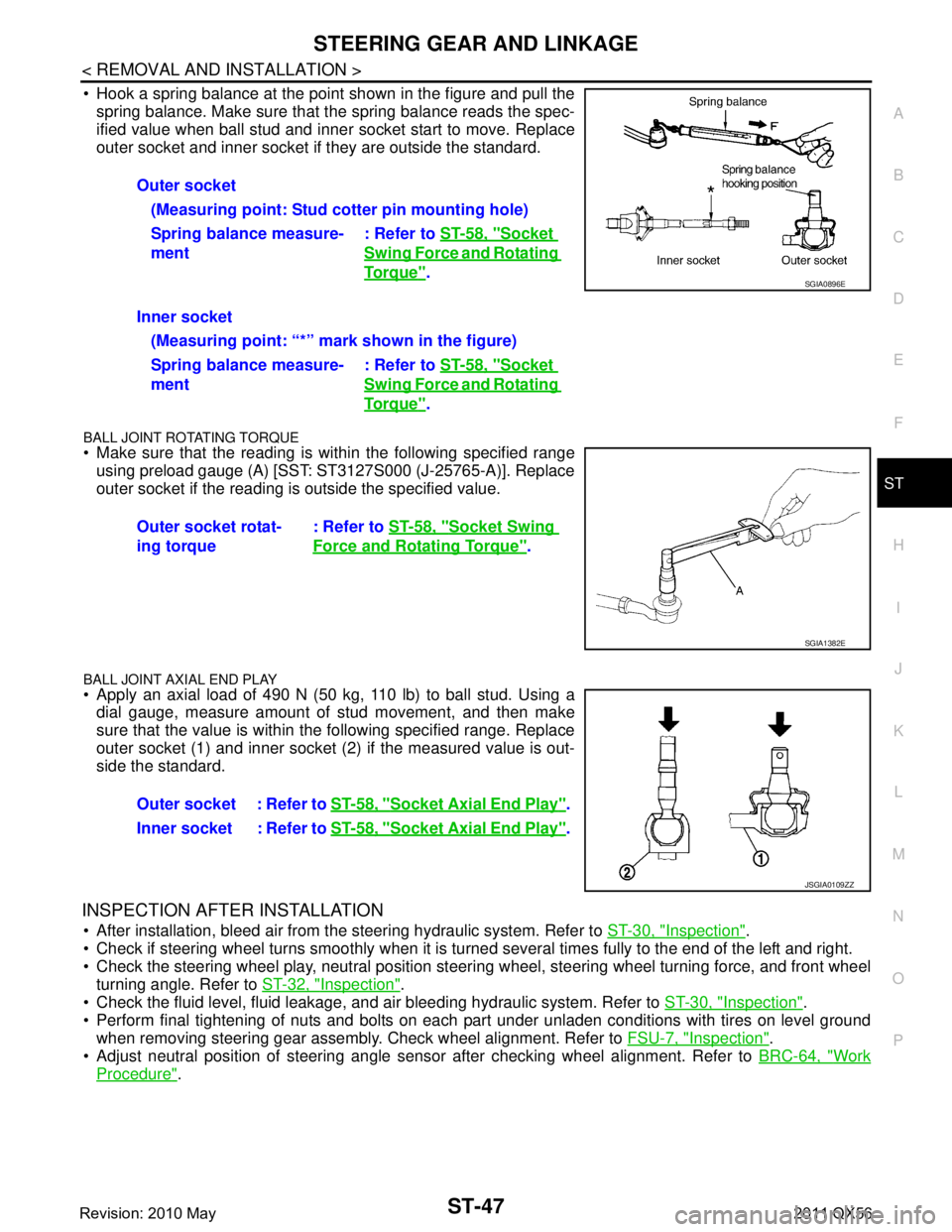
Hook a spring balance at the point shown in the figure and pull the spring balance. Make sure that the spring balance reads the spec-
ified value when ball stud and inner socket start to move. Replace
outer socket and inner socket if they are outside the standard.
BALL JOINT ROTATING TORQUE
Make sure that the reading is within the following specified rangeusing preload gauge (A) [SST: ST3127S000 (J-25765-A)]. Replace
outer socket if the reading is outside the specified value.
BALL JOINT AXIAL END PLAY
Apply an axial load of 490 N (50 kg, 110 lb) to ball stud. Using adial gauge, measure amount of stud movement, and then make
sure that the value is within the following specified range. Replace
outer socket (1) and inner socket (2) if the measured value is out-
side the standard.
INSPECTION AFTER INSTALLATION
After installation, bleed air from the steering hydraulic system. Refer to ST-30, "Inspection".
Check if steering wheel turns smoothly when it is turned several times fully to the end of the left and right.
Check the steering wheel play, neutral position steeri ng wheel, steering wheel turning force, and front wheel
turning angle. Refer to ST-32, "
Inspection".
Check the fluid level, fluid leakage, and air bleeding hydraulic system. Refer to ST-30, "
Inspection".
Perform final tightening of nuts and bolts on each part under unladen conditions with tires on level ground when removing steering gear assembly. Check wheel alignment. Refer to FSU-7, "
Inspection".
Adjust neutral position of steering angle sensor after checking wheel alignment. Refer to BRC-64, "
Work
Procedure".
Outer socket
(Measuring point: Stud cotter pin mounting hole)
Spring balance measure-
ment : Refer to
ST-58, "
Socket
Swing Force and Rotating
To r q u e".
Inner socket (Measuring point: “*” mark shown in the figure)
Spring balance measure-
ment : Refer to
ST-58, "
Socket
Swing Force and Rotating
To r q u e".
Outer socket rotat-
ing torque : Refer to
ST-58, "
Socket Swing
Force and Rotating Torque".
SGIA0896E
SGIA1382E
Outer socket : Refer to ST-58, "Socket Axial End Play".
Inner socket : Refer to ST-58, "
Socket Axial End Play".
JSGIA0109ZZ
Revision: 2010 May2011 QX56