2011 INFINITI QX56 ground
[x] Cancel search: groundPage 5065 of 5598

STC-20
< DTC/CIRCUIT DIAGNOSIS >
VEHICLE SPEED SIGNAL CIRCUIT
VEHICLE SPEED SIGNAL CIRCUIT
Diagnosis ProcedureINFOID:0000000006256130
1.PERFORM COMBINATION METER SELF-DIAGNOSIS
With CONSULT-III
Perform “METER/M&A” self-diagnosis. Refer to MWI-30, "
CONSULT-III Function".
Is any DTC detected?
YES >> Check the DTC.
NO >> GO TO 2.
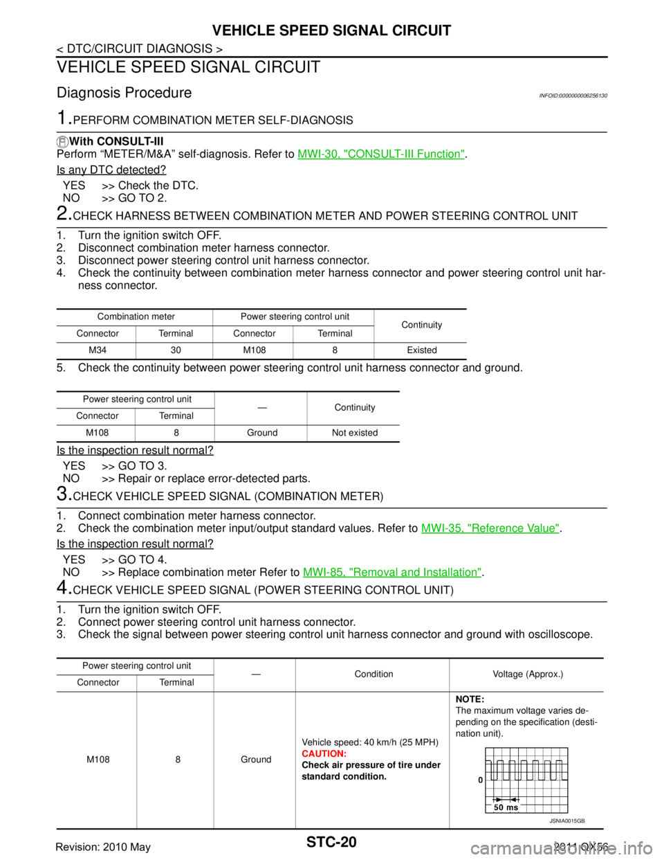
2.CHECK HARNESS BETWEEN COMBINATION ME TER AND POWER STEERING CONTROL UNIT
1. Turn the ignition switch OFF.
2. Disconnect combination meter harness connector.
3. Disconnect power steering control unit harness connector.
4. Check the continuity between combination meter harness connector and power steering control unit har-
ness connector.
5. Check the continuity between power st eering control unit harness connector and ground.
Is the inspection result normal?
YES >> GO TO 3.
NO >> Repair or replace error-detected parts.
3.CHECK VEHICLE SPEED SIGN AL (COMBINATION METER)
1. Connect combination meter harness connector.
2. Check the combination meter input/output standard values. Refer to MWI-35, "
Reference Value".
Is the inspection result normal?
YES >> GO TO 4.
NO >> Replace combination meter Refer to MWI-85, "
Removal and Installation".
4.CHECK VEHICLE SPEED SIGNAL (POWER STEERING CONTROL UNIT)
1. Turn the ignition switch OFF.
2. Connect power steering control unit harness connector.
3. Check the signal between power steering cont rol unit harness connector and ground with oscilloscope.
Combination meter Power steering control unit
Continuity
Connector Terminal Connector Terminal
M34 30 M108 8 Existed
Power steering control unit —Continuity
Connector Terminal
M108 8 Ground Not existed
Power steering control unit — Condition Voltage (Approx.)
Connector Terminal
M108 8 Ground Vehicle speed: 40 km/h (25 MPH)
CAUTION:
Check air pressure of tire under
standard condition.NOTE:
The maximum voltage varies de-
pending on the specification (desti-
nation unit).
JSNIA0015GB
Revision: 2010 May2011 QX56
Page 5067 of 5598

STC-22
< SYMPTOM DIAGNOSIS >
UNBALANCE STEERING WHEEL TURNING FORCE (TORQUE VARIATION)
SYMPTOM DIAGNOSIS
UNBALANCE STEERING WHEEL TURNING FORCE (TORQUE VARIA-
TION)
Description INFOID:0000000006256131
Hard steering when fully turning the steering wheel.
Light steering when driving at a high speed.
Diagnosis Procedure INFOID:0000000006256132
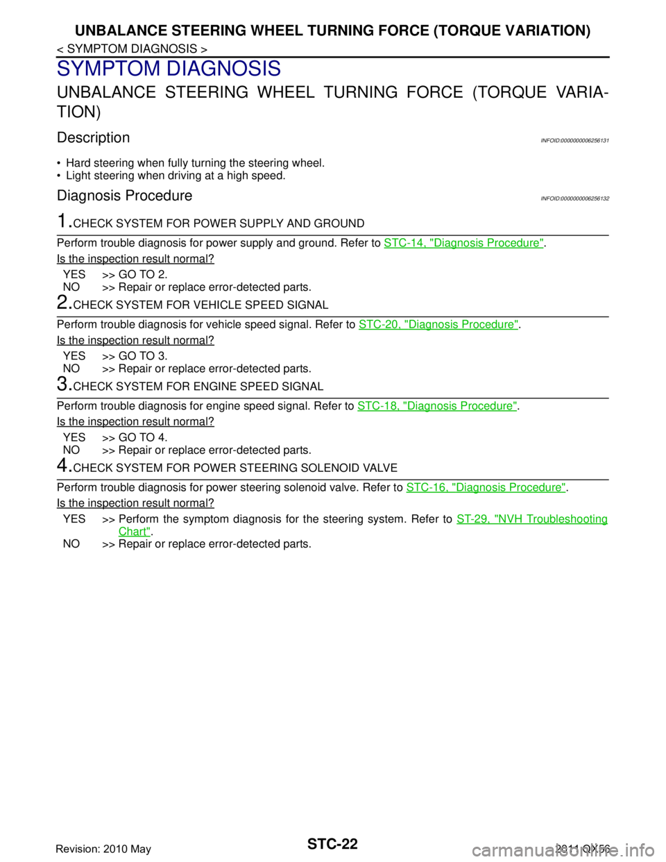
1.CHECK SYSTEM FOR POWER SUPPLY AND GROUND
Perform trouble diagnosis for power supply and ground. Refer to STC-14, "
Diagnosis Procedure".
Is the inspection result normal?
YES >> GO TO 2.
NO >> Repair or replace error-detected parts.
2.CHECK SYSTEM FOR VEHICLE SPEED SIGNAL
Perform trouble diagnosis for vehicle speed signal. Refer to STC-20, "
Diagnosis Procedure".
Is the inspection result normal?
YES >> GO TO 3.
NO >> Repair or replace error-detected parts.
3.CHECK SYSTEM FOR ENGINE SPEED SIGNAL
Perform trouble diagnosis for engine speed signal. Refer to STC-18, "
Diagnosis Procedure".
Is the inspection result normal?
YES >> GO TO 4.
NO >> Repair or replace error-detected parts.
4.CHECK SYSTEM FOR POWER STEERING SOLENOID VALVE
Perform trouble diagnosis for power steering solenoid valve. Refer to STC-16, "
Diagnosis Procedure".
Is the inspection result normal?
YES >> Perform the symptom diagnosis for the steering system. Refer to ST-29, "NVH Troubleshooting
Chart".
NO >> Repair or replace error-detected parts.
Revision: 2010 May2011 QX56
Page 5082 of 5598

STR-14
< DTC/CIRCUIT DIAGNOSIS >
B TERMINAL CIRCUIT
DTC/CIRCUIT DIAGNOSIS
B TERMINAL CIRCUIT
Diagnosis ProcedureINFOID:0000000006275524
CAUTION:
Perform diagnosis under the condition that engine cannot start by the following procedure.
1. Remove fuel pump fuse.
2. Crank or start the engine (where possi ble) until the fuel pressure is released.
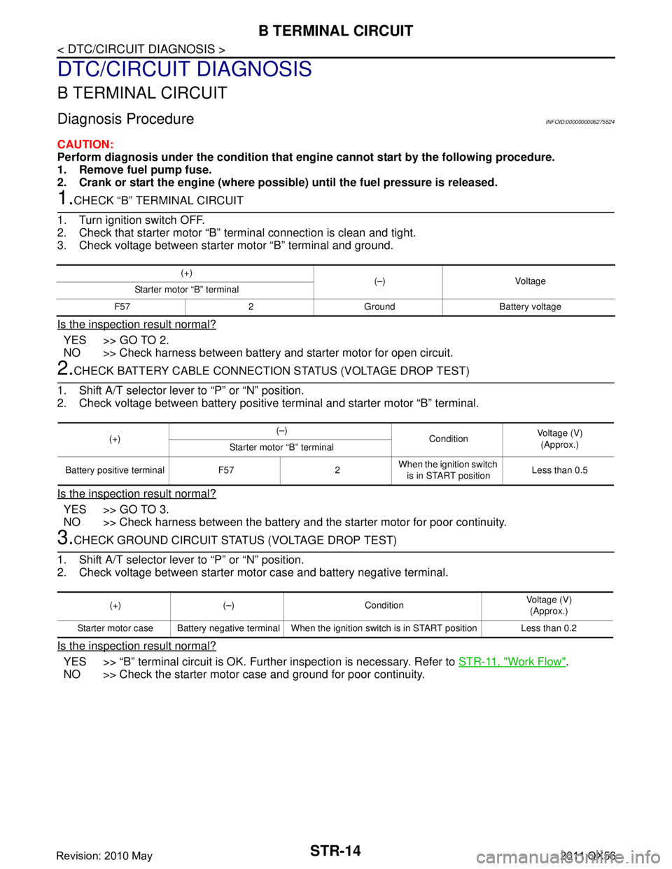
1.CHECK “B” TERMINAL CIRCUIT
1. Turn ignition switch OFF.
2. Check that starter motor “B” terminal connection is clean and tight.
3. Check voltage between starter motor “B” terminal and ground.
Is the inspection result normal?
YES >> GO TO 2.
NO >> Check harness between battery and starter motor for open circuit.
2.CHECK BATTERY CABLE CONNECTION STATUS (VOLTAGE DROP TEST)
1. Shift A/T selector lever to “P” or “N” position.
2. Check voltage between battery positive terminal and starter motor “B” terminal.
Is the inspection result normal?
YES >> GO TO 3.
NO >> Check harness between the battery and the starter motor for poor continuity.
3.CHECK GROUND CIRCUIT STATUS (VOLTAGE DROP TEST)
1. Shift A/T selector lever to “P” or “N” position.
2. Check voltage between starter motor case and battery negative terminal.
Is the inspection result normal?
YES >> “B” terminal circuit is OK. Further inspection is necessary. Refer to STR-11, "Work Flow".
NO >> Check the starter motor case and ground for poor continuity.
(+) (–) Voltage
Starter motor “B” terminal
F57 2 Ground Battery voltage
(+) (–)
ConditionVoltage (V)
(Approx.)
Starter motor “B” terminal
Battery positive terminal F57 2 When the ignition switch
is in START position Less than 0.5
(+) (–) Condition Voltage (V)
(Approx.)
Starter motor case Battery negative terminal When the ignition switch is in START position Less than 0.2
Revision: 2010 May2011 QX56
Page 5083 of 5598

S CONNECTOR CIRCUITSTR-15
< DTC/CIRCUIT DIAGNOSIS >
C
DE
F
G H
I
J
K L
M A
STR
NP
O
S CONNECTOR CIRCUIT
Diagnosis ProcedureINFOID:0000000006275525
CAUTION:
Perform diagnosis under the cond
ition that engine cannot start by the following procedure.
1. Remove fuel pump fuse.
2. Crank or start the engine (where possi ble) until the fuel pressure is released.
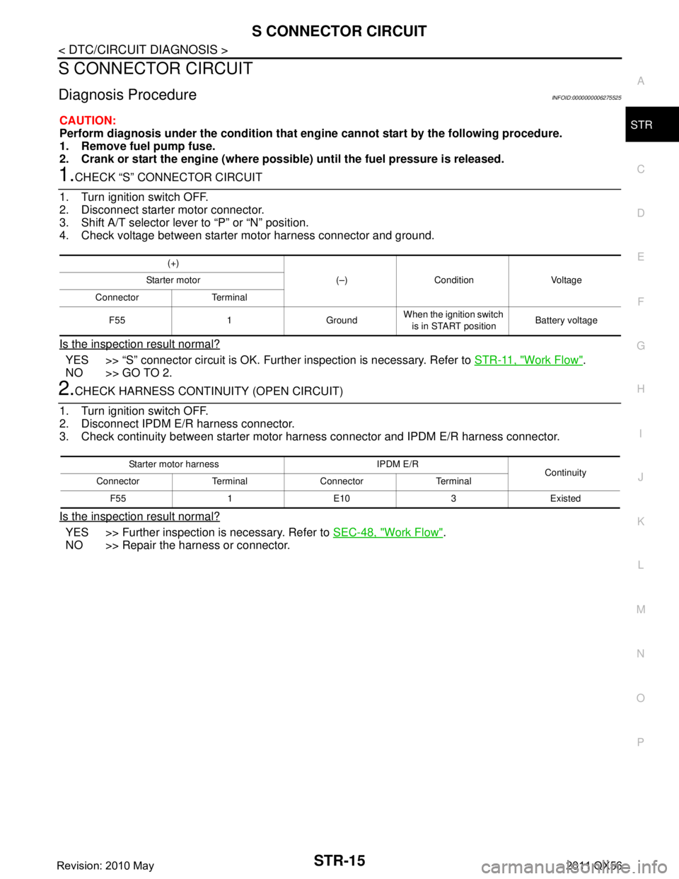
1.CHECK “S” CONNECTOR CIRCUIT
1. Turn ignition switch OFF.
2. Disconnect starter motor connector.
3. Shift A/T selector lever to “P” or “N” position.
4. Check voltage between starter motor harness connector and ground.
Is the inspection result normal?
YES >> “S” connector circuit is OK. Furt her inspection is necessary. Refer to STR-11, "Work Flow".
NO >> GO TO 2.
2.CHECK HARNESS CONTI NUITY (OPEN CIRCUIT)
1. Turn ignition switch OFF.
2. Disconnect IPDM E/R harness connector.
3. Check continuity between starter motor harness connector and IPDM E/R harness connector.
Is the inspection result normal?
YES >> Further inspection is necessary. Refer to SEC-48, "Work Flow".
NO >> Repair the harness or connector.
(+)
(–) Condition Voltage
Starter motor
Connector Terminal
F55 1 Ground When the ignition switch
is in START position Battery voltage
Starter motor harness IPDM E/R
Continuity
Connector Terminal Connector Terminal
F55 1 E10 3 Existed
Revision: 2010 May2011 QX56
Page 5091 of 5598

TM-3
CEF
G H
I
J
K L
M A
B
TM
N
O P
Description ..........................................................
..
114
DTC Logic .............................................................114
Diagnosis Procedure .............................................115
P0730 INCORRECT GEAR RATIO ..................116
Description .......................................................... ..116
DTC Logic .............................................................116
Diagnosis Procedure .............................................116
P0731 1GR INCORRECT RATIO .....................118
Description .......................................................... ..118
DTC Logic .............................................................118
Diagnosis Procedure .............................................119
P0732 2GR INCORRECT RATIO .....................120
Description .......................................................... ..120
DTC Logic .............................................................120
Diagnosis Procedure .............................................121
P0733 3GR INCORRECT RATIO .....................122
Description .......................................................... ..122
DTC Logic .............................................................122
Diagnosis Procedure .............................................123
P0734 4GR INCORRECT RATIO .....................124
Description .......................................................... ..124
DTC Logic .............................................................124
Diagnosis Procedure .............................................125
P0735 5GR INCORRECT RATIO .....................126
Description .......................................................... ..126
DTC Logic .............................................................126
Diagnosis Procedure .............................................127
P0740 TORQUE CONVERTER ........................128
DTC Logic ........................................................... ..128
Diagnosis Procedure .............................................128
P0744 TORQUE CONVERTER ........................129
Description .......................................................... ..129
DTC Logic .............................................................129
Diagnosis Procedure .............................................129
P0745 PRESSURE CONTROL SOLENOID A ..131
DTC Logic ........................................................... ..131
Diagnosis Procedure .............................................131
P0750 SHIFT SOLENOID A .............................132
DTC Logic ........................................................... ..132
Diagnosis Procedure .............................................132
P0775 PRESSURE CONTROL SOLENOID B ..133
DTC Logic ........................................................... ..133
Diagnosis Procedure .............................................133
P0780 SHIFT ....................................................134
Description .......................................................... ..134
DTC Logic .............................................................134
Diagnosis Procedure .............................................134
P0795 PRESSURE CONTROL SOLENOID C ..136
DTC Logic ........................................................... ..136
Diagnosis Procedure ........................................... ..136
P1705 TP SENSOR .........................................137
DTC Logic ..............................................................137
Diagnosis Procedure .............................................137
P1721 VEHICLE SPEED SIGNAL ..................138
Description .............................................................138
DTC Logic ..............................................................138
Diagnosis Procedure .............................................139
P1730 INTERLOCK ........................................140
Description .............................................................140
DTC Logic ..............................................................140
Judgment of Interlock ............................................140
Diagnosis Procedure .............................................141
P1734 7GR INCORRECT RATIO ...................142
Description .............................................................142
DTC Logic ..............................................................142
Diagnosis Procedure .............................................143
P1815 M-MODE SWITCH ...............................144
DTC Logic ..............................................................144
Diagnosis Procedure .............................................144
Component Inspection (Manual Mode Switch) ......146
P2713 PRESSURE CONTROL SOLENOID D .147
DTC Logic ............................................................ ..147
Diagnosis Procedure .............................................147
P2722 PRESSURE CONTROL SOLENOID E .148
DTC Logic ..............................................................148
Diagnosis Procedure .............................................148
P2731 PRESSURE CONTROL SOLENOID F .149
DTC Logic ..............................................................149
Diagnosis Procedure .............................................149
P2807 PRESSURE CONTROL SOLENOID G .150
DTC Logic ............................................................ ..150
Diagnosis Procedure .............................................150
MAIN POWER SUPPLY AND GROUND CIR-
CUIT ................................................................
151
Diagnosis Procedure .............................................151
TOW MODE SYSTEM .....................................153
Component Function Check ..................................153
Diagnosis Procedure .............................................153
Component Inspection ...........................................155
SHIFT POSITION INDICATOR CIRCUIT ........156
Description .............................................................156
Component Function Check ..................................156
Diagnosis Procedure .............................................156
SHIFT LOCK SYSTEM ...................................157
Component Function Check ..................................157
Diagnosis Procedure .............................................157
Component Inspection (Stop Lamp Switch) ..........159
Component Inspection (Park Position Switch) ......159
Revision: 2010 May2011 QX56
Page 5161 of 5598
![INFINITI QX56 2011 Factory Service Manual
TCM
TM-73
< ECU DIAGNOSIS INFORMATION > [7AT: RE7R01B]
C
EF
G H
I
J
K L
M A
B
TM
N
O P
*: Not mounted but always display as OFF.
TERMINAL LAYOUT
PHYSICAL VALUES
SLCT LVR POSI Selector lever in “N
� INFINITI QX56 2011 Factory Service Manual
TCM
TM-73
< ECU DIAGNOSIS INFORMATION > [7AT: RE7R01B]
C
EF
G H
I
J
K L
M A
B
TM
N
O P
*: Not mounted but always display as OFF.
TERMINAL LAYOUT
PHYSICAL VALUES
SLCT LVR POSI Selector lever in “N
�](/manual-img/42/57033/w960_57033-5160.png)
TCM
TM-73
< ECU DIAGNOSIS INFORMATION > [7AT: RE7R01B]
C
EF
G H
I
J
K L
M A
B
TM
N
O P
*: Not mounted but always display as OFF.
TERMINAL LAYOUT
PHYSICAL VALUES
SLCT LVR POSI Selector lever in “N
” and “P” positions N/P
Selector lever in “R” position R
Selector lever in “D” and “DS” positions D
Selector lever in “M” position: 7GR
Selector lever in “M” position: 6GR 6
Selector lever in “M” position: 5GR 5
Selector lever in “M” position: 4GR 4
Selector lever in “M” position: 3GR 3
Selector lever in “M” position: 2GR 2
Selector lever in “M” position: 1GR 1
GEAR During driving 1st, 2nd, 3rd, 4th, 5th, 6th, 7th
NEXT GR POSI During driving 1st, 2nd, 3rd, 4th, 5th, 6th, 7th
SHIFT MODE Driving with the D position 0 or 3
Driving with the manual mode 4 or 8
D/C PARTS At 1GR - 2GR shift control FAIL
Other than the above NOTFAIL
FR/B PARTS At control fixed to 1GR FAIL
Other than the above NOTFAIL
2346/B PARTS At control fixed to 1GR FAIL
Other than the above NOTFAIL
2346B/DC PARTS At 2GR - 3GR - 4GR
shift control FAIL
Other than the above NOTFAIL
N IDLE STATUS Idle neutral is active ON
Other than the above OFF
Item name Condition Value / Status (Approx.)
SCIA1658E
Te r m i n a l
(Wire color) Description
Condition Value (Approx.)
+ −Signal name Input/
Output
1
(V) Ground Power supply Input Ignition switch ON Battery voltage
Ignition switch OFF 0 V
2
(P) Ground Power supply
(Memory back-up) Input Always Battery voltage
Revision: 2010 May2011 QX56
Page 5162 of 5598
![INFINITI QX56 2011 Factory Service Manual
TM-74
< ECU DIAGNOSIS INFORMATION >[7AT: RE7R01B]
TCM
Fail-Safe
INFOID:0000000006226783
TCM has the electrical fail-safe mode. The mode is divi ded into a maximum of 3 phases (1st fail-safe, 2nd fail INFINITI QX56 2011 Factory Service Manual
TM-74
< ECU DIAGNOSIS INFORMATION >[7AT: RE7R01B]
TCM
Fail-Safe
INFOID:0000000006226783
TCM has the electrical fail-safe mode. The mode is divi ded into a maximum of 3 phases (1st fail-safe, 2nd fail](/manual-img/42/57033/w960_57033-5161.png)
TM-74
< ECU DIAGNOSIS INFORMATION >[7AT: RE7R01B]
TCM
Fail-Safe
INFOID:0000000006226783
TCM has the electrical fail-safe mode. The mode is divi ded into a maximum of 3 phases (1st fail-safe, 2nd fail-
safe and final fail-safe) and functions so that the operat ion can be continued even if the signal circuit of the
main electronically controll ed input/output parts is damaged.
Even if the electronic circuit is normal, the fail-safe mode may start under special conditions (such as when the
brake pedal is depressed suddenly from a hard wheel spin status to stop the rotation of wheels). In this case,
turn the ignition switch OFF and back to ON after 5 seconds to resume the normal shift pattern.
Consequently, the customer's vehicle may already return to the normal condition. Refer to TM-88, "
Diagnosis
Flow".
FAIL-SAFE FUNCTION
3
(L) —CAN-H
Input/
Output ——
4
(SB) —K-line Input/
Output ——
5
(B) Ground Ground Output Always 0 V
6
(V) Ground Power supply Input Ignition switch ON Battery voltage
Ignition switch OFF 0 V
7
(R) Ground Back-up lamp relay Input Ignition switch ON Selector lever in
“R” position. 0 V
Selector lever in other than
above. Battery voltage
8
(P) —CAN-L Input/
Output ——
9
(BR) Ground Starter relay Output Ignition switch ON Selector lever in “N” and “P” po-
sitions.
Battery voltage
Selector lever in other than
above. 0 V
10
(B) Ground Ground Output Always 0 V
Te r m i n a l
(Wire color) Description
Condition Value (Approx.)
+ −Signal name Input/
Output
1st Fail-Safe The mode that the vehicle can stop safely, to prompt the driver to stop if the malfunction occurs and to shift to
2nd fail-safe early. It shifts to 2nd fail-safe or final fail-safe after the vehicle stopped.
2nd Fail-Safe The mode that the vehicle shifts to final fail-safe without changing the behavior, by identifying the malfunction-
ing parts in the condition that the driving force required for the driving is secured.
Final Fail-Safe Selects the shifting pattern that the malfunctioning parts identified at 1st fail-safe and 2nd fail-safe are not
used, and then secure the driving forc e that is required for the driving.
The mode that the shifting performance does not decrease by normal shift control.
Revision: 2010 May2011 QX56
Page 5192 of 5598
![INFINITI QX56 2011 Factory Service Manual
TM-104
< DTC/CIRCUIT DIAGNOSIS >[7AT: RE7R01B]
P0615 STARTER RELAY
P0615 STARTER RELAY
DescriptionINFOID:0000000006226801
TCM prohibits cranking other than at “P” or “N” position.
DTC LogicIN INFINITI QX56 2011 Factory Service Manual
TM-104
< DTC/CIRCUIT DIAGNOSIS >[7AT: RE7R01B]
P0615 STARTER RELAY
P0615 STARTER RELAY
DescriptionINFOID:0000000006226801
TCM prohibits cranking other than at “P” or “N” position.
DTC LogicIN](/manual-img/42/57033/w960_57033-5191.png)
TM-104
< DTC/CIRCUIT DIAGNOSIS >[7AT: RE7R01B]
P0615 STARTER RELAY
P0615 STARTER RELAY
DescriptionINFOID:0000000006226801
TCM prohibits cranking other than at “P” or “N” position.
DTC LogicINFOID:0000000006226802
DTC DETECTION LOGIC
DTC CONFIRMATION PROCEDURE
1.PRECONDITIONING
If “DTC CONFIRMATION PROCEDURE” is previously c onducted, always turn ignition switch OFF and wait at
least 10 seconds before performing the next test.
>> GO TO 2.
2.CHECK DTC DETECTION
With CONSULT-III
1. Shift the selector lever to “P” and “N” positions.
2. Turn ignition switch ON and wait 2 seconds or more.
3. Perform “Self Diagnostic Results” in “TRANSMISSION”.
Is
“P0615” detected?
YES >> Go to TM-104, "Diagnosis Procedure".
NO >> INSPECTION END
Diagnosis ProcedureINFOID:0000000006226803
1.CHECK STARTER RELAY SIGNAL
1. Turn ignition switch ON.
2. Check voltage between IPDM E/R connector terminal and ground.
Is the inspection result normal?
YES >> Check starter relay circuit. Refer to STR-7, "Wiring Diagram".
NO >> GO TO 2.
2. CHECK HARNESS BETWEEN A/T ASSEMBLY AND IPDM E/R (PART 1)
1. Turn ignition switch OFF.
2. Disconnect A/T assembly c onnector and IPDM E/R connector.
3. Check the continuity between A/T assembly vehi cle side harness connector terminal and IPDM E/R vehi-
cle side harness connector terminal.
DTC Trouble diagnosis name DTC is detected if... Possible cause
P0615 Starter Relay Circuit The starter monitor value is
OFF when the ignition switch is
ON at the “P” and “N” positions. Harness or connectors
(Starter relay and TCM circuit
is open or shorted.)
Starter relay circuit
IPDM E/R connector
GroundCondition Voltage (Approx.)
Connector Terminal
E15 48 Selector lever in “P” and
“N” positions.
Battery voltage
Selector lever in other
positions. 0 V
Revision: 2010 May2011 QX56