2011 INFINITI QX56 ground
[x] Cancel search: groundPage 4352 of 5598

SEAT BELT BUCKLE SWITCH (PASSENGER SIDE)SBC-55
< DTC/CIRCUIT DIAGNOSIS >
C
DE
F
G
I
J
K L
M A
B
SBC
N
O P
SEAT BELT BUCKLE SW ITCH (PASSENGER SIDE)
Component Function CheckINFOID:0000000006237934
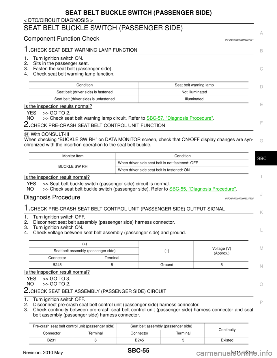
1.CHECK SEAT BELT WARNING LAMP FUNCTION
1. Turn ignition switch ON.
2. Sits in the passenger seat.
3. Fasten the seat belt (passenger side).
4. Check seat belt warning lamp function.
Is the inspection results normal?
YES >> GO TO 2.
NO >> Check seat belt warning lamp circuit. Refer to SBC-57, "
Diagnosis Procedure".
2.CHECK PRE-CRASH SEAT BELT CONTROL UNIT FUNCTION
With CONSULT-III
When checking “BUCKLE SW RH” on DATA MONITOR scr een, check that ON/OFF display changes are syn-
chronized with the insertion operation to the seat belt buckle.
Is the inspection result normal?
YES >> Seat belt buckle switch (passenger side) circuit is normal.
NO >> Check seat belt buckle switch (passenger side). Refer to SBC-55, "
Diagnosis Procedure".
Diagnosis ProcedureINFOID:0000000006237935
1.CHECK PRE-CRASH SEAT BELT CONTROL UNIT (PASSENGER SIDE) OUTPUT SIGNAL
1. Turn ignition switch OFF.
2. Disconnect seat belt assembly (passenger side) harness connector.
3. Turn ignition switch ON.
4. Check voltage between seat belt assembly (passenger side) and ground.
Is the inspection result normal?
YES >> GO TO 3.
NO >> GO TO 2.
2.CHECK SEAT BELT ASSEMBLY (PASSENGER SIDE) CIRCUIT
1. Turn ignition switch OFF.
2. Disconnect pre-crash seat belt contro l unit (passenger side) harness connector.
3. Check continuity between pre-crash seat belt c ontrol unit (passenger side) harness connector and seat
belt assembly (passenger side) harness connector.
Condition Seat belt warning lamp
Seat belt (driver side) is fastened Not illuminated
Seat belt (driver side) is unfastened Illuminated
Monitor item Condition
BUCKLE SW RH When driver side seat belt is not fastened: OFF
When driver side seat belt is fastened: ON
(+)
(–)Voltage (V)
(Approx.)
Seat belt assembly (passenger side)
Connector Terminal B245 5 Ground 5
Pre-crash seat belt control unit (passenger side) Seat belt assembly (passenger side) Continuity
Connector Terminal Connector Terminal
B2316B2455Existed
Revision: 2010 May2011 QX56
Page 4353 of 5598

SBC-56
< DTC/CIRCUIT DIAGNOSIS >
SEAT BELT BUCKLE SWITCH (PASSENGER SIDE)
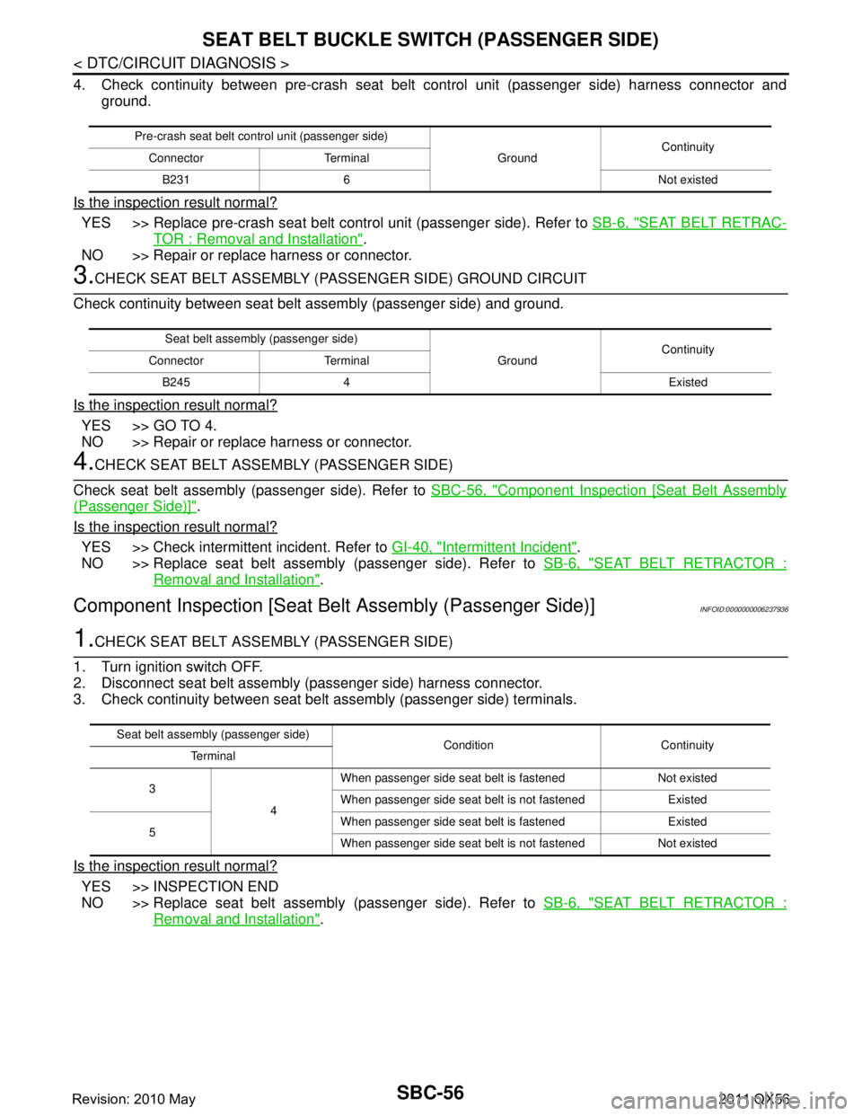
4. Check continuity between pre-crash seat belt control unit (passenger side) harness connector and
ground.
Is the inspection result normal?
YES >> Replace pre-crash seat belt control unit (passenger side). Refer to SB-6, "SEAT BELT RETRAC-
TOR : Removal and Installation".
NO >> Repair or replace harness or connector.
3.CHECK SEAT BELT ASSEMBLY (PA SSENGER SIDE) GROUND CIRCUIT
Check continuity between seat belt assembly (passenger side) and ground.
Is the inspection result normal?
YES >> GO TO 4.
NO >> Repair or replace harness or connector.
4.CHECK SEAT BELT ASSEMBLY (PASSENGER SIDE)
Check seat belt assembly (passenger side). Refer to SBC-56, "
Component Inspection [Seat Belt Assembly
(Passenger Side)]".
Is the inspection result normal?
YES >> Check intermittent incident. Refer to GI-40, "Intermittent Incident".
NO >> Replace seat belt assembly (passenger side). Refer to SB-6, "
SEAT BELT RETRACTOR :
Removal and Installation".
Component Inspection [Seat Belt Assembly (Passenger Side)]INFOID:0000000006237936
1.CHECK SEAT BELT ASSEMBLY (PASSENGER SIDE)
1. Turn ignition switch OFF.
2. Disconnect seat belt assembly (passenger side) harness connector.
3. Check continuity between seat belt assembly (passenger side) terminals.
Is the inspection result normal?
YES >> INSPECTION END
NO >> Replace seat belt assembly (passenger side). Refer to SB-6, "
SEAT BELT RETRACTOR :
Removal and Installation".
Pre-crash seat belt control unit (passenger side)
GroundContinuity
Connector Terminal
B231 6 Not existed
Seat belt assembly (passenger side) GroundContinuity
Connector Terminal
B245 4 Existed
Seat belt assembly (passenger side) Condition Continuity
Te r m i n a l
3 4When passenger side seat belt is fastened Not existed
When passenger side seat belt is not fastened Existed
5 When passenger side seat belt is fastened Existed
When passenger side seat belt is not fastened Not existed
Revision: 2010 May2011 QX56
Page 4354 of 5598

SEAT BELT WARNING LAMP CIRCUITSBC-57
< DTC/CIRCUIT DIAGNOSIS >
C
DE
F
G
I
J
K L
M A
B
SBC
N
O P
SEAT BELT WARNING LAMP CIRCUIT
Component Function CheckINFOID:0000000006237937
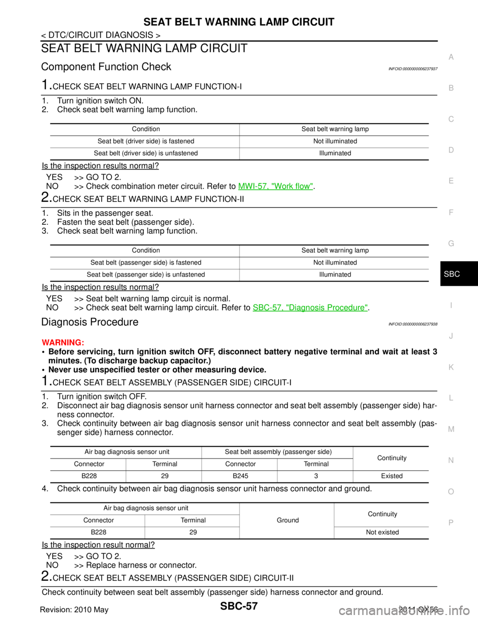
1.CHECK SEAT BELT WARNI NG LAMP FUNCTION-I
1. Turn ignition switch ON.
2. Check seat belt warning lamp function.
Is the inspection results normal?
YES >> GO TO 2.
NO >> Check combination meter circuit. Refer to MWI-57, "
Work flow".
2.CHECK SEAT BELT WARNING LAMP FUNCTION-II
1. Sits in the passenger seat.
2. Fasten the seat belt (passenger side).
3. Check seat belt warning lamp function.
Is the inspection results normal?
YES >> Seat belt warning lamp circuit is normal.
NO >> Check seat belt warning lamp circuit. Refer to SBC-57, "
Diagnosis Procedure".
Diagnosis ProcedureINFOID:0000000006237938
WARNING:
Before servicing, turn ignition switch OFF, disconnect battery negative terminal and wait at least 3
minutes. (To discharge backup capacitor.)
Never use unspecified tester or other measuring device.
1.CHECK SEAT BELT ASSEMBLY (PASSENGER SIDE) CIRCUIT-I
1. Turn ignition switch OFF.
2. Disconnect air bag diagnosis sensor unit harness connec tor and seat belt assembly (passenger side) har-
ness connector.
3. Check continuity between air bag diagnosis sensor unit harness connector and seat belt assembly (pas-
senger side) harness connector.
4. Check continuity between air bag diagnosis sensor unit harness connector and ground.
Is the inspection result normal?
YES >> GO TO 2.
NO >> Replace harness or connector.
2.CHECK SEAT BELT ASSEMBLY (PASSENGER SIDE) CIRCUIT-II
Check continuity between seat belt assemb ly (passenger side) harness connector and ground.
Condition Seat belt warning lamp
Seat belt (driver side) is fastened Not illuminated
Seat belt (driver side) is unfastened Illuminated
Condition Seat belt warning lamp
Seat belt (passenger side) is fastened Not illuminated
Seat belt (passenger side) is unfastened Illuminated
Air bag diagnosis sensor unit Seat belt assembly (passenger side) Continuity
Connector Terminal Connector Terminal
B228 29 B245 3 Existed
Air bag diagnosis sensor unit GroundContinuity
Connector Terminal
B228 29 Not existed
Revision: 2010 May2011 QX56
Page 4355 of 5598

SBC-58
< DTC/CIRCUIT DIAGNOSIS >
SEAT BELT WARNING LAMP CIRCUIT
Is the inspection result normal?
YES >> GO TO 3.
NO >> Repair or replace harness or connector.
3.CHECK SEAT BELT ASSEMBLY (PASSENGER SIDE)
Check seat belt assembly (passenger side).
Refer to SBC-58, "
Component Inspection [Seat Belt Assembly (Passenger Side)]".
Is the inspection result normal?
YES >> GO TO 4.
NO >> Replace seat belt assembly (passenger side). Refer to SB-6, "
SEAT BELT RETRACTOR :
Removal and Installation".
4.CHECK SEAT BELT WARNING LAMP CIRCUIT
1. Disconnect combination meter harness connector.
2. Check continuity between air bag diagnosis sensor unit harness connector and combination meter har- ness connector.
3. Check continuity between seat belt warning unit and ground.
Is the inspection results normal?
YES >> GO TO 5.
NO >> Replace harness or connector.
5.CHECK COMBINATION METER POWE R SUPPLY AND GROUND CIRCUIT
Check combination meter power supply and ground circuit.
Refer to MWI-64, "
COMBINATION METER : Diagnosis Procedure".
Is the inspection result normal?
YES >> GO TO 6.
NO >> Repair or replace harness or connector.
6.REPLACE COMBINATION METER
Replace combination meter.
Refer to MWI-85, "
Removal and Installation".
Is the inspection result normal?
YES >> INSPECTION END
NO >> Replace air bag diagnosis sensor unit. Refer to SR-26, "
Removal and Installation".
Component Inspection [Seat Belt Assembly (Passenger Side)]INFOID:0000000006237939
1.CHECK SEAT BELT ASSEMBLY (PASSENGER SIDE)
1. Turn ignition switch OFF.
2. Disconnect seat belt assembly (passenger side) harness connector.
3. Check continuity between seat belt assembly (passenger side) terminals.
Seat belt assembly (passenger side)
GroundContinuity
Connector Terminal
B245 4 Existed
Air bag diagnosis sensor unit Combination meter Continuity
Connector Terminal Connector Terminal
M5924M3436Existed
Air bag diagnosis sensor unit GroundContinuity
Connector Terminal
M59 24 Not existed
Revision: 2010 May2011 QX56
Page 4357 of 5598

SBC-60
< SYMPTOM DIAGNOSIS >
PRE-CRASH SEAT BELT DOSE NOT OPERATE
SYMPTOM DIAGNOSIS
PRE-CRASH SEAT BELT DOSE NOT OPERATE
Diagnosis ProcedureINFOID:0000000006237940
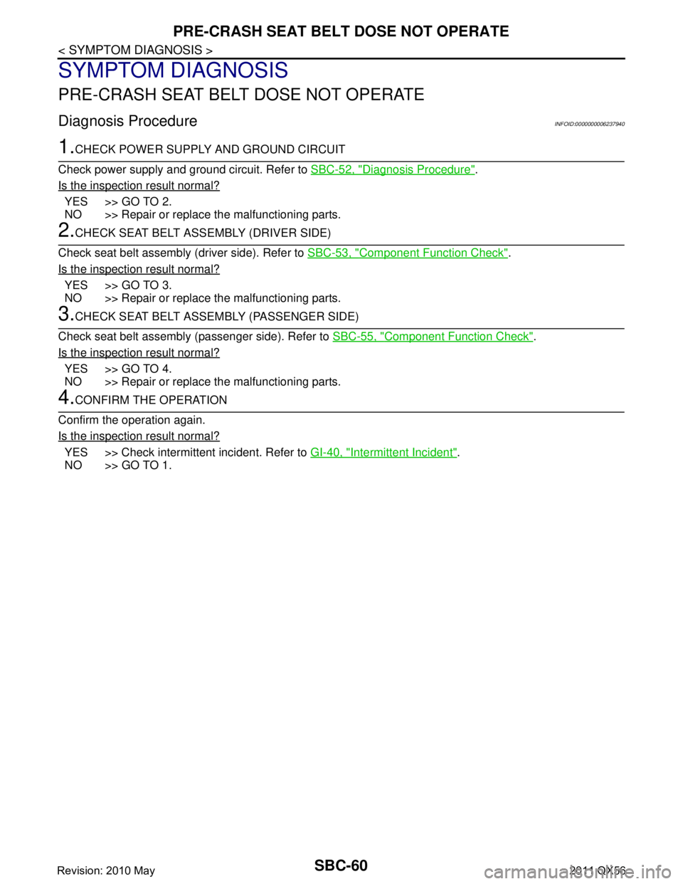
1.CHECK POWER SUPPLY AND GROUND CIRCUIT
Check power supply and ground circuit. Refer to SBC-52, "
Diagnosis Procedure".
Is the inspection result normal?
YES >> GO TO 2.
NO >> Repair or replace the malfunctioning parts.
2.CHECK SEAT BELT ASSEMBLY (DRIVER SIDE)
Check seat belt assembly (driver side). Refer to SBC-53, "
Component Function Check".
Is the inspection result normal?
YES >> GO TO 3.
NO >> Repair or replace the malfunctioning parts.
3.CHECK SEAT BELT ASSEMBLY (PASSENGER SIDE)
Check seat belt assembly (passenger side). Refer to SBC-55, "
Component Function Check".
Is the inspection result normal?
YES >> GO TO 4.
NO >> Repair or replace the malfunctioning parts.
4.CONFIRM THE OPERATION
Confirm the operation again.
Is the inspection result normal?
YES >> Check intermittent incident. Refer to GI-40, "Intermittent Incident".
NO >> GO TO 1.
Revision: 2010 May2011 QX56
Page 4363 of 5598

SCS-3
C
DF
G H
I
J
K L
M A
B
SCS
N
O P
N
Description ..........................................................
....
87
DTC Logic ...............................................................87
Diagnosis Procedure ...............................................87
U1010 CONTROL UNIT (CAN) ..........................88
Description .......................................................... ....88
DTC Logic ...............................................................88
Diagnosis Procedure ...............................................88
POWER SUPPLY AND GROUND CIRCUIT ......89
Diagnosis Procedure .......................................... ....89
CK SUSP INDICATOR LAMP CIRCUIT ............90
Description .......................................................... ....90
Component Function Check ....................................90
Diagnosis Procedure ...............................................90
SYMPTOM DIAGNOSIS ..............................91
VEHICLE HEIGHT CANNOT BE RAISED ..... ....91
Description .......................................................... ....91
Diagnosis Procedure ...............................................91
VEHICLE HEIGHT CANNOT BE LOWERED ....92
Description ..............................................................92
Diagnosis Procedure ........................................... ....92
CK SUSP INDICATOR LAMP DOES NOT
TURN OFF ........................................ .................
93
Description ........................................................... ....93
Diagnosis Procedure ...............................................93
REMOVAL AND INSTALLATION ...............94
AIR LEVELIZER CONTROL MODULE ............94
Exploded View ..................................................... ....94
Removal and Installation .........................................94
Adjustment ...............................................................94
AIR COMPRESSOR/AIR TUBE ........................95
Exploded View .........................................................95
Removal and Installation .........................................95
Inspection ................................................................97
VEHICLE HEIGHT SENSOR ............................98
Exploded View .........................................................98
Removal and Installation .........................................98
Adjustment ...............................................................99
Revision: 2010 May2011 QX56
Page 4380 of 5598
![INFINITI QX56 2011 Factory Service Manual
SCS-20
< BASIC INSPECTION >[HBMC]
CHECK INTERNAL LEAKAGE
CHECK INTERNAL LEAKAGE
Work ProcedureINFOID:0000000006256012
CAUTION:
Clean surrounding areas of
oil injection jack using steam before sta INFINITI QX56 2011 Factory Service Manual
SCS-20
< BASIC INSPECTION >[HBMC]
CHECK INTERNAL LEAKAGE
CHECK INTERNAL LEAKAGE
Work ProcedureINFOID:0000000006256012
CAUTION:
Clean surrounding areas of
oil injection jack using steam before sta](/manual-img/42/57033/w960_57033-4379.png)
SCS-20
< BASIC INSPECTION >[HBMC]
CHECK INTERNAL LEAKAGE
CHECK INTERNAL LEAKAGE
Work ProcedureINFOID:0000000006256012
CAUTION:
Clean surrounding areas of
oil injection jack using steam before starting operation, since there may
be mud on it.
Clean oil pressure gauge (special service tool: KV40108000) jack with steam before use.
1. Remove protector of PPMU.
2. Remove cap of oil injection jack.
3. Install an oil pressure gauge (SST: KV40108000) (A) to oil injec- tion jack.
CAUTION:
Jack must be securely inserted until a click sound can beheard.
Pressure reducing valve (B) of the oil pressure gauge
must be closed.
4. Loosen needle valves A, C, and E of PPMU by approximately 2 rotations. CAUTION:
Never loosen the needle valve more than required.
5. Lift up the vehicle. CAUTION:
Check that tires never contact the ground.
6. Tighten needle valves C and E of PPMU.
7. Loosen lock nut of needle valve D of PPMU and then tighten needle valve D.
8. Lift down the vehicle. CAUTION:
Check that the lift is fully lowered.
9. Write down a value of the oil pressure gauge after 5 minutes.
10. Tighten needle valve A of PPMU.
11. Loosen lock nut of needle valve B of PPMU and then tighten needle valve B.
12. Loosen needle valve C of PPMU by approximately 2 rotations. CAUTION:
Never loosen the needle valve more than required.
13. Read a value of oil pressure gauge.
14. Compare difference of reading with pressure reading in step 9.
15. Tighten needle valves A, C, and E of PPMU to the specified torque.
16. Loosen needle valves B and D of PPMU by approximatel y 2 rotations and then tighten lock nut to the
specified torque.
CAUTION:
Never loosen the needle valve more than required.
JSEIA0186ZZ
Pressure difference
0.1 MPa or more : Normal
0.1 MPa or less : Malfunction
: 8.3 N·m (0.85 kg-m, 73 in-lb)
JSEIA0187ZZ
Revision: 2010 May2011 QX56
Page 4382 of 5598
![INFINITI QX56 2011 Factory Service Manual
SCS-22
< BASIC INSPECTION >[HBMC]
CHECK FOR MALFUNCTION
CHECK FOR MALFUNCTION
Work ProcedureINFOID:0000000006256013
CAUTION:
Clean surrounding areas of
oil injection jack using steam before start INFINITI QX56 2011 Factory Service Manual
SCS-22
< BASIC INSPECTION >[HBMC]
CHECK FOR MALFUNCTION
CHECK FOR MALFUNCTION
Work ProcedureINFOID:0000000006256013
CAUTION:
Clean surrounding areas of
oil injection jack using steam before start](/manual-img/42/57033/w960_57033-4381.png)
SCS-22
< BASIC INSPECTION >[HBMC]
CHECK FOR MALFUNCTION
CHECK FOR MALFUNCTION
Work ProcedureINFOID:0000000006256013
CAUTION:
Clean surrounding areas of
oil injection jack using steam before starting operation, since there may
be mud on it.
Clean oil pressure gauge (special service tool: KV40108000) jack with steam before use.
1. Remove protector of PPMU.
2. Remove cap of oil injection jack.
3. Install an oil pressure gauge (SST: KV40108000) (A) to oil injec- tion jack.
CAUTION:
Jack must be securely inserted until a click sound can beheard.
Pressure reducing valve (B) of the oil pressure gauge
must be closed.
4. Loosen needle valves A, C, and E of PPMU by approximately 2 rotations.
CAUTION:
Never loosen the needle valve more than required.
5. Lift up the vehicle. CAUTION:
Check that tires never contact the ground.
6. Tighten needle valves A and C of PPMU.
7. Loosen lock nuts of needle valves B and D of PPMU and then tighten needle valves B and D.
8. Write down a value of the oil pressure gauge.
9. Lift down the vehicle. CAUTION:
Check that the lift is fully lowered.
10. Read a value of oil pressure gauge.
11. Compare difference of reading with pressure reading in step 8.
12. Tighten needle valves A, C, and E of PPMU to the specified torque.
13. Loosen needle valves B and D of PPMU by approximatel y 2 rotations and then tighten lock nut to the
specified torque.
CAUTION:
Never loosen the needle valve more than required.
JSEIA0186ZZ
Pressure change
Pressure increases : PPMU malfunction
Pressure does not change : Shock absorber malfunction
Tightening torque : 8.3 N· m (0.85 kg-m, 73 in-lb)
Tightening torque : 20 N·m (2.0 kg-m, 15 ft-lb)
JSEIA0187ZZ
Revision: 2010 May2011 QX56