2011 INFINITI QX56 ground
[x] Cancel search: groundPage 4260 of 5598
REAR SUSPENSION ASSEMBLYRSU-5
< PERIODIC MAINTENANCE >
C
DF
G H
I
J
K L
M A
B
RSU
N
O P
PERIODIC MAINTENANCE
REAR SUSPENSION ASSEMBLY
InspectionINFOID:0000000006225660
MOUNTING INSPECTION
Check the mounting conditions (looseness, backlash) of each component and component conditions (wear,
damage) are normal.
BALL JOINT AXIAL END PLAY
Measure axial end play by placing and moving up/down with an iron bar or equivalent between suspension
arm or front lower link and axle assembly.
CAUTION:
• Never depress brake pedal when measuring.
Never perform with tires on level ground.
Be careful not to damage ball joint boot.
SHOCK ABSORBER
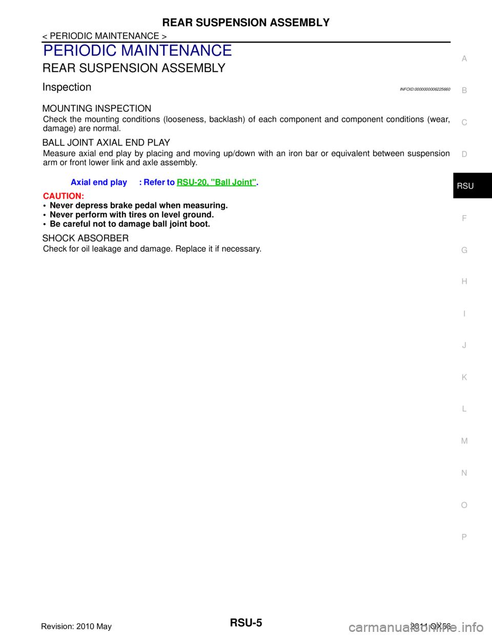
Check for oil leakage and damage. Replace it if necessary. Axial end play : Refer to
RSU-20, "
Ball Joint".
Revision: 2010 May2011 QX56
Page 4264 of 5598
REAR LOWER LINK & COIL SPRINGRSU-9
< REMOVAL AND INSTALLATION >
C
DF
G H
I
J
K L
M A
B
RSU
N
O P
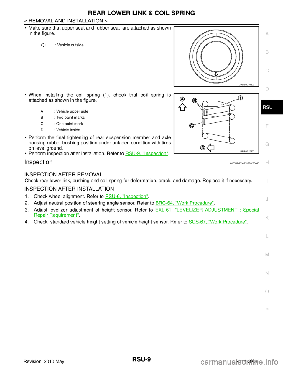
Make sure that upper seat and rubber seat are attached as shown in the figure.
When installing the coil spring (1), check that coil spring is attached as shown in the figure.
Perform the final tightening of rear suspension member and axle housing rubber bushing position under unladen condition with tires
on level ground.
Perform inspection after installation. Refer to RSU-9, "
Inspection".
InspectionINFOID:0000000006225665
INSPECTION AFTER REMOVAL
Check rear lower link, bushing and coil spring for defor mation, crack, and damage. Replace it if necessary.
INSPECTION AFTER INSTALLATION
1. Check wheel alignment. Refer to RSU-6, "Inspection".
2. Adjust neutral position of steering angle sensor. Refer to BRC-64, "
Work Procedure".
3. Adjust levelizer adjustment of height sensor. Refer to EXL-61, "
LEVELIZER ADJUSTMENT : Special
Repair Requirement".
4. Check standard vehicle height setting of vehicle height sensor. Refer to SCS-67, "
Work Procedure".
: Vehicle outside
JPEIB0219ZZ
A : Vehicle upper side
B : Two paint marks
C : One paint mark
D : Vehicle inside
JPEIB0237ZZ
Revision: 2010 May2011 QX56
Page 4266 of 5598
REAR SHOCK ABSORBERRSU-11
< REMOVAL AND INSTALLATION >
C
DF
G H
I
J
K L
M A
B
RSU
N
O P
Inadvertent piping removal causes fluid to splatter.
2. Remove tires with power tool. Refer to WT-64, "
Removal and Installation".
3. Remove height sensor from rear lower link (right side). Refer to EXL-136, "
Removal and Installation".
4. Remove vehicle height sensor from rear lower link (left side). Refer to SCS-98, "
Removal and Installa-
tion".
5. Remove air tube from shock absorber assembly. Refer to SCS-95, "
Removal and Installation".
6. Remove middle tube assembly from shock absorber assembly. (With HBMC) Refer to SCS-44, "
REAR
TUBE ASSEMBLY : Removal and Installation".
7. Remove shock absorber mounting bolt (lower side).
8. Remove piston rod lock nut.
9. Remove bracket, bushings, and shock absorber. (With HBMC)
10. Remove washers, bushings, and shock absorber. (Without HBMC)
11. Perform inspection after removal. Refer to RSU-11, "
Inspection and Adjustment".
INSTALLATION
Note the following, and install in the reverse order of removal.
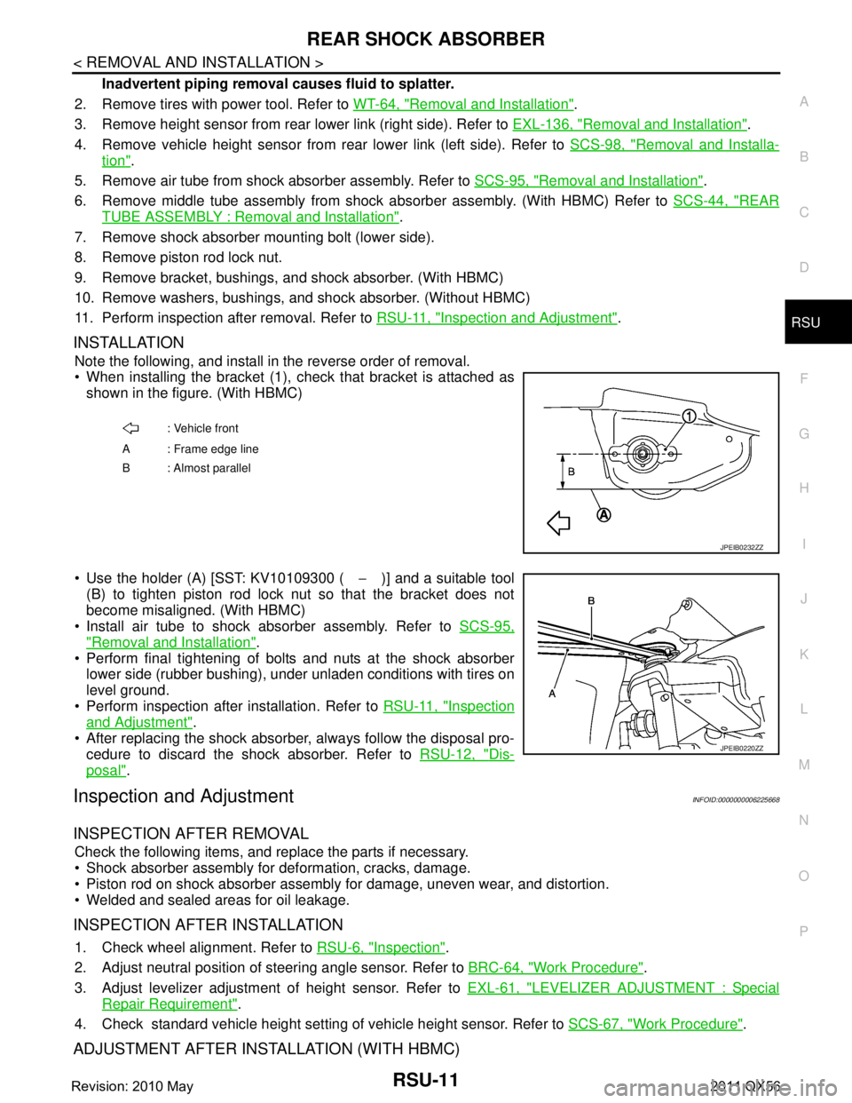
When installing the bracket (1), check that bracket is attached as
shown in the figure. (With HBMC)
Use the holder (A) [SST: KV10109300 ( −)] and a suitable tool
(B) to tighten piston rod lock nut so that the bracket does not
become misaligned. (With HBMC)
Install air tube to shock absorber assembly. Refer to SCS-95,
"Removal and Installation".
Perform final tightening of bolts and nuts at the shock absorber
lower side (rubber bushing), under unladen conditions with tires on
level ground.
Perform inspection after installation. Refer to RSU-11, "
Inspection
and Adjustment".
After replacing the shock absorber, always follow the disposal pro- cedure to discard the shock absorber. Refer to RSU-12, "
Dis-
posal".
Inspection and AdjustmentINFOID:0000000006225668
INSPECTION AFTER REMOVAL
Check the following items, and replace the parts if necessary.
Shock absorber assembly for deformation, cracks, damage.
Piston rod on shock absorber assembly for damage, uneven wear, and distortion.
Welded and sealed areas for oil leakage.
INSPECTION AFTER INSTALLATION
1. Check wheel alignment. Refer to RSU-6, "Inspection".
2. Adjust neutral position of steering angle sensor. Refer to BRC-64, "
Work Procedure".
3. Adjust levelizer adjustment of height sensor. Refer to EXL-61, "
LEVELIZER ADJUSTMENT : Special
Repair Requirement".
4. Check standard vehicle height setting of vehicle height sensor. Refer to SCS-67, "
Work Procedure".
ADJUSTMENT AFTER INSTALLATION (WITH HBMC)
: Vehicle front
A : Frame edge line
B: Almost parallel
JPEIB0232ZZ
JPEIB0220ZZ
Revision: 2010 May2011 QX56
Page 4268 of 5598
SUSPENSION ARMRSU-13
< REMOVAL AND INSTALLATION >
C
DF
G H
I
J
K L
M A
B
RSU
N
O P
SUSPENSION ARM
Exploded ViewINFOID:0000000006225670
Removal and InstallationINFOID:0000000006225671
REMOVAL
1. Remove tires with power tool. Refer to WT-64, "Removal and Installation".
2. Remove rear suspension member assembly. Refer to RSU-18, "
Removal and Installation".
3. Remove bumper rubber from frame, usi ng a socket (commercial service tool).
4. Remove suspension arm from axle housing. Refer to RAX-7, "
Removal and Installation".
5. Remove suspension arm mounting bolts, nuts, and stopper rubber from rear suspension member.
6. Remove suspension arm.
7. Perform inspection after removal. Refer to RSU-13, "
Inspection and Adjustment".
INSTALLATION
Note the following and, install in the reverse order of removal.
Perform final tightening of rear suspension mem ber installation position (rubber bussing), under unladen
conditions with tires on level ground.
Perform inspection after installation. Refer to RSU-13, "
Inspection and Adjustment".
Perform adjustment after installation. (With HBMC) Refer to RSU-13, "
Inspection and Adjustment".
Inspection and AdjustmentINFOID:0000000006225672
INSPECTION AFTER REMOVAL
Appearance
Check the following items, and replace the part if necessary.
Suspension arm and bushing for deformation, cracks or damage.
Boot of ball joint for cracks or damage, and also for grease leakage.
Ball Joint Inspection
Manually move ball stud to confirm it moves smoothly with no binding.
Swing Torque Inspection
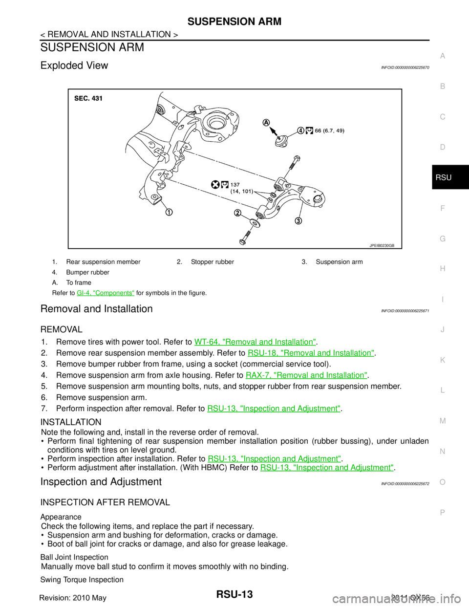
1. Rear suspension member 2. Stopper rubber 3. Suspension arm
4. Bumper rubber
A. To frame
Refer to GI-4, "
Components" for symbols in the figure.
JPEIB0230GB
Revision: 2010 May2011 QX56
Page 4270 of 5598
FRONT LOWER LINKRSU-15
< REMOVAL AND INSTALLATION >
C
DF
G H
I
J
K L
M A
B
RSU
N
O P
FRONT LOWER LINK
Exploded ViewINFOID:0000000006225673
Removal and InstallationINFOID:0000000006225674
REMOVAL
1. Remove tires with power tool. Refer to WT-64, "Removal and Installation".
2. Set suitable jack under rear lower link.
3. Remove shock absorber mounting bolts from front lower link. Refer to RSU-10, "
Exploded View".
4. Remove stabilizer connecting rod. (Without HBMC) Refer to RSU-17, "
Removal and Installation".
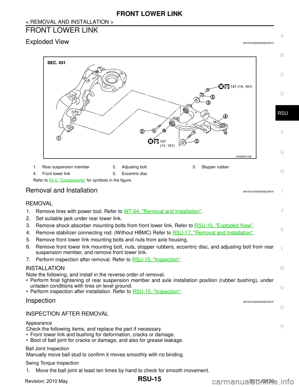
5. Remove front lower link mounting bolts and nuts from axle housing.
6. Remove front lower link mounting bolt, nuts, stopper rubbers, eccentric disc, and adjusting bolt from rear
suspension member, and remove front lower link.
7. Perform inspection after removal. Refer to RSU-15, "
Inspection".
INSTALLATION
Note the following, and install in the reverse order of removal.
Perform final tightening of rear suspension mem ber and axle installation position (rubber bushing), under
unladen conditions with tires on level ground.
Perform inspection after installation. Refer to RSU-15, "
Inspection".
InspectionINFOID:0000000006225675
INSPECTION AFTER REMOVAL
Appearance
Check the following items, and replace the part if necessary.
Front lower link and bushing for deformation, cracks or damage.
Boot of ball joint for cracks or damage, and also for grease leakage.
Ball Joint Inspection
Manually move ball stud to confirm it moves smoothly with no binding.
Swing Torque Inspection
1. Move the ball joint at least ten times by hand to check for smooth movement.
1. Rear suspension member 2. Adjusting bolt 3. Stopper rubber
4. Front lower link 5. Eccentric disc
Refer to GI-4, "
Components" for symbols in the figure.
JPEIB0231GB
Revision: 2010 May2011 QX56
Page 4299 of 5598

SBC-2
DTC Logic ...............................................................38
Diagnosis Procedure ..............................................38
Component Inspection ............................................39
B2454 SEAT BLT PWR DR CIRC .....................41
DTC Logic ............................................................ ...41
Diagnosis Procedure ..............................................41
B2455 CONTROL UNIT DR ..............................42
DTC Logic ............................................................ ...42
Diagnosis Procedure ..............................................42
B2456 SEAT BLT PWR AS ...............................43
DTC Logic ............................................................ ...43
Diagnosis Procedure ..............................................43
B2457 CONTROL UNIT AS ...............................44
DTC Logic ............................................................ ...44
Diagnosis Procedure ..............................................44
B2458 LOCAL COMM .......................................45
DTC Logic ............................................................ ...45
Diagnosis Procedure ..............................................45
B2461 VHCL SPEED SIGNAL ..........................47
Description ........................................................... ...47
DTC Logic ...............................................................47
Diagnosis Procedure ..............................................47
B2463 ROLLOVER SIGNAL .............................48
Description ........................................................... ...48
DTC Logic ...............................................................48
Diagnosis Procedure ..............................................48
B2466 DR/AS CONTROL UNIT ........................49
DTC Logic ............................................................ ...49
Diagnosis Procedure ..............................................49
B2470 SYS HEAT PROTC DR ..........................50
Description ........................................................... ...50
DTC Logic ...............................................................50
Diagnosis Procedure ..............................................50
B2471 SYS HEAT PROTC AS ..........................51
Description ........................................................... ...51
DTC Logic ...............................................................51
Diagnosis Procedure ............................................ ...51
POWER SUPPLY AND GROUND CIRCUIT .....52
Diagnosis Procedure ............................................ ...52
SEAT BELT BUCKLE SWITCH (DRIVER
SIDE) ..................................................................
53
Component Function Check ................................ ...53
Diagnosis Procedure ...............................................53
Component Inspection [Seat Belt Assembly (Driv-
er Side)] ..................................................................
54
SEAT BELT BUCKLE SWITCH (PASSEN-
GER SIDE) .........................................................
55
Component Function Check ................................ ...55
Diagnosis Procedure ...............................................55
Component Inspection [Seat Belt Assembly (Pas-
senger Side)] ...........................................................
56
SEAT BELT WARNING LAMP CIRCUIT ..........57
Component Function Check ................................ ...57
Diagnosis Procedure ...............................................57
Component Inspection [Seat Belt Assembly (Pas-
senger Side)] ...........................................................
58
SYMPTOM DIAGNOSIS ............................60
PRE-CRASH SEAT BELT DOSE NOT OPER-
ATE ................................................................. ...
60
Diagnosis Procedure ............................................ ...60
SEAT BELT WARNING LAMP DOES NOT
TURN OFF .........................................................
61
Diagnosis Procedure ............................................ ...61
SEAT BELT WARNING LAMP DOES NOT
TURN ON ...........................................................
62
Diagnosis Procedure ............................................ ...62
REMOVAL AND INSTALLATION ..............63
BRAKE PEDAL STROKE SENSOR .............. ...63
Exploded View ..................................................... ...63
Removal and Installation .........................................63
Revision: 2010 May2011 QX56
Page 4311 of 5598
SBC-14
< ECU DIAGNOSIS INFORMATION >
PRE-CRASH SEAT BELT CONTROL UNIT (DRIVER SIDE)
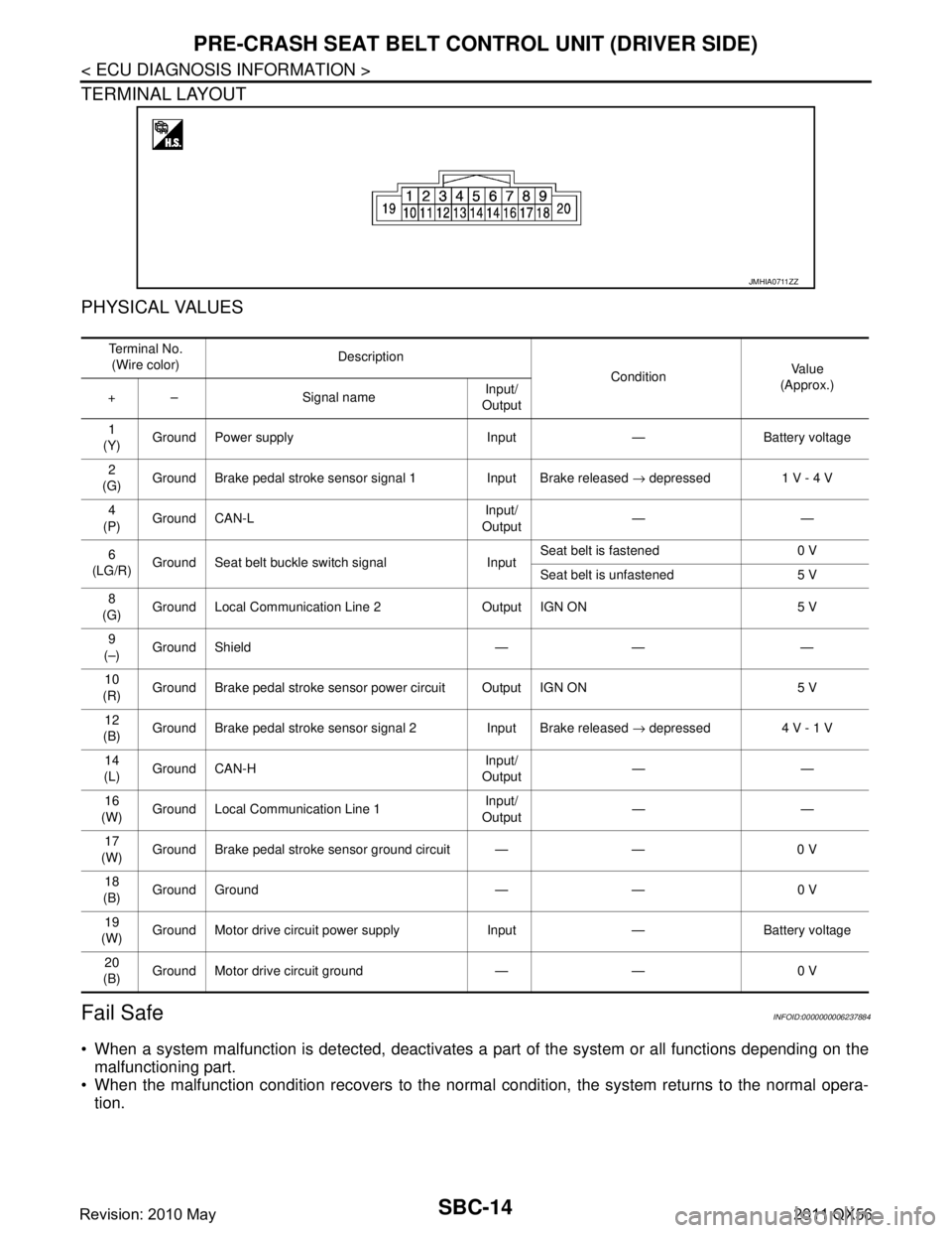
TERMINAL LAYOUT
PHYSICAL VALUES
Fail SafeINFOID:0000000006237884
When a system malfunction is detected, deactivates a part of the system or all functions depending on the
malfunctioning part.
When the malfunction condition recovers to the normal condition, the system returns to the normal opera-
tion.
JMHIA0711ZZ
Te r m i n a l N o .
(Wire color) Description
ConditionVa l u e
(Approx.)
+ – Signal name Input/
Output
1
(Y) Ground Power supply Input — Battery voltage
2
(G) Ground Brake pedal stroke sensor signal 1 Input Brake released
→ depressed 1 V - 4 V
4
(P) Ground CAN-L Input/
Output ——
6
(LG/R) Ground Seat belt buckle switch signal Input Seat belt is fastened 0 V
Seat belt is unfastened 5 V
8
(G) Ground Local Communication Line 2 Output IGN ON 5 V
9
(–) Ground Shield — — —
10
(R) Ground Brake pedal stroke sensor power circuit Output IGN ON 5 V
12
(B) Ground Brake pedal stroke sensor signal 2 Input Brake released
→ depressed 4 V - 1 V
14
(L) Ground CAN-H Input/
Output ——
16
(W) Ground Local Communication Line 1 Input/
Output ——
17
(W) Ground Brake pedal stroke sensor ground circuit — — 0 V
18
(B) Ground Ground — — 0 V
19
(W) Ground Motor drive circuit power supply Input — Battery voltage
20
(B) Ground Motor drive circuit ground — — 0 V
Revision: 2010 May2011 QX56
Page 4314 of 5598
PRE-CRASH SEAT BELT CONTROL UNIT (PASSENGER SIDE)
SBC-17
< ECU DIAGNOSIS INFORMATION >
C
D E
F
G
I
J
K L
M A
B
SBC
N
O P
PRE-CRASH SEAT BELT CONTROL UNIT (PASSENGER SIDE)
Reference ValueINFOID:0000000006237886
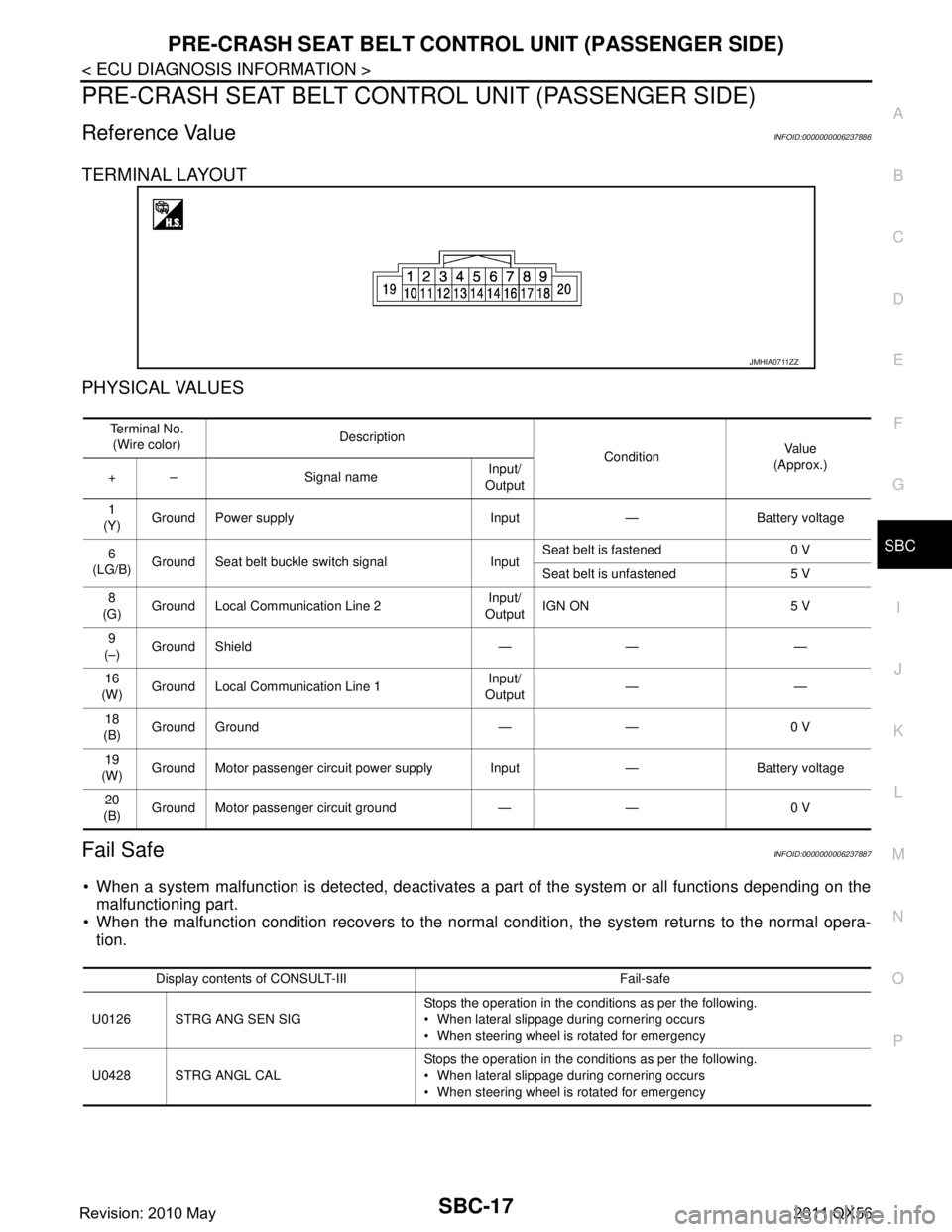
TERMINAL LAYOUT
PHYSICAL VALUES
Fail SafeINFOID:0000000006237887
When a system malfunction is detected, deactivates a part of the system or all functions depending on the
malfunctioning part.
When the malfunction condition recovers to the norma l condition, the system returns to the normal opera-
tion.
JMHIA0711ZZ
Te r m i n a l N o .
(Wire color) Description
ConditionVa l u e
(Approx.)
+ – Signal name Input/
Output
1
(Y) Ground Power supply Input — Battery voltage
6
(LG/B) Ground Seat belt buckle switch signal Input Seat belt is fastened 0 V
Seat belt is unfastened 5 V
8
(G) Ground Local Communication Line 2 Input/
Output IGN ON 5 V
9
(–) Ground Shield — — —
16
(W) Ground Local Communication Line 1
Input/
Output ——
18
(B) Ground Ground — — 0 V
19
(W) Ground Motor passenger circuit power supply Input — Battery voltage
20
(B) Ground Motor passenger circuit ground — — 0 V
Display contents of CONSULT-III Fail-safe
U0126 STRG ANG SEN SIG Stops the operation in the conditions as per the following.
When lateral slippage during cornering occurs
When steering wheel is rotated for emergency
U0428 STRG ANGL CAL Stops the operation in the conditions as per the following.
When lateral slippage during cornering occurs
When steering wheel is rotated for emergency
Revision: 2010 May2011 QX56