Page 4222 of 5598
RF-8
< ECU DIAGNOSIS INFORMATION >
SUNROOF SYSTEM
SUNROOF SYSTEM
Reference ValueINFOID:0000000006141227
TERMINAL LAYOUT
PHYSICAL VALUES
JMKIA2225ZZ
Te r m i n a l N o .(Wire color) Description
ConditionVoltage (V)
(Approx.)
+ – Signal name Input/
Output
1
(B) Ground Ground — — 0
3
(Y) Ground Retained power signal Input Ignition switch ON
12
Within 45 seconds after ignition
switch is turned to OFF
When driver side or passenger side
door is opened during retained pow-
er operation 0
5
(P) Ground Sunroof open signal Input Sunroof switch in following position
TILT DOWN
SLIDE OPEN
0
Ignition switch ON 12
6
(W) Ground Sunroof power supply Input — 12
8
(SB) Ground Vehicle speed signal (2-
pulse)
InputSpeedometer operated [When vehi-
cle speed is approx.40km/ h
(25MPH)]
10
(GR) Ground Sunroof close signal Input Sunroof switch in following position
TILT UP
SLIDE CLOSE
0
Ignition switch ON 12
ELF1080D
Revision: 2010 May2011 QX56
Page 4232 of 5598
RF-18
< DTC/CIRCUIT DIAGNOSIS >
POWER SUPPLY AND GROUND CIRCUIT
DTC/CIRCUIT DIAGNOSIS
POWER SUPPLY AND GROUND CIRCUIT
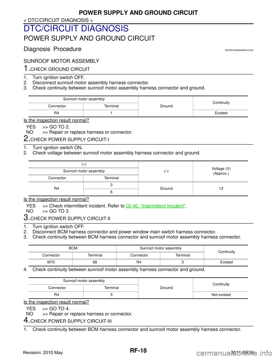
Diagnosis ProcedureINFOID:0000000006141232
SUNROOF MOTOR ASSEMBLY
1.CHECK GROUND CIRCUIT
1. Turn ignition switch OFF.
2. Disconnect sunroof motor assembly harness connector.
3. Check continuity between sunroof mo tor assembly harness connector and ground.
Is the inspection result normal?
YES >> GO TO 2.
NO >> Repair or replace harness or connector.
2.CHECK POWER SUPPLY CIRCUIT-I
1. Turn ignition switch ON.
2. Check voltage between sunroof moto r assembly harness connector and ground.
Is the inspection result normal?
YES >> Check intermittent incident. Refer to GI-40, "Intermittent Incident".
NO >> GO TO 3.
3.CHECK POWER SUPPLY CIRCUIT-II
1. Turn ignition switch OFF.
2. Disconnect BCM harness connector and power window main switch harness connector.
3. Check continuity between BCM harness connecto r and sunroof motor assembly harness connector.
4. Check continuity between sunroof mo tor assembly harness connector and ground.
Is the inspection result normal?
YES >> GO TO 4.
NO >> Repair or replace harness or connector.
4.CHECK POWER SUPPLY CIRCUIT-III
1. Check continuity between BCM harness connecto r and sunroof motor assembly harness connector.
Sunroof motor assembly
GroundContinuity
Connector Terminal
R4 1 Existed
(+) (–)Voltage (V)
(Approx.)
Sunroof motor assembly
Connector Terminal
R4 3
Ground 12
6
BCM Sunroof mo tor assembly
Continuity
Connector Terminal Connector Terminal
M70 68 R4 3 Existed
Sunroof motor assembly GroundContinuity
Connector Terminal
R4 3 Not existed
Revision: 2010 May2011 QX56
Page 4233 of 5598
POWER SUPPLY AND GROUND CIRCUITRF-19
< DTC/CIRCUIT DIAGNOSIS >
C
DE
F
G H
I
J
L
M A
B
RF
N
O P
2. Check continuity between sunroof mo tor assembly harness connector and ground.
Is the inspection result normal?
YES >> Check BCM power supply and ground circuit. Refer to BCS-75, "Diagnosis Procedure".
NO >> Repair or replace harness or connector.
BCM Sunroof mo tor assembly
Continuity
Connector Terminal Connector Terminal
M70 69 R4 6 Existed
Sunroof motor assembly GroundContinuity
Connector Terminal
R4 6 Not existed
Revision: 2010 May2011 QX56
Page 4234 of 5598
RF-20
< DTC/CIRCUIT DIAGNOSIS >
VEHICLE SPEED SIGNAL CIRCUIT
VEHICLE SPEED SIGNAL CIRCUIT
Component Function CheckINFOID:0000000006141233
1.CHECK SUNROOF MOTOR FUNCTION
Check tilt up/down & slide open/close operations with sunroof switch.
Is the inspection result normal?
YES >> GO TO 2.
NO >> Check sunroof switch. Refer to RF-21, "
DiagnosisProcedure".
2.CHECK SUNROOF MOTOR ASSEMBLY INPUT SIGNAL
1. Start engine.
2. Drive the vehicle at more than 40 km/h (25 MPH). CAUTION:
Always drive vehicle at a safe speed.
NOTE:
This procedure may be conducted with the drive wheel s lifted in the shop or by driving the vehicle.
If a road test is expected to be easier , it is unnecessary to lift the vehicle.
3. Check tilt up/down & slide open/clos e operations with sunroof switch.
Is the inspection result normal?
YES >> INSPECTION END
NO >> Refer to RF-20, "
DiagnosisProcedure".
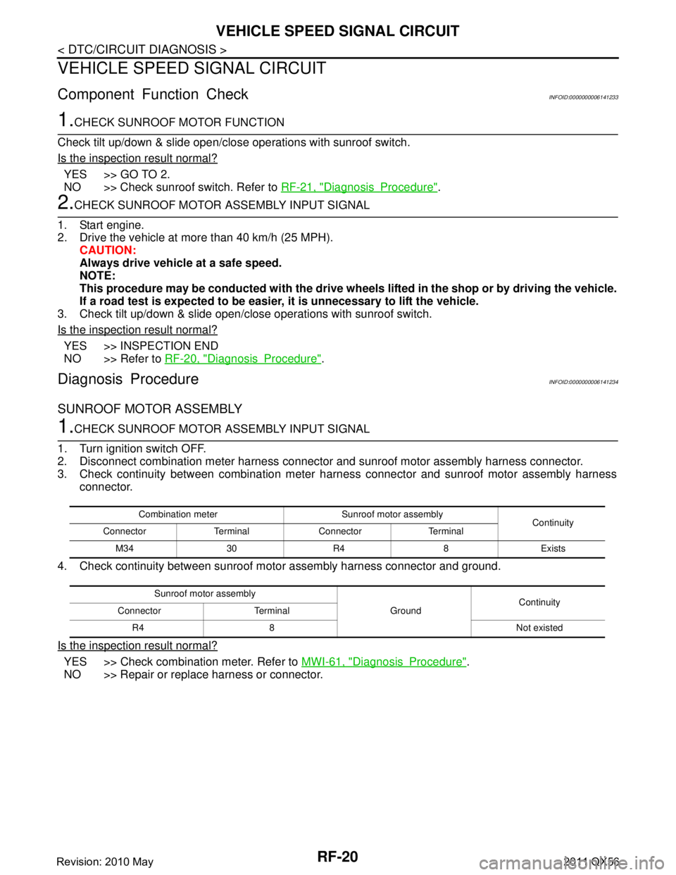
Diagnosis ProcedureINFOID:0000000006141234
SUNROOF MOTOR ASSEMBLY
1.CHECK SUNROOF MOTOR ASSEMBLY INPUT SIGNAL
1. Turn ignition switch OFF.
2. Disconnect combination meter harness connector and sunroof motor assembly harness connector.
3. Check continuity between combination meter harness connector and sunroof motor assembly harness connector.
4. Check continuity between sunroof mo tor assembly harness connector and ground.
Is the inspection result normal?
YES >> Check combination meter. Refer to MWI-61, "DiagnosisProcedure".
NO >> Repair or replace harness or connector.
Combination meter Sunroof motor assembly Continuity
Connector Terminal Connector Terminal
M34 30 R4 8 Exists
Sunroof motor assembly GroundContinuity
Connector Terminal
R4 8 Not existed
Revision: 2010 May2011 QX56
Page 4235 of 5598
SUNROOF SWITCHRF-21
< DTC/CIRCUIT DIAGNOSIS >
C
DE
F
G H
I
J
L
M A
B
RF
N
O P
SUNROOF SWITCH
Component Function CheckINFOID:0000000006141235
1.CHECK SUNROOF MOTOR FUNCTION
Check tilt up/down & slide open/close operations with sunroof switch.
Is the inspection result normal?
YES >> INSPECTION END
NO >> Refer to RF-21, "
DiagnosisProcedure".
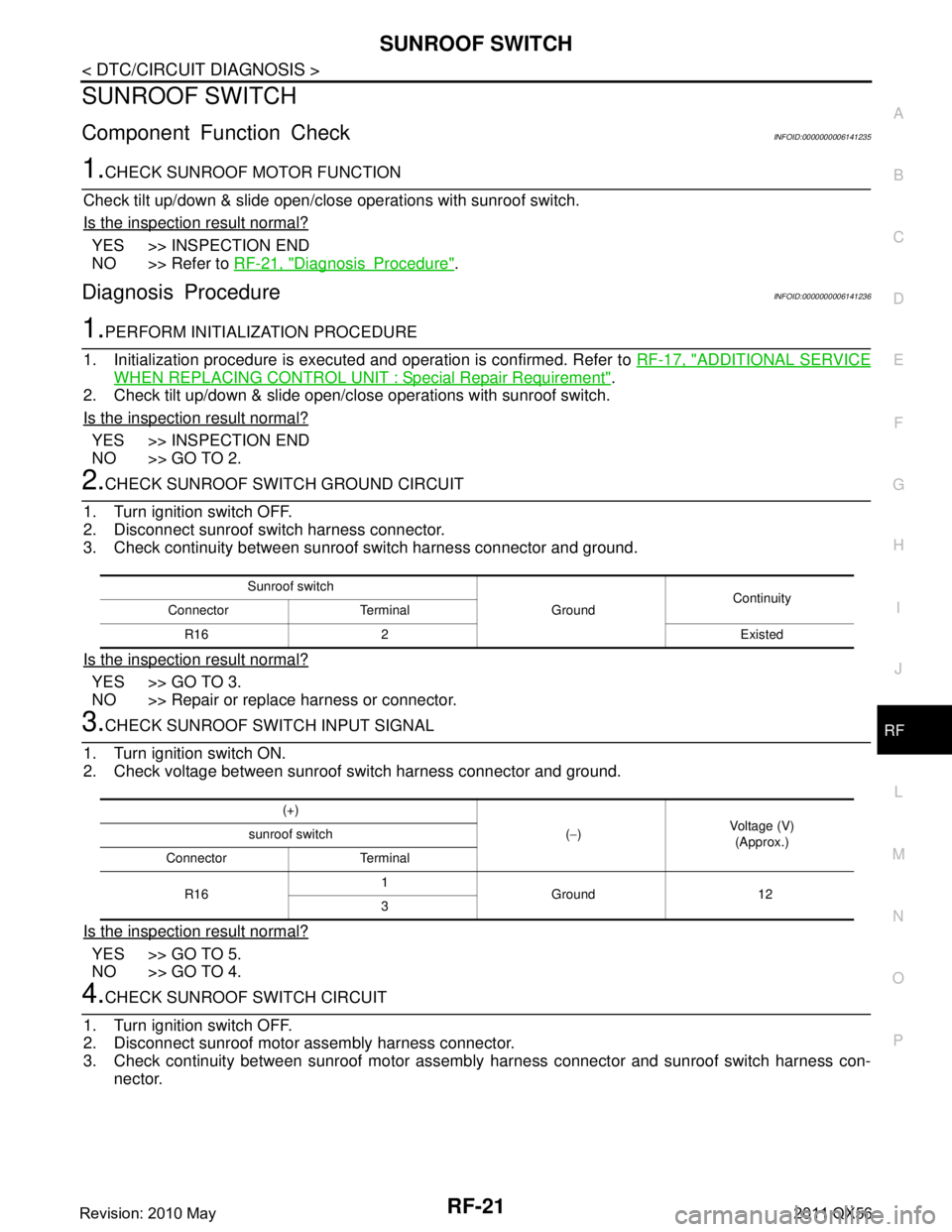
Diagnosis ProcedureINFOID:0000000006141236
1.PERFORM INITIALIZATION PROCEDURE
1. Initialization procedure is executed and operation is confirmed. Refer to RF-17, "
ADDITIONAL SERVICE
WHEN REPLACING CONTROL UNIT : Special Repair Requirement".
2. Check tilt up/down & slide open/close operations with sunroof switch.
Is the inspection result normal?
YES >> INSPECTION END
NO >> GO TO 2.
2.CHECK SUNROOF SWITCH GROUND CIRCUIT
1. Turn ignition switch OFF.
2. Disconnect sunroof switch harness connector.
3. Check continuity between sunroof switch harness connector and ground.
Is the inspection result normal?
YES >> GO TO 3.
NO >> Repair or replace harness or connector.
3.CHECK SUNROOF SWITCH INPUT SIGNAL
1. Turn ignition switch ON.
2. Check voltage between sunroof switch harness connector and ground.
Is the inspection result normal?
YES >> GO TO 5.
NO >> GO TO 4.
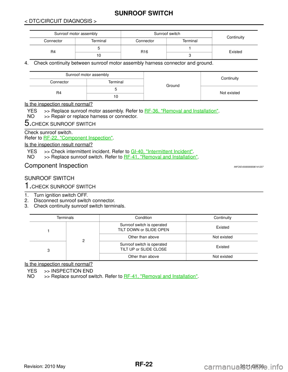
4.CHECK SUNROOF SWITCH CIRCUIT
1. Turn ignition switch OFF.
2. Disconnect sunroof motor assembly harness connector.
3. Check continuity between sunroof motor assemb ly harness connector and sunroof switch harness con-
nector.
Sunroof switch
GroundContinuity
Connector Terminal
R16 2 Existed
(+) (− ) Voltage (V)
(Approx.)
sunroof switch
Connector Terminal
R16 1
Ground 12
3
Revision: 2010 May2011 QX56
Page 4236 of 5598
RF-22
< DTC/CIRCUIT DIAGNOSIS >
SUNROOF SWITCH
4. Check continuity between sunroof motor assembly harness connector and ground.
Is the inspection result normal?
YES >> Replace sunroof motor assembly. Refer to RF-36, "Removal and Installation".
NO >> Repair or replace harness or connector.
5.CHECK SUNROOF SWITCH
Check sunroof switch.
Refer to RF-22, "
Component Inspection".
Is the inspection result normal?
YES >> Check intermittent incident. Refer to GI-40, "Intermittent Incident".
NO >> Replace sunroof switch. Refer to RF-41, "
Removal and Installation".
Component InspectionINFOID:0000000006141237
SUNROOF SWITCH
1.CHECK SUNROOF SWITCH
1. Turn ignition switch OFF.
2. Disconnect sunroof switch connector.
3. Check continuity sunroof switch terminals.
Is the inspection result normal?
YES >> INSPECTION END
NO >> Replace sunroof switch. Refer to RF-41, "
Removal and Installation".
Sunroof motor assembly Sunroof switch
Continuity
Connector Terminal Connector Terminal
R4 5
R16 1
Existed
10 3
Sunroof motor assembly GroundContinuity
Connector Terminal
R4 5
Not existed
10
Terminals Condition Continuity
1 2 Sunroof switch is operated
TILT DOWN or SLIDE OPEN Existed
Other than above Not existed
3 Sunroof switch is operated
TILT UP or SLIDE CLOSE Existed
Other than above Not existed
Revision: 2010 May2011 QX56
Page 4237 of 5598
SUNROOF DOES NOT OPERATE PROPERLYRF-23
< SYMPTOM DIAGNOSIS >
C
DE
F
G H
I
J
L
M A
B
RF
N
O P
SYMPTOM DIAGNOSIS
SUNROOF DOES NOT OPERATE PROPERLY
DescriptionINFOID:0000000006141238
When auto operation does not operated.
When does not stop fully open or fully closed operation.
Diagnosis ProcedureINFOID:0000000006141239
1.PERFORM INITIALIZATION PROCEDURE
Initialization procedure is executed and operation is confirmed.
Refer to RF-17, "
ADDITIONAL SERVICE WHEN REPLACING CO NTROL UNIT : Special Repair Require-
ment".
Is the inspection result normal?
YES >> GO TO 2.
NO >> Repair or replace the malfunctioning parts.
2.CHECK SUNROOF MOTOR ASSEMBLY POWER SUPPLY AND GROUND CIRCUIT
Check sunroof motor assembly power supply and ground circuit.
Refer to RF-18, "
DiagnosisProcedure".
Is the inspection result normal?
YES >> GO TO 3.
NO >> Repair or replace the malfunctioning parts.
3.CHECK VEHICLE SPEED SIGNAL CIRCUIT
Check vehicle speed signal circuit.
Refer to RF-20, "
DiagnosisProcedure".
Is the inspection result normal?
YES >> GO TO 4.
NO >> Repair or replace the malfunctioning parts.
4.CHECK SUNROOF SWITCH
Check sunroof switch.
Refer to RF-21, "
ComponentFunctionCheck".
Is the inspection result normal?
YES >> GO TO 5.
NO >> Repair or replace the malfunctioning parts.
5.CONFIRM THE OPERATION
Confirm the operation again.
Is the result normal?
YES >> Check intermittent incident. Refer to GI-40, "Intermittent Incident".
NO >> GO TO 1.
Revision: 2010 May2011 QX56
Page 4257 of 5598
RSU-2
< PRECAUTION >
PRECAUTIONS
PRECAUTION
PRECAUTIONS
Precautions for SuspensionINFOID:0000000006225656
• When installing rubber bushings, the final tightening must be carried out under unladen conditions with tires
on ground. Spilled oil might shorten the life of rubber bushings. Be sure to wipe off any spilled oil.
- Unladen conditions mean that fuel, engine coolant and l ubricant are full. Spare tire, jack, hand tools and
mats are in designated positions.
After servicing suspension parts, be sure to check wheel alignment.
Self-lock nuts are not reusable. Always use new ones when installing. Since new self-lock nuts are pre-oiled,
tighten as they are.
Revision: 2010 May2011 QX56