2011 INFINITI QX56 ground
[x] Cancel search: groundPage 4449 of 5598
![INFINITI QX56 2011 Factory Service Manual
POWER SUPPLY AND GROUND CIRCUITSCS-89
< DTC/CIRCUIT DIAGNOSIS > [AIR LEVELIZER CONTROL SYSTEM]
C
D
F
G H
I
J
K L
M A
B
SCS
N
O P
POWER SUPPLY AND GROUND CIRCUIT
Diagnosis ProcedureINFOID:000000000625 INFINITI QX56 2011 Factory Service Manual
POWER SUPPLY AND GROUND CIRCUITSCS-89
< DTC/CIRCUIT DIAGNOSIS > [AIR LEVELIZER CONTROL SYSTEM]
C
D
F
G H
I
J
K L
M A
B
SCS
N
O P
POWER SUPPLY AND GROUND CIRCUIT
Diagnosis ProcedureINFOID:000000000625](/manual-img/42/57033/w960_57033-4448.png)
POWER SUPPLY AND GROUND CIRCUITSCS-89
< DTC/CIRCUIT DIAGNOSIS > [AIR LEVELIZER CONTROL SYSTEM]
C
D
F
G H
I
J
K L
M A
B
SCS
N
O P
POWER SUPPLY AND GROUND CIRCUIT
Diagnosis ProcedureINFOID:0000000006256088
1.CHECK AIR LEVELIZER CONTROL MODUL E IGNITION POWER SUPPLY CIRCUIT
1. Disconnect air levelizer control module connector.
2. Turn ignition switch ON. CAUTION:
Never start the engine.
3. Check voltage between the air levelizer control module harness connector and ground.
Is the inspection result normal?
YES >> INSPECTION END
NO >> GO TO 2.
2.CHECK HARNESS BETWEEN AI R LEVELIZER CONTROL MODULE AND IPDM E/R
1. Turn ignition switch OFF.
2. Disconnect IPDM E/R connector.
3. Check continuity between air levelizer contro l module harness connector and IPDM E/R harness connec-
tor.
4. Check continuity between air levelizer control module harness connector ground.
Is the inspection result normal?
YES >> GO TO 3.
NO >> Repair or replace damaged parts.
3.CHECK IPDM E/R
Check the IPDM E/R. Refer to PCS-10, "
Diagnosis Description".
Is the inspection result normal?
YES >> Check intermittent incident. Refer to GI-40, "Intermittent Incident".
NO >> Repair or replace damaged parts.
Air levelizer control module
—Voltage
Connector Terminal
B84 9 Ground 10 – 16 V
Air levelizer control module IPDM E/R Continuity
Connector Terminal Connector Terminal
B84 9 E10 5 Existed
Air levelizer control module
—Continuity
Connector Terminal
B84 9 Ground Not existed
Revision: 2010 May2011 QX56
Page 4461 of 5598

SE-2
SECOND HEATED SEAT SYSTEM : System De-
scription ..................................................................
16
CLIMATE CONTROLLED SEAT SYSTEM ........... ...17
CLIMATE CONTROLLED SEAT SYSTEM : Sys-
tem Diagram ........................................................ ...
17
CLIMATE CONTROLLED SEAT SYSTEM : Sys-
tem Description .................................................... ...
17
CLIMATE CONTROLLED SEAT SYSTEM : Fail-
safe .........................................................................
17
ECU DIAGNOSIS INFORMATION ..............20
CLIMATE CONTROLLED SEAT CONTROL
UNIT ................................................................ ...
20
Reference Value .................................................. ...20
Fail-safe ..................................................................21
WIRING DIAGRAM .....................................24
POWER SEAT CONTROL SYSTEM (PAS-
SENGER SIDE) ............................................... ...
24
Wiring Diagram .................................................... ...24
LUMBAR SUPPORT SYSTEM ..........................28
Wiring Diagram .................................................... ...28
SECOND SEAT POWER UNLOCK SYSTEM ...33
Wiring Diagram .......................................................33
THIRD SEAT SEATBACK POWER FOLDING
SYSTEM .......................................................... ...
39
Wiring Diagram .................................................... ...39
FRONT HEATED SEAT SYSTEM .....................45
Wiring Diagram .................................................... ...45
SECOND HEATED SEAT SYSTEM ..................50
Wiring Diagram .................................................... ...50
CLIMATE CONTROLLED SEAT SYSTEM .......55
Wiring Diagram .................................................... ...55
BASIC INSPECTION ...................................66
DIAGNOSIS AND REPAIR WORK FLOW ..... ...66
Work Flow ............................................................ ...66
DTC/CIRCUIT DIAGNOSIS ...................... ...67
POWER SUPPLY AND GROUND CIRCUIT .. ...67
CLIMATE CONTROLLED SEAT CONTROL UNIT ...67
CLIMATE CONTROLLED SEAT CONTROL UNIT
: Diagnosis Procedure ............................................
67
CLIMATE CONTROLLED SEAT CONTROL UNIT
: Component Inspection ..........................................
70
CLIMATE CONTROLLED SEAT SWITCH ........72
Component Function Check .............................. ...72
Diagnosis Procedure ..............................................72
Component Inspection ............................................74
SEATBACK THERMAL ELECTRIC UNIT ........75
Component Function Check ............................... ...75
Diagnosis Procedure ...............................................75
SEATBACK THERMAL ELECTRIC UNIT
SENSOR ............................................................
77
Component Function Check ............................... ...77
Diagnosis Procedure ...............................................77
Component Inspection ............................................78
SEAT CUSHION THERMAL ELECTRIC UNIT ...79
Component Function Check ............................... ...79
Diagnosis Procedure ...............................................79
SEAT CUSHION THERMAL ELECTRIC UNIT
SENSOR ............................................................
81
Component Function Check ............................... ...81
Diagnosis Procedure ...............................................81
Component Inspection ............................................82
CLIMATE CONTROLLED SEATBACK
BLOWER MOTOR .............................................
83
Component Function Check ............................... ...83
Diagnosis Procedure ...............................................83
CLIMATE CONTROLLED SEAT CUSHION
BLOWER MOTOR .............................................
86
Component Function Check ............................... ...86
Diagnosis Procedure ...............................................86
CLIMATE CONTROLLED SEAT SWITCH IN-
DICATOR ...........................................................
89
Component Function Check ............................... ...89
Diagnosis Procedure ...............................................89
CLIMATE CONTROLLED SEAT BLOWER
FILTER ...............................................................
91
SEATBACK BLOWER MOTOR ............................. ...91
SEATBACK BLOWER MOTOR : Diagnosis Pro-
cedure .....................................................................
91
SEAT CUSHION BLOWER MOTOR ..................... ...91
SEAT CUSHION BLOWER MOTOR : Diagnosis
Procedure ...............................................................
91
SYMPTOM DIAGNOSIS ............................92
CLIMATE CONTROLLED SEAT DOES NOT
OPERATE. ...................................................... ...
92
Diagnosis Procedure ............................................ ...92
TEMPERATURE ADJUSTMENT IS IMPOSSI-
BLE ....................................................................
94
SEATBACK ............................................................ ...94
SEATBACK : Diagnosis Procedure ........................94
SEAT CUSHION ..................................................... ...94
SEAT CUSHION : Diagnosis Procedure .................94
Revision: 2010 May2011 QX56
Page 4478 of 5598

SYSTEMSE-19
< SYSTEM DESCRIPTION >
C
DE
F
G H
I
K L
M A
B
SE
N
O P
*: System voltage is the voltage between the climate controlled seat control unit power source and ground.
NOTE:
When the ignition status changes to OFF during the fail-safe mode, the control unit shall enter the OFF condition. If the ignit ion is turned
ON, the system shall return to the standby mode. If the system en ters in the fail-safe mode again after performing ignition cycle, start the
diagnosis. HEAT or COOL switch input out of the specified range
During the standby mode, heating or cooling states, if the rotary switch
input is 6% or less of the vehicle battery voltage, it stops all output and
enters the system OFF condition
When the switch input returns to a value within the specified range, the system recovers automatically
System voltage out of range If the system voltage at the climate controlled seat control unit falls out-
side of the 8.5 to 16.5 V operating range, it stops all output after a 500ms
time period.
When the system voltage returns to the normal operating range (10.5-
15.5V with a 500ms hysteresis), the system recovers automatically.
Malfunction Malfunctioning condition
Revision: 2010 May2011 QX56
Page 4479 of 5598

SE-20
< ECU DIAGNOSIS INFORMATION >
CLIMATE CONTROLLED SEAT CONTROL UNIT
ECU DIAGNOSIS INFORMATION
CLIMATE CONTROLLED SEAT CONTROL UNIT
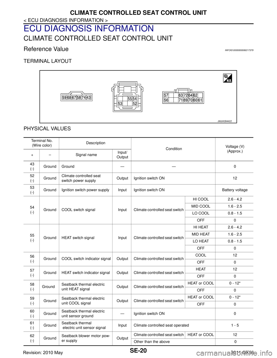
Reference ValueINFOID:0000000006217379
TERMINAL LAYOUT
PHYSICAL VALUES
JMJIA3944ZZ
Te r m i n a l N o .(Wire color) Description
ConditionVoltage (V)
(Approx.)
+ – Signal name Input/
Output
43 (-) Ground Ground — — 0
52 (-) Ground
Climate controlled seat
switch power supply Output Ignition switch ON 12
53 (-) Ground Ignition switch power supply Input Ignition switch ON Battery voltage
54 (-) Ground COOL switch signal Input Climate controlled seat switch HI COOL 2.6 - 4.2
MID COOL 1.6 - 2.5 LO COOL 0.8 - 1.5 OFF 0
55 (-) Ground HEAT switch signal Input Climate controlled seat switch HI HEAT 2.6 - 4.2
MID HEAT 1.6 - 2.5 LO HEAT 0.8 - 1.5 OFF 0
56 (-) Ground COOL switch indicator signal Output Climate controlled seat switch COOL 12
OFF 0
57 (-) Ground HEAT switch indicator signal Output Climate controlled seat switch HEAT 12
OFF 0
58 (-) Ground
Seatback thermal electric
unit HEAT signal Output Climate controlled seat switch HEAT or COOL 0 - 12*
OFF 0
59 (-) Ground
Seatback thermal electric
unit COOL signal Output Climate controlled seat switch HEAT or COOL 0 - 12*
OFF 0
60 (-) Ground Seatback thermal electric
unit sensor ground
— Ignition switch ON 0
61 (-) Ground
Seatback thermal
electric unit sensor signal Input Climate controlled seat operated 1 - 5
62 (-) Ground Seatback blower motor pow-
er supply
OutputClimate controlled seat switch HEAT or COOL 12
Other than the above 0
Revision: 2010 May2011 QX56
Page 4480 of 5598

CLIMATE CONTROLLED SEAT CONTROL UNITSE-21
< ECU DIAGNOSIS INFORMATION >
C
DE
F
G H
I
K L
M A
B
SE
N
O P*:It changes between 12 and 0 V
NOTE:
Measure the value on the condition that the battery voltage is 14 V
Wait 1 minute or more after thermal electric unit is activated, and then start the measurement
Fail-safeINFOID:0000000006217380
Climate controlled seat control unit equips fail-safe function.
When a malfunction occurs in the systems shown below , climate controlled seat control unit stops output.
63
(-) Ground Seatback blower motor
speed control signal Output Climate controlled seat switch HEAT 5.5 - 8
HI COOL 11.2
MID COOL 8
LO COOL 6.5
64 (-) Ground Blower motor ground — — 0
67 (-) Ground Seat cushion thermal electric
unit HEAT signal
Output Climate controlled seat switch HEAT or COOL 0 - 12*
OFF 0
68 (-) Ground Seat cushion thermal electric
unit COOL signal
Output Climate controlled seat switch HEAT or COOL 0 - 12*
OFF 0
69 (-) Ground Seat cushion thermal electric
unit sensor ground — Ignition switch ON 0
70 (-) Ground Seat cushion thermal electric
unit sensor signal
Input Climate controlled seat operated 1 - 5
71 (-) Ground Seat cushion blower motor
power supply OutputClimate controlled seat switch HEAT or COOL 12
Other than the above 0
72 (-) Ground seat cushion blower motor
speed control signal Output Climate controlled seat switch HEAT 5.5 - 8
HI COOL 9.2
MID COOL 8
LO COOL 6.5
74 (-) Ground Ignition switch power supply Input Ignition switch ON Battery voltage
Terminal No.
(Wire color) Description
ConditionVoltage (V)
(Approx.)
+ – Signal name Input/
Output
Revision: 2010 May2011 QX56
Page 4482 of 5598

CLIMATE CONTROLLED SEAT CONTROL UNITSE-23
< ECU DIAGNOSIS INFORMATION >
C
DE
F
G H
I
K L
M A
B
SE
N
O P
*: System voltage is the voltage between the climate controlled seat control unit power source and ground.
NOTE:
When the ignition status changes to OFF during the fail-safe mode, the control unit shall enter the OFF condition. If the ignit ion is turned
ON, the system shall return to the standby mode. If the system en ters in the fail-safe mode again after performing ignition cycle, start the
diagnosis. HEAT or COOL switch input out of the specified range
During the standby mode, heating or cooling states, if the rotary switch
input is less than 6% of the vehicle battery voltage, it stops all output and
enters the system OFF condition
When the switch input returns to a value within the specified range, the system recovers automatically
System voltage out of range If the system voltage at the climate controlled seat control unit falls out-
side of the 8.5 to 16.5 V operating range, it stops all output after a 500ms
time period.
When the system voltage returns to the normal operating range (10.5-
15.5V with a 500ms hysteresis), the system recovers automatically.
Malfunction Malfunctioning condition
Revision: 2010 May2011 QX56
Page 4526 of 5598

POWER SUPPLY AND GROUND CIRCUITSE-67
< DTC/CIRCUIT DIAGNOSIS >
C
DE
F
G H
I
K L
M A
B
SE
N
O P
DTC/CIRCUIT DIAGNOSIS
POWER SUPPLY AND GROUND CIRCUIT
CLIMATE CONTROLLED SEAT CONTROL UNIT
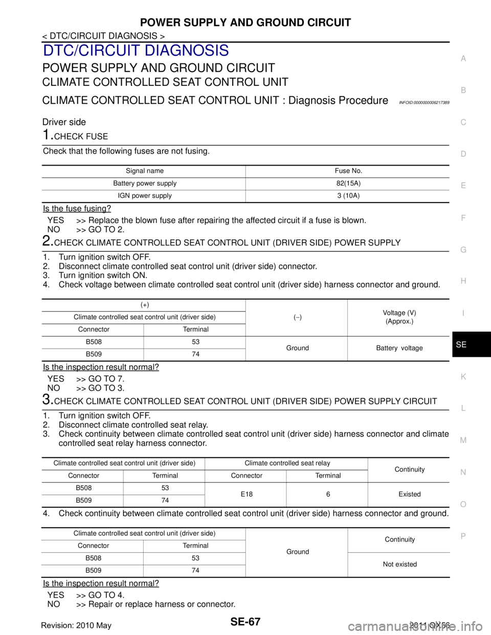
CLIMATE CONTROLLED SEAT CONT ROL UNIT : Diagnosis ProcedureINFOID:0000000006217389
Driver side
1.CHECK FUSE
Check that the following fuses are not fusing.
Is the fuse fusing?
YES >> Replace the blown fuse after repairing the affected circuit if a fuse is blown.
NO >> GO TO 2.
2.CHECK CLIMATE CONTROLLED SEAT CONTRO L UNIT (DRIVER SIDE) POWER SUPPLY
1. Turn ignition switch OFF.
2. Disconnect climate controlled seat control unit (driver side) connector.
3. Turn ignition switch ON.
4. Check voltage between climate controlled seat c ontrol unit (driver side) harness connector and ground.
Is the inspection result normal?
YES >> GO TO 7.
NO >> GO TO 3.
3.CHECK CLIMATE CONTROLLED SEAT CONTROL UNI T (DRIVER SIDE) POWER SUPPLY CIRCUIT
1. Turn ignition switch OFF.
2. Disconnect climate controlled seat relay.
3. Check continuity between climate controlled seat control unit (driver side) harness connector and climate
controlled seat relay harness connector.
4. Check continuity between climate controlled seat control unit (driver side) harness connector and ground.
Is the inspection result normal?
YES >> GO TO 4.
NO >> Repair or replace harness or connector.
Signal name Fuse No.
Battery power supply 82(15A) IGN power supply 3 (10A)
(+) (− ) Voltage (V)
(Approx.)
Climate controlled seat co
ntrol unit (driver side)
Connector Terminal B508 53 Ground Battery voltage
B509 74
Climate controlled seat control unit (dri ver side) Climate controlled seat relay
Continuity
Connector Terminal Connector Terminal
B508 53 E18 6 Existed
B509 74
Climate controlled seat co ntrol unit (driver side)
GroundContinuity
Connector Terminal
B508 53 Not existed
B509 74
Revision: 2010 May2011 QX56
Page 4527 of 5598

SE-68
< DTC/CIRCUIT DIAGNOSIS >
POWER SUPPLY AND GROUND CIRCUIT
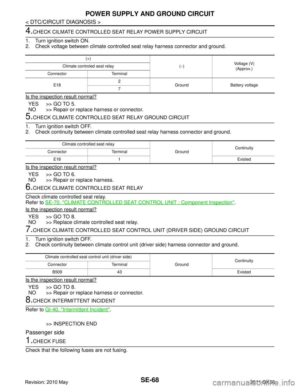
4.CHECK CILMATE CONTROLLED SEAT RELAY POWER SUPPLY CIRCUIT
1. Turn ignition switch ON.
2. Check voltage between climate controlled seat relay harness connector and ground.
Is the inspection result normal?
YES >> GO TO 5.
NO >> Repair or replace harness or connector.
5.CHECK CLIMATE CONTROLLED SEAT RELAY GROUND CIRCUIT
1. Turn ignition switch OFF.
2. Check continuity between climate cont rolled seat relay harness connector and ground.
Is the inspection result normal?
YES >> GO TO 6.
NO >> Repair or replace harness.
6.CHECK CLIMATE CONTROLLED SEAT RELAY
Check climate controlled seat relay.
Refer to SE-70, "
CLIMATE CONTROLLED SEAT CONTROL UNIT : Component Inspection".
Is the inspection result normal?
YES >> GO TO 8.
NO >> Replace climate controlled seat relay.
7.CHECK CLIMATE CONTROLLED SEAT CONTRO L UNIT (DRIVER SIDE) GROUND CIRCUIT
1. Turn ignition switch OFF.
2. Check continuity between climate contro l unit (driver side) harness connector and ground.
Is the inspection result normal?
YES >> GO TO 8.
NO >> Repair or replace harness or connector.
8.CHECK INTERMITTENT INCIDENT
Refer to GI-40, "
Intermittent Incident".
>> INSPECTION END
Passenger side
1.CHECK FUSE
Check that the following fuses are not fusing.
(+)
(− ) Voltage (V)
(Approx.)
Climate controled seat relay
Connector Terminal
E18 2
Ground Battery voltage
7
Climate controlled seat relay
GroundContinuity
Connector Terminal
E18 1 Existed
Climate controlled seat co ntrol unit (driver side)
GroundContinuity
Connector Terminal
B509 43 Existed
Revision: 2010 May2011 QX56