2011 INFINITI QX56 ground
[x] Cancel search: groundPage 4545 of 5598
SE-86
< DTC/CIRCUIT DIAGNOSIS >
CLIMATE CONTROLLED SEAT CUSHION BLOWER MOTOR
CLIMATE CONTROLLED SEAT CUSHION BLOWER MOTOR
Component Function CheckINFOID:0000000006217406
1.CHECK CLIMATE CONTROLLED SEAT CUSHION BLOWER MOTOR FUNCTION
When turning the climate controlled seat switch to the HEAT or COOL mode position, check that the climate
controlled seat cushion blower is operated in each specific mode.
Is the inspection result normal?
YES >> Climate controlled seat cushion blower motor is OK.
NO >> Refer to SE-86, "
Diagnosis Procedure".
Diagnosis ProcedureINFOID:0000000006217407
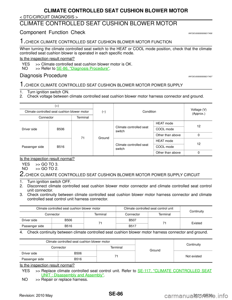
1.CHECK CLIMATE CONTROLLED SEAT CUSHION BLOWER MOTOR POWER SUPPLY
1. Turn ignition switch ON.
2. Check voltage between climate controlled seat cushion blower motor harness connector and ground.
Is the inspection result normal?
YES >> GO TO 3.
NO >> GO TO 2.
2.CHECK CLIMATE CONTROLLED SEAT CUSHION BLOWER MOTOR POWER SUPPLY CIRCUIT
1. Turn ignition switch OFF.
2. Disconnect climate controlled seat cushion blower motor connector and climate controlled seat control
unit connector.
3. Check continuity between climate controlled seat cushion blower motor harness connector and climate
controlled seat control unit harness connector.
4. Check continuity between climate controlled s eat cushion blower motor harness connector and ground.
Is the inspection result normal?
YES >> Replace climate controlled seat control unit. Refer to SE-117, "CLIMATE CONTROLLED SEAT
UNIT : Disassembly and Assembly".
NO >> Repair or replace harness.
(+)
(–) Condition Voltage (V)
(Approx.)
Climate controlled seat cushion blower motor
Connector Terminal
Driver side B506 71 GroundClimate controlled seat
switch
HEAT mode
12
COOL mode
Other than above 0
Passenger side B516 Climate controlled seat
switchHEAT mode
12
COOL mode
Other than above 0
Climate controlled seat cushion blower motor Climate controlled seat control unit Continuity
Connector Terminal Connector Terminal
Driver side B506 71B507
71 Existed
Passenger side B516 B517
Climate controlled seat cushion blower motor
GroundContinuity
Connector Terminal
Driver side B506 71 Not existed
Passenger side B516
Revision: 2010 May2011 QX56
Page 4546 of 5598
CLIMATE CONTROLLED SEAT CUSHION BLOWER MOTORSE-87
< DTC/CIRCUIT DIAGNOSIS >
C
DE
F
G H
I
K L
M A
B
SE
N
O P
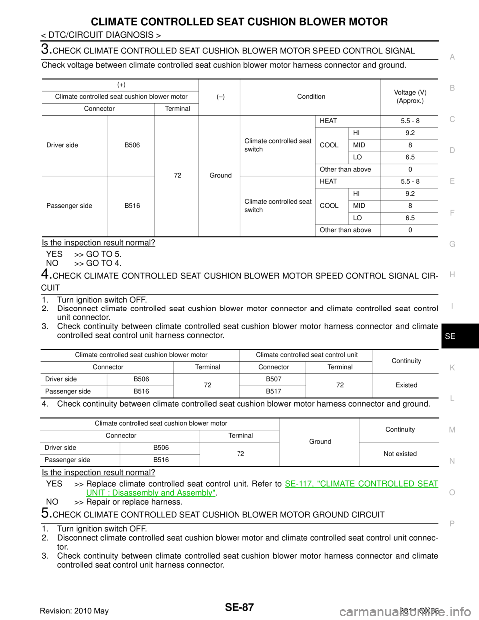
3.CHECK CLIMATE CONTROLLED SEAT CUSHION BLOWER MOTOR SPEED CONTROL SIGNAL
Check voltage between climate controlled seat cushion blower motor harness connector and ground.
Is the inspection result normal?
YES >> GO TO 5.
NO >> GO TO 4.
4.CHECK CLIMATE CONTROLLED SEAT CUSHION BL OWER MOTOR SPEED CONTROL SIGNAL CIR-
CUIT
1. Turn ignition switch OFF.
2. Disconnect climate controlled seat cushion blower motor connector and climate controlled seat control
unit connector.
3. Check continuity between climate controlled seat cushion blower motor harness connector and climate
controlled seat control unit harness connector.
4. Check continuity between climate controlled s eat cushion blower motor harness connector and ground.
Is the inspection result normal?
YES >> Replace climate controlled seat control unit. Refer to SE-117, "CLIMATE CONTROLLED SEAT
UNIT : Disassembly and Assembly".
NO >> Repair or replace harness.
5.CHECK CLIMATE CONTROLLED SEAT CUSHI ON BLOWER MOTOR GROUND CIRCUIT
1. Turn ignition switch OFF.
2. Disconnect climate controlled seat cushion blower motor and climate controlled seat control unit connec-
tor.
3. Check continuity between climate controlled seat cushion blower motor harness connector and climate
controlled seat control unit harness connector.
(+)
(–) Condition Voltage (V)
(Approx.)
Climate controlled seat cushion blower motor
Connector Terminal
Driver side B506 72 GroundClimate controlled seat
switch
HEAT 5.5 - 8
COOL
HI 9.2
MID 8
LO 6.5
Other than above 0
Passenger side B516 Climate controlled seat
switchHEAT 5.5 - 8
COOL
HI 9.2
MID 8
LO 6.5
Other than above 0
Climate controlled seat cushion blower motor Climate controlled seat control unit Continuity
Connector Terminal Connector Terminal
Driver side B506 72B507
72 Existed
Passenger side B516 B517
Climate controlled seat cushion blower motor
GroundContinuity
Connector Terminal
Driver side B506 72 Not existed
Passenger side B516
Revision: 2010 May2011 QX56
Page 4547 of 5598
SE-88
< DTC/CIRCUIT DIAGNOSIS >
CLIMATE CONTROLLED SEAT CUSHION BLOWER MOTOR
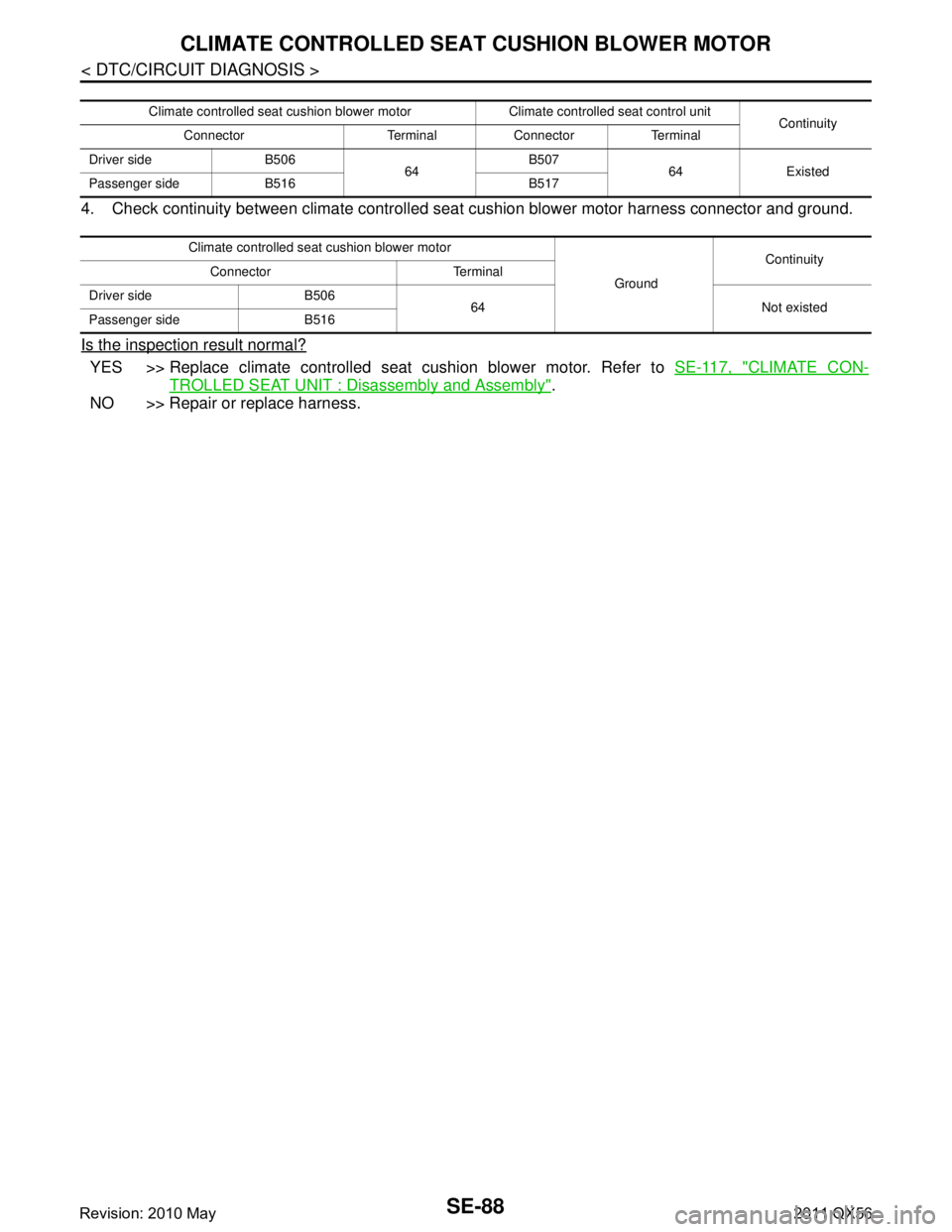
4. Check continuity between climate controlled seat cushion blower motor harness connector and ground.
Is the inspection result normal?
YES >> Replace climate controlled seat cushion blower motor. Refer to SE-117, "CLIMATE CON-
TROLLED SEAT UNIT : Disassembly and Assembly".
NO >> Repair or replace harness.
Climate controlled seat cushion blower motor Climate controlled seat control unit Continuity
Connector Terminal Connector Terminal
Driver side B506 64B507
64 Existed
Passenger side B516 B517
Climate controlled seat cushion blower motor
GroundContinuity
Connector Terminal
Driver side B506 64 Not existed
Passenger side B516
Revision: 2010 May2011 QX56
Page 4548 of 5598
CLIMATE CONTROLLED SEAT SWITCH INDICATORSE-89
< DTC/CIRCUIT DIAGNOSIS >
C
DE
F
G H
I
K L
M A
B
SE
N
O P
CLIMATE CONTROLLED SEAT SWITCH INDICATOR
Component Function CheckINFOID:0000000006217408
1.CHECK CLIMATE CONTROLLED SEA T SWITCH INDICATOR FUNCTION
Check that the related indicator lamp illuminates when c limate controlled seat switch is set to HEAT or COOL
mode.
Is the inspection result normal?
YES >> Climate controlled seat switch indicator function is OK.
NO >> Refer to SE-89, "
Diagnosis Procedure".
Diagnosis ProcedureINFOID:0000000006217409
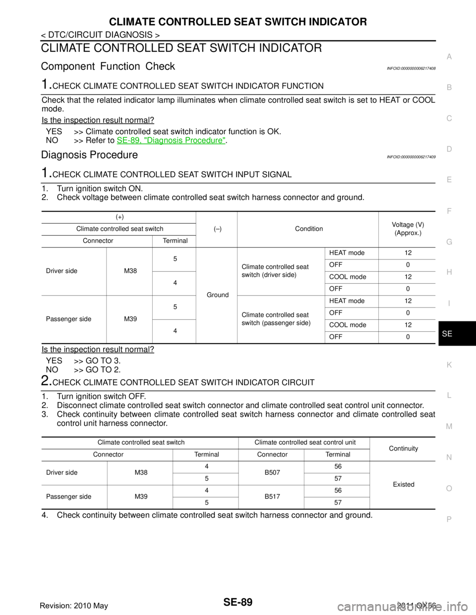
1.CHECK CLIMATE CONTROLLED SEAT SWITCH INPUT SIGNAL
1. Turn ignition switch ON.
2. Check voltage between climate controll ed seat switch harness connector and ground.
Is the inspection result normal?
YES >> GO TO 3.
NO >> GO TO 2.
2.CHECK CLIMATE CONTROLLED SEA T SWITCH INDICATOR CIRCUIT
1. Turn ignition switch OFF.
2. Disconnect climate controlled seat switch connecto r and climate controlled seat control unit connector.
3. Check continuity between climate controlled seat switch harness connector and climate controlled seat
control unit harness connector.
4. Check continuity between climate contro lled seat switch harness connector and ground.
(+)
(–) Condition Voltage (V)
(Approx.)
Climate controlled seat switch
Connector Terminal
Driver side M38 5
Ground Climate controlled seat
switch (driver side)
HEAT mode 12
OFF 0
4 COOL mode 12
OFF 0
Passenger side M39 5
Climate controlled seat
switch (passenger side) HEAT mode 12
OFF 0
4 COOL mode 12
OFF 0
Climate controlled seat switch Climate controlled seat control unit
Continuity
Connector Terminal Connector Terminal
Driver side M38 4
B507 56
Existed
557
Passenger side M39 4
B517 56
557
Revision: 2010 May2011 QX56
Page 4549 of 5598
SE-90
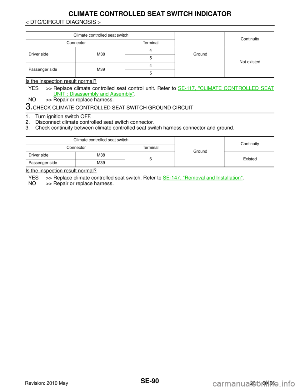
< DTC/CIRCUIT DIAGNOSIS >
CLIMATE CONTROLLED SEAT SWITCH INDICATOR
Is the inspection result normal?
YES >> Replace climate controlled seat control unit. Refer to SE-117, "CLIMATE CONTROLLED SEAT
UNIT : Disassembly and Assembly".
NO >> Repair or replace harness.
3.CHECK CLIMATE CONTROLLED SEAT SWITCH GROUND CIRCUIT
1. Turn ignition switch OFF.
2. Disconnect climate controlled seat switch connector.
3. Check continuity between climate contro lled seat switch harness connector and ground.
Is the inspection result normal?
YES >> Replace climate controlled seat switch. Refer to SE-147, "Removal and Installation".
NO >> Repair or replace harness.
Climate controlled seat switch
GroundContinuity
Connector Terminal
Driver side M38 4
Not existed
5
Passenger side M39 4
5
Climate controlled seat switch
GroundContinuity
Connector Terminal
Driver side M38 6 Existed
Passenger side M39
Revision: 2010 May2011 QX56
Page 4551 of 5598
SE-92
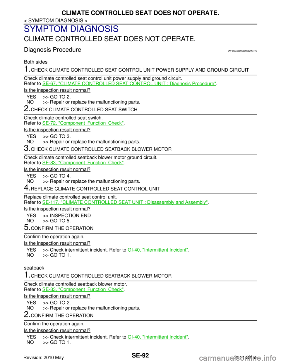
< SYMPTOM DIAGNOSIS >
CLIMATE CONTROLLED SEAT DOES NOT OPERATE.
SYMPTOM DIAGNOSIS
CLIMATE CONTROLLED SEAT DOES NOT OPERATE.
Diagnosis ProcedureINFOID:0000000006217412
Both sides
1.CHECK CLIMATE CONTROLLED SEAT CONTROL UNIT POWER SUPPLY AND GROUND CIRCUIT
Check climate controlled seat control unit power supply and ground circuit.
Refer to SE-67, "
CLIMATE CONTROLLED SEAT CONTROL UNIT : Diagnosis Procedure".
Is the inspection result normal?
YES >> GO TO 2.
NO >> Repair or replace the malfunctioning parts.
2.CHECK CLIMATE CONTROLLED SEAT SWITCH
Check climate controlled seat switch.
Refer to SE-72, "
ComponentFunctionCheck".
Is the inspection result normal?
YES >> GO TO 3.
NO >> Repair or replace the malfunctioning parts.
3.CHECK CLIMATE CONTROLLED SEATBACK BLOWER MOTOR
Check climate controlled seatback blower motor ground circuit.
Refer to SE-83, "
ComponentFunctionCheck".
Is the inspection result normal?
YES >> GO TO 4.
NO >> Repair or replace the malfunctioning parts.
4.REPLACE CLIMATE CONTROLLED SEAT CONTROL UNIT
Replace climate controlled seat control unit.
Refer to SE-117, "
CLIMATE CONTROLLED SEAT UNIT : Disassembly and Assembly".
Is the inspection result normal?
YES >> INSPECTION END
NO >> GO TO 5.
5.CONFIRM THE OPERATION
Confirm the operation again.
Is the inspection result normal?
YES >> Check intermittent incident. Refer to GI-40, "Intermittent Incident".
NO >> GO TO 1.
seatback
1.CHECK CLIMATE CONTROLLED SEATBACK BLOWER MOTOR
Check climate controlled seatback blower motor.
Refer to SE-83, "
ComponentFunctionCheck".
Is the inspection result normal?
YES >> GO TO 2.
NO >> Repair or replace the malfunctioning parts.
2.CONFIRM THE OPERATION
Confirm the operation again.
Is the inspection result normal?
YES >> Check intermittent incident. Refer to GI-40, "Intermittent Incident".
NO >> GO TO 1.
Revision: 2010 May2011 QX56
Page 4663 of 5598
![INFINITI QX56 2011 Factory Service Manual
SEC-56
< DTC/CIRCUIT DIAGNOSIS >[WITH INTELLIGENT KEY SYSTEM]
P1614 CHAIN OF IMMU-KEY
P1614 CHAIN OF IMMU-KEY
DTC LogicINFOID:0000000006226208
DTC DETECTION LOGIC
DTC CONFIRMATION PROCEDURE
1.PERFORM INFINITI QX56 2011 Factory Service Manual
SEC-56
< DTC/CIRCUIT DIAGNOSIS >[WITH INTELLIGENT KEY SYSTEM]
P1614 CHAIN OF IMMU-KEY
P1614 CHAIN OF IMMU-KEY
DTC LogicINFOID:0000000006226208
DTC DETECTION LOGIC
DTC CONFIRMATION PROCEDURE
1.PERFORM](/manual-img/42/57033/w960_57033-4662.png)
SEC-56
< DTC/CIRCUIT DIAGNOSIS >[WITH INTELLIGENT KEY SYSTEM]
P1614 CHAIN OF IMMU-KEY
P1614 CHAIN OF IMMU-KEY
DTC LogicINFOID:0000000006226208
DTC DETECTION LOGIC
DTC CONFIRMATION PROCEDURE
1.PERFORM DTC CONFIRMATION PROCEDURE 1
1. Contact Intelligent Key backside to push-button ignition switch.
2. Check DTC in “Self Diagnostic Result” mode of “ENGINE” using CONSULT-III.
Is DTC detected?
YES >> Go to SEC-56, "Diagnosis Procedure".
NO >> GO TO 2.
2.PERFORM DTC CONFIRMATION PROCEDURE 2
1. Press the push-button ignition switch.
2. Check DTC in “Self Diagnostic Result” mode of “ENGINE” using CONSULT-III.
Is DTC detected?
YES >> Go to SEC-56, "Diagnosis Procedure".
NO >> INSPECTION END
Diagnosis ProcedureINFOID:0000000006226209
1.CHECK FUSE
1. Turn ignition switch OFF.
2. Check that the following fuse in IPDM E/R is not blown.
Is the fuse fusing?
YES >> Replace the blown fuse after repairing the cause of blowing.
NO >> GO TO 2.
2.CHECK NATS ANTENNA AMP. POWER SUPPLY
1. Disconnect NATS antenna amp. connector.
2. Check voltage between NATS antenna amp. harness connector and ground.
Is the inspection result normal?
YES >> GO TO 4.
NO >> GO TO 3.
3.CHECK NATS ANTENNA AMP. POWER SUPPLY CIRCUIT
1. Disconnect IPDM E/R connector.
2. Check continuity between IPDM E/R har ness connector and NATS antenna amp. connector.
DTC No. Trouble diagnosis name DTC detecting condition Possible cause
P1614 CHAIN OF IMMU-KEY Inactive communication between NATS
antenna amp. and BCM Harness or connectors
(NATS antenna amp. circuit is open or
shorted.)
NATS antenna amp.
IPDM E/R
Signal name Fuse No.
Battery power supply 43
(+) (–)Voltage (V)
(Approx.)
NATS antenna amp.
Connector Terminal M26 1 Ground Battery voltage
Revision: 2010 May2011 QX56
Page 4664 of 5598
![INFINITI QX56 2011 Factory Service Manual
P1614 CHAIN OF IMMU-KEYSEC-57
< DTC/CIRCUIT DIAGNOSIS > [WITH INTELLIGENT KEY SYSTEM]
C
D
E
F
G H
I
J
L
M A
B
SEC
N
O P
3. Check continuity between IPDM E/R harness connector and ground.
Is the inspe INFINITI QX56 2011 Factory Service Manual
P1614 CHAIN OF IMMU-KEYSEC-57
< DTC/CIRCUIT DIAGNOSIS > [WITH INTELLIGENT KEY SYSTEM]
C
D
E
F
G H
I
J
L
M A
B
SEC
N
O P
3. Check continuity between IPDM E/R harness connector and ground.
Is the inspe](/manual-img/42/57033/w960_57033-4663.png)
P1614 CHAIN OF IMMU-KEYSEC-57
< DTC/CIRCUIT DIAGNOSIS > [WITH INTELLIGENT KEY SYSTEM]
C
D
E
F
G H
I
J
L
M A
B
SEC
N
O P
3. Check continuity between IPDM E/R harness connector and ground.
Is the inspection result normal?
YES >> Replace IPDM E/R. Refer to PCS-32, "Removal and Installation".
NO >> Repair or replace harness.
4.CHECK NATS ANTENNA AMP. OUTPUT SIGNAL 1
1. Connect NATS antenna amp. connector.
2. Disconnect BCM connector.
3. Check voltage between BCM harness connector and ground.
Is the inspection result normal?
YES >> GO TO 6.
NO >> GO TO 5.
5.CHECK NATS ANTENNA AMP. OUTPUT SIGNAL CIRCUIT 1
1. Disconnect NATS antenna amp. connector.
2. Check continuity between BCM harness connector and NATS antenna amp. connector.
3. Check continuity between BCM harness connector and ground.
Is the inspection result normal?
YES >> Replace NATS antenna amp. Refer to SEC-155, "Removal and Installation".
NO >> Repair or replace harness.
6.CHECK NATS ANTENNA AMP. COMMUNICATION SIGNAL 1
1. Connect BCM connector.
2. Check voltage between BCM harness connector and ground using analog tester.
Is the inspection result normal?
IPDM E/R NATS antenna amp. Continuity
Connector Terminal Connector Terminal
E14 42 M26 1 Existed
IPDM E/R GroundContinuity
Connector Terminal
E14 42 Not existed
(+) (–)Voltage (V)
(Approx.)
BCM
Connector Terminal M68 21 Ground 12
BCM NATS antenna amp. Continuity
Connector Terminal Connector Terminal
M6821M26 2Existed
BCM GroundContinuity
Connector Terminal
M68 21 Not existed
(+) (–) Condition Voltage (V)
(Approx.)
BCM
Connector Terminal
M68 21 Ground Contact Intelligent Key backside to
push-button ignition switch, then turn
ignition switch ON.Just after pressing push-button ignition
switch, pointer of analog tester should
move.
Revision: 2010 May2011 QX56