2011 INFINITI QX56 sensor
[x] Cancel search: sensorPage 3029 of 5598
INSPECTION AND ADJUSTMENTGI-65
< BASIC INSPECTION >
C
DE
F
G H
I
J
K L
M B
GI
N
O PINSPECTION AND ADJUSTMENT
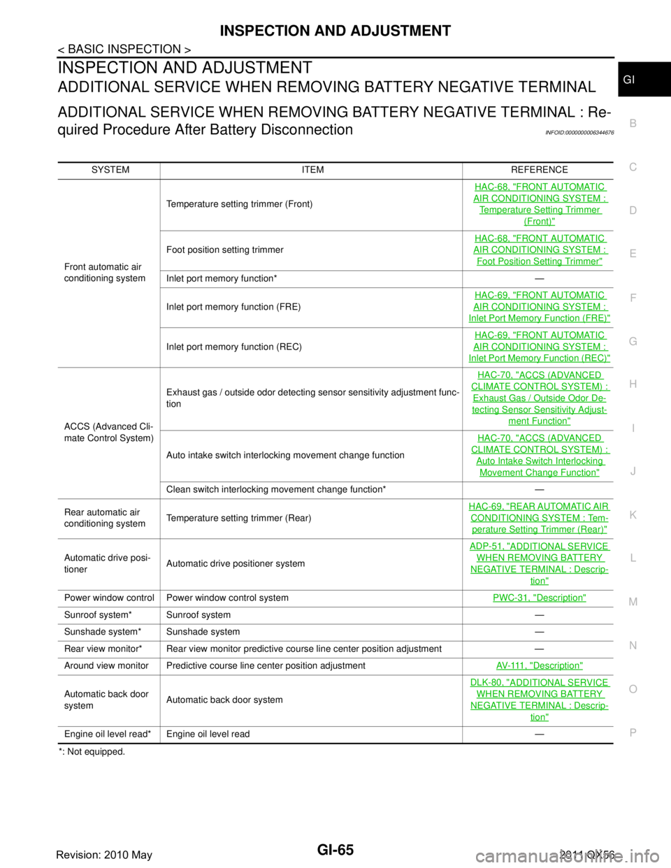
ADDITIONAL SERVICE WHEN REMOVING BATTERY NEGATIVE TERMINAL
ADDITIONAL SERVICE WHEN REMOVING BATTERY NEGATIVE TERMINAL : Re-
quired Procedure After Battery Disconnection
INFOID:0000000006344676
*: Not equipped. SYSTEM ITEM REFERENCE
Front automatic air
conditioning system Temperature setting trimmer (Front)
HAC-68, "
FRONT AUTOMATIC
AIR CONDITIONING SYSTEM :
Temperature Setting Trimmer
(Front)"
Foot position setting trimmer
HAC-68, "
FRONT AUTOMATIC
AIR CONDITIONING SYSTEM :
Foot Position Setting Trimmer"
Inlet port memory function* —
Inlet port memory function (FRE)
HAC-69, "
FRONT AUTOMATIC
AIR CONDITIONING SYSTEM :
Inlet Port Memory
Function (FRE)"
Inlet port memory function (REC) HAC-69, "
FRONT AUTOMATIC
AIR CONDITIONING SYSTEM :
Inlet Port Memory Function (REC)"
ACCS (Advanced Cli-
mate Control System)Exhaust gas / outside odor detecting sensor sensitivity adjustment func-
tion
HAC-70, "
ACCS (ADVANCED
CLIMATE CONTROL SYSTEM) :
Exhaust Gas / Outside Odor De-
tecting Sensor Sensitivity Adjust-
ment Function"
Auto intake switch interlocking movement change function
HAC-70, "
ACCS (ADVANCED
CLIMATE CONTROL SYSTEM) :
Auto Intake Switch Interlocking
Movement Change Function"
Clean switch interlocking movement change function* —
Rear automatic air
conditioning system Temperature setting trimmer (Rear) HAC-69, "
REAR AUTOMATIC AIR
CONDITIONING SYSTEM : Tem-
perature Setting
Trimmer (Rear)"
Automatic drive posi-
tioner Automatic drive positioner system ADP-51, "
ADDITIONAL SERVICE
WHEN REMOVING BATTERY
NEGATIVE TERMINAL : Descrip-
tion"
Power window control Power window control system
PWC-31, "Description"
Sunroof system* Sunroof system —
Sunshade system* Sunshade system —
Rear view monitor* Rear view monitor predictive course line center position adjustment —
Around view monitor Predictive course line center position adjustment AV- 111 , "
Description"
Automatic back door
systemAutomatic back door system DLK-80, "
ADDITIONAL SERVICE
WHEN REMOVING BATTERY
NEGATIVE TERMINAL : Descrip-
tion"
Engine oil level read* Engine oil level read —
Revision: 2010 May2011 QX56
Page 3031 of 5598
GW-2
< PRECAUTION >
PRECAUTIONS
PRECAUTION
PRECAUTIONS
Precaution for Supplemental Restraint System (SRS) "AIR BAG" and "SEAT BELT
PRE-TENSIONER"
INFOID:0000000006257243
The Supplemental Restraint System such as “A IR BAG” and “SEAT BELT PRE-TENSIONER”, used along
with a front seat belt, helps to reduce the risk or severi ty of injury to the driver and front passenger for certain
types of collision. This system includes seat belt switch inputs and dual stage front air bag modules. The SRS
system uses the seat belt switches to determine the front air bag deployment, and may only deploy one front
air bag, depending on the severity of a collision and w hether the front occupants are belted or unbelted.
Information necessary to service the system safely is included in the “SRS AIR BAG” and “SEAT BELT” of this
Service Manual.
WARNING:
• To avoid rendering the SRS inopera tive, which could increase the risk of personal injury or death in
the event of a collision that would result in air bag inflation, all maintenance must be performed by
an authorized NISS AN/INFINITI dealer.
Improper maintenance, including in correct removal and installation of the SRS, can lead to personal
injury caused by unintent ional activation of the system. For re moval of Spiral Cable and Air Bag
Module, see the “SRS AIR BAG”.
Do not use electrical test equipmen t on any circuit related to the SRS unless instructed to in this
Service Manual. SRS wiring harnesses can be identi fied by yellow and/or orange harnesses or har-
ness connectors.
PRECAUTIONS WHEN USING POWER TOOLS (AIR OR ELECTRIC) AND HAMMERS
WARNING:
When working near the Air Bag Diagnosis Sensor Unit or other Air Bag System sensors with the ignition ON or engine running, DO NOT use air or electric power tools or strike near the sensor(s)
with a hammer. Heavy vibration could activate the sensor(s) and deploy the air bag(s), possibly
causing serious injury.
When using air or electric power tools or hammers , always switch the ignition OFF, disconnect the
battery, and wait at least 3 minu tes before performing any service.
Precaution Necessary for Steering W heel Rotation after Battery Disconnect
INFOID:0000000006257244
NOTE:
Before removing and installing any control units, first tu rn the push-button ignition switch to the LOCK posi-
tion, then disconnect bot h battery cables.
After finishing work, confirm that all control unit connectors are connected properly, then re-connect both
battery cables.
Always use CONSULT-III to perform self-diagnosis as a part of each function inspection after finishing work.
If a DTC is detected, perform trouble diagnos is according to self-diagnosis results.
For vehicle with steering lock unit, if the battery is disconnected or discharged, the steering wheel will lock and
cannot be turned.
If turning the steering wheel is required with the bat tery disconnected or discharged, follow the operation pro-
cedure below before starting the repair operation.
OPERATION PROCEDURE
1. Connect both battery cables. NOTE:
Supply power using jumper cables if battery is discharged.
2. Turn the push-button ignition switch to ACC position. (At this time, the steering lock will be released.)
3. Disconnect both battery cables. The steering lock wi ll remain released with both battery cables discon-
nected and the steering wheel can be turned.
4. Perform the necessary repair operation.
Revision: 2010 May2011 QX56
Page 3040 of 5598
WINDSHIELD GLASSGW-11
< REMOVAL AND INSTALLATION >
C
DE
F
G H
I
J
L
M A
B
GW
N
O P
REMOVAL AND INSTALLATION
WINDSHIELD GLASS
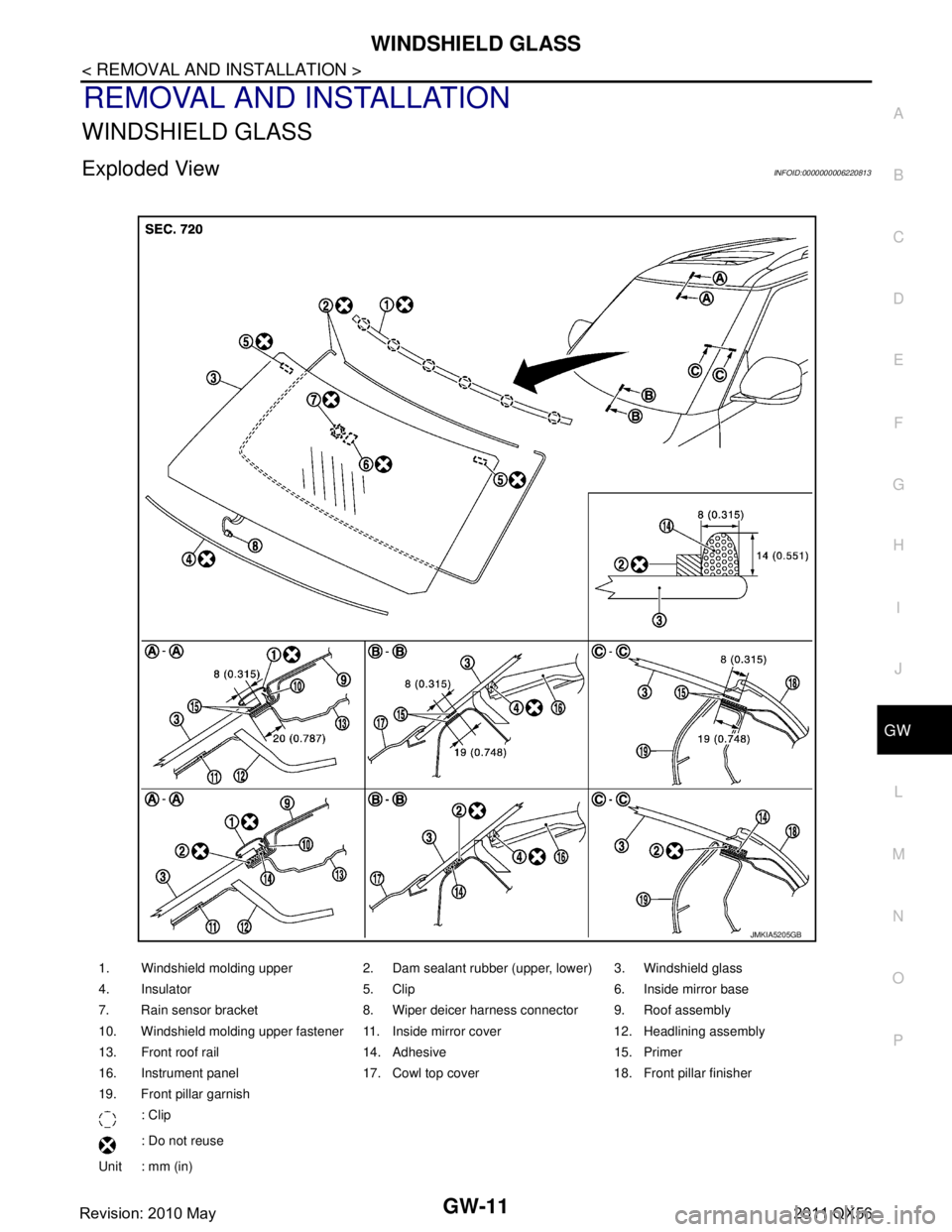
Exploded ViewINFOID:0000000006220813
1. Windshield molding upper 2. Dam sealant rubber (upper, lower) 3. Windshield glass
4. Insulator 5. Clip 6. Inside mirror base
7. Rain sensor bracket 8. Wiper deicer harness connector 9. Roof assembly
10. Windshield molding upper fastener 11. Inside mirror cover 12. Headlining assembly
13. Front roof rail 14. Adhesive 15. Primer
16. Instrument panel 17. Cowl top cover 18. Front pillar finisher
19. Front pillar garnish : Clip
: Do not reuse
Unit : mm (in)
JMKIA5205GB
Revision: 2010 May2011 QX56
Page 3041 of 5598
GW-12
< REMOVAL AND INSTALLATION >
WINDSHIELD GLASS
Removal and Installation
INFOID:0000000006220814
REMOVAL
1. Remove front pillar garnish (LH and RH). Refer to INT-14, "Removal and Installation".
2. Remove partially headlining (front edge). Refer to INT-29, "
Removal and Installation".
3. Disconnect inside mirror harness connector.
4. Remove rain sensor cover and then disconnect rain sensor harness connector. Refer to WW-72,
"Removal and Installation".
5. Remove drip molding. Refer to EXT-43, "
Removal and Installation".
6. Remove windshield molding upper using pliers. Refer to GW-11, "
Exploded View".
7. Remove front wiper arm (LH and RH). Refer to WW-66, "
Removal and Installation".
8. Remove cowl top cover. Refer to EXT-21, "
Removal and Installation".
9. Remove front fender cover (LH and RH). Refer to EXT-21, "
Exploded View".
10. Disconnect wiper deicer harness connector (with wiper deicer).
11. Remove front pillar finisher (LH and RH). Refer to EXT-40, "
Removal and Installation".
12. Apply protective tape around the windshield glas s to protect the painted surface from damage.
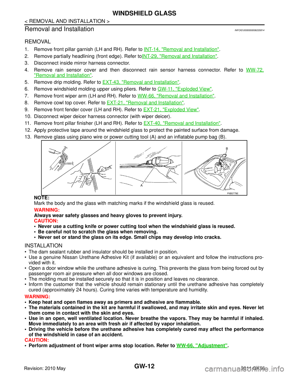
13. Remove glass using piano wire or power cutting tool (A) and an inflatable pump bag (B).
NOTE:
Mark the body and the glass with matching ma rks if the windshield glass is reused.
WARNING:
Always wear safety glasses and heavy gloves to prevent injury.
CAUTION:
Never use a cutting knife or power cutting tool when the windshield glass is reused.
Be careful not to scratch the glass when removing.
Never set or stand the glass on its edge. Small chips may develop into cracks.
INSTALLATION
The dam sealant rubber and insulator should be installed in position.
Use a genuine Nissan Urethane Adhesive Kit (if available) or an equivalent and follow the instructions pro- vided with it.
Open a door window while the urethane adhesive is curing. This prevents the glass from being forced out by
passenger room air pressure when all door windows are closed.
The molding must be installed securely so that it is in position and leaves no clearance.
Inform the customer that the vehicle should rema in stationary until the urethane adhesive has completely
cured (approximately 24 hours). Curing time varies with temperature and humidity.
WARNING:
Keep heat and open flames away as primers and adhesive are flammable.
The materials contained in the ki t are harmful if swallowed, and may irritate skin and eyes. Never let
them come in contact with the skin and eyes.
Use in an open, well ventilated location. Never br eathe the vapors. They may be harmful if inhaled.
Move immediately to an area with fresh air if affected by vapor inhalation.
Driving the vehicle before the urethane adhesive has completely cured may affect the performance
of the windshield in case of an accident.
CAUTION:
Perform adjustment of front wiper arms stop location. Refer to WW-66, "
Adjustment".
PIIB5779E
Revision: 2010 May2011 QX56
Page 3058 of 5598

HA-2
HIGH-PRESSURE PIPE : Removal and Installa-
tion ....................................................................... ...
35
LOW-PRESSURE PIPE ......................................... ...36
LOW-PRESSURE PIPE : Removal and Installa-
tion ..........................................................................
36
REAR COOLER PIPE ............................................ ...37
REAR COOLER PIPE : Removal and Installation ...37
CONDENSER ................................................. ...38
Exploded View ..................................................... ...38
CONDENSER ......................................................... ...38
CONDENSER : Removal and Installation ..............38
LIQUID TANK ......................................................... ...39
LIQUID TANK : Removal and Installation ...............39
REFRIGERANT PRESSURE SENSOR ....................39
REFRIGERANT PRESSURE SENSOR : Remov-
al and Installation ................................................. ...
39
A/C UNIT ASSEMBLY .................................... ...41
Exploded View ..................................................... ...41
HEATER & COOLING UNIT ASSEMBLY ................42
HEATER & COOLING UNIT ASSEMBLY : Re-
moval and Installation .......................................... ...
42
EVAPORATOR ...................................................... ...43
EVAPORATOR : Removal and Installation ............43
HEATER CORE ...................................................... ...44
HEATER CORE : Removal and Installation ...........44
EXPANSION VALVE .............................................. ...44
EXPANSION VALVE : Removal and Installation ....44
REAR A/C UNIT ................................................46
Exploded View ..................................................... ...46
REAR A/C UNIT ASSEMBLY ...................................47
REAR A/C UNIT ASSEMBLY : Removal and In-
stallation ............................................................... ...
47
EVAPORATOR ....................................................... ...48
EVAPORATOR : Removal and Installation .............48
EVAPORATOR PIPE ASSEMBLY ........................ ...48
EVAPORATOR PIPE ASSEMBLY : Removal and
Installation ...............................................................
48
HEATER CORE ...................................................... ...48
HEATER CORE : Removal and Installation ............48
EXPANSION VALVE .............................................. ...49
EXPANSION VALVE : Removal and Installation ....49
SERVICE DATA AND SPECIFICATIONS
(SDS) .......... ................................................
50
SERVICE DATA AND SPECIFICATIONS
(SDS) .............................................................. ...
50
Compressor ......................................................... ...50
Lubricant .................................................................50
Refrigerant ..............................................................50
Engine Idling Speed ................................................50
Belt Tension ............................................................50
Revision: 2010 May2011 QX56
Page 3059 of 5598
PRECAUTIONSHA-3
< PRECAUTION >
C
DE
F
G H
J
K L
M A
B
HA
N
O P
PRECAUTION
PRECAUTIONS
Precaution for Supplemental Restraint System (SRS) "AIR BAG" and "SEAT BELT
PRE-TENSIONER"
INFOID:0000000006276136
The Supplemental Restraint System such as “A IR BAG” and “SEAT BELT PRE-TENSIONER”, used along
with a front seat belt, helps to reduce the risk or severi ty of injury to the driver and front passenger for certain
types of collision. This system includes seat belt switch inputs and dual stage front air bag modules. The SRS
system uses the seat belt switches to determine the front air bag deployment, and may only deploy one front
air bag, depending on the severity of a collision and whether the front occupants are belted or unbelted.
Information necessary to service the system safely is included in the “SRS AIR BAG” and “SEAT BELT” of this
Service Manual.
WARNING:
• To avoid rendering the SRS inoper ative, which could increase the risk of personal injury or death in
the event of a collision that would result in air ba g inflation, all maintenance must be performed by
an authorized NISSAN/INFINITI dealer.
Improper maintenance, including in correct removal and installation of the SRS, can lead to personal
injury caused by unintentional act ivation of the system. For removal of Spiral Cable and Air Bag
Module, see the “SRS AIR BAG”.
Do not use electrical test equipm ent on any circuit related to the SRS unless instructed to in this
Service Manual. SRS wiring harnesses can be identi fied by yellow and/or orange harnesses or har-
ness connectors.
PRECAUTIONS WHEN USING POWER TOOLS (AIR OR ELECTRIC) AND HAMMERS
WARNING:
When working near the Air Bag Diagnosis Sensor Unit or other Air Bag System sensors with the
ignition ON or engine running, DO NOT use air or electric power tools or strike near the sensor(s)
with a hammer. Heavy vibration could activate the sensor(s) and deploy the air bag(s), possibly
causing serious injury.
When using air or electric power tools or hammers , always switch the ignition OFF, disconnect the
battery, and wait at least 3 minutes before performing any service.
Precaution Necessary for Steering Wh eel Rotation after Battery Disconnect
INFOID:0000000006276137
NOTE:
Before removing and installing any control units, first tu rn the push-button ignition switch to the LOCK posi-
tion, then disconnect both battery cables.
After finishing work, confirm that all control unit connectors are connected properly, then re-connect both
battery cables.
Always use CONSULT-III to perform self-diagnosis as a part of each function inspection after finishing work.
If a DTC is detected, perform trouble diagnos is according to self-diagnosis results.
For vehicle with steering lock unit, if the battery is disconnected or discharged, the steering wheel will lock and
cannot be turned.
If turning the steering wheel is required with the batte ry disconnected or discharged, follow the operation pro-
cedure below before starting the repair operation.
OPERATION PROCEDURE
1. Connect both battery cables. NOTE:
Supply power using jumper cables if battery is discharged.
2. Turn the push-button ignition switch to ACC position. (At this time, the steering lock will be released.)
3. Disconnect both battery cables. The steering lock wil l remain released with both battery cables discon-
nected and the steering wheel can be turned.
4. Perform the necessary repair operation.
Revision: 2010 May2011 QX56
Page 3061 of 5598
PRECAUTIONSHA-5
< PRECAUTION >
C
DE
F
G H
J
K L
M A
B
HA
N
O P
- Never allow lubricant (A/C System Oil Type R) to come in contact with styrene foam parts. Damage
may result.
REFRIGERANT CONNECTION
A new type refrigerant connection has been introduced to a ll refrigerant lines except the following location.
Expansion valve to evaporator
Refrigerant pressure sensor to liquid tank
WARNING:
Check that all refrigerant is discharged into the recycling equipment and the pressure in the system is
less than atmospheric pressure. Then gradually loo sen the discharge side hose fitting and remove it.
CAUTION:
Observe the following when replacing or cleaning refrigerant cycle components.
Store it in the same way at it is when mounted on the car when the compressor is removed. Failure
to do so will cause lubricant to enter the low-pressure chamber.
Use always a torque wrench and a b ack-up wrench when connecting tubes.
Plug immediately all openings to prevent entry of dust and mois ture after disconnecting tubes.
Connect the pipes at the final stag e of the operation when installing an air conditioner in the vehicle.
Never remove the seal caps of pipes and other compon ents until just before required for connection.
Allow components stored in cool areas to warm to working area temperature before removing seal
caps. This prevents condensation from forming inside A/C components.
Remove thoroughly moisture from the refriger ation system before charging the refrigerant.
Replace always used O-rings.
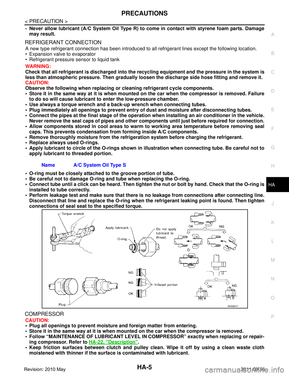
Apply lubricant to circle of th e O-rings shown in illustration when connecting tube. Be careful not to
apply lubricant to threaded portion.
O-ring must be closely attached to the groove portion of tube.
Be careful not to damage O-ring and tube when replacing the O-ring.
Connect tube until a click can be heard. Then tighten the nut or bolt by hand. Check that the O-ring is
installed to tube correctly.
Perform leakage test and make sure that there is no leakage from connections after connecting line.
Disconnect that line and replace the O-ring when the refrigerant leaking point is found. Then tighten
connections of seal seat to the specified torque.
COMPRESSOR
CAUTION:
Plug all openings to prevent moisture and foreign matter from entering.
Store it in the same way at it is when moun ted on the car when the compressor is removed.
Follow “MAINTENANCE OF LUBRICANT LEVEL IN CO MPRESSOR” exactly when replacing or repair-
ing compressor. Refer to HA-22, "
Description".
Keep friction surfaces between clutch and pulley cl ean. Wipe it off by using a clean waste cloth
moistened with thinner if the surface is contaminated with lubricant.
Name A/C System Oil Type S
RHA861F
Revision: 2010 May2011 QX56
Page 3069 of 5598
COMPONENT PARTSHA-13
< SYSTEM DESCRIPTION >
C
DE
F
G H
J
K L
M A
B
HA
N
O P
SYSTEM DESCRIPTION
COMPONENT PARTS
Component Parts LocationINFOID:0000000006276144
Component DescriptionINFOID:0000000006276145
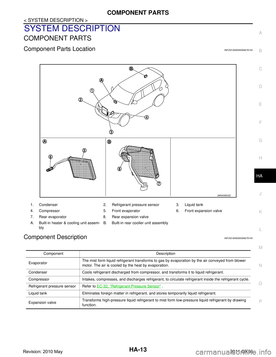
JMIIA0920ZZ
1. Condenser 2. Refrigerant pressure sensor 3. Liquid tank
4. Compressor 5. Front evaporator 6. Front expansion valve
7. Rear evaporator 8. Rear expansion valve
A. Built-in heater & cooling unit assem- bly B. Built-in rear coolier unit assembly
Component Description
Evaporator The mist form liquid refrigerant transforms to gas by evaporation by the air conveyed from blower
motor. The air is cooled by the heat by evaporation.
Condenser Cools refrigerant discharged from compressor, and transforms it to liquid refrigerant.
Compressor Intakes, compresses, and discharges refrigerant, to circulate refrigerant inside the refrigerant cycle.
Refrigerant pressure sensor Refer to EC-32, "
Refrigerant Pressure Sensor" .
Liquid tank Eliminates foreign matter in refrigerant, and stores temporarily liquid refrigerant.
Expansion valve Transforms high-pressure liquid refrigerant to mist form low-pressure liquid refrigerant by drawing
function.
Revision: 2010 May2011 QX56