2011 INFINITI QX56 sensor
[x] Cancel search: sensorPage 3071 of 5598

SYSTEMHA-15
< SYSTEM DESCRIPTION >
C
DE
F
G H
J
K L
M A
B
HA
N
O P
The refrigerant from the compressor, frows the condens er with liquid tank, the evaporator, and returns to the
compressor. The refrigerant evaporation in the evaporator is controlled by an expansion valve.
Freeze Protection
Automatic air conditioner When intake sensor detects that evaporator surface temperature is 2.5°C (37 °F) or less, A/C auto amp.
requests BCM to turn the compressor OFF.
BCM requests ECM to turn the compressor to OFF by the signal from A/C auto amp., and ECM makes A/C
relay to OFF, and stops the compressor.
REFRIGERANT SYSTEM PROTECTION
Refrigerant Pressure Sensor
The refrigerant system is protected against excessively high- or low-pressures by the refrigerant pressure
sensor, installed at the condenser exit. The refrigerant pressure sensor detects the pressure inside the
refrigerant line and sends the voltage signal to the ECM if the system pressure rises above, or falls below
the specifications.
ECM turns the A/C relay to OFF and stops the compress or when the high-pressure side detected by refriger-
ant pressure sensor is following conditions;
- Approximately 3,120 kPa (31.8 kg/cm
2, 452 psi) or more (Engine speed is less than 1,500 rpm.)
- Approximately 2,740 kPa (27.9 kg/cm
2, 397 psi) or more (Engine speed is 1,500 rpm or more.)
- Approximately 140 kPa (1.4 kg/cm
2, 20 psi) or less
Pressure Relief Valve
The refrigerant system is also protected by a pressure relief valve, located in the rear head of the compressor.
The release port on the pressure relief valve automatical ly opens and releases refrigerant into the atmosphere
when the pressure of refrigerant in the system incr eases to an unusual level [more than 3,800 kPa (38.8 kg/
cm
2, 551 psi)].
Revision: 2010 May2011 QX56
Page 3084 of 5598
HA-28
< SYMPTOM DIAGNOSIS >
REFRIGERATION SYSTEM SYMPTOMS
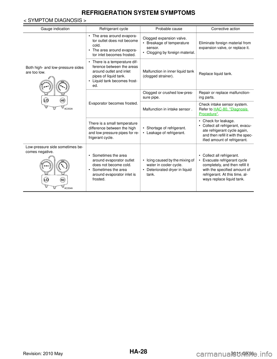
Both high- and low-pressure sides
are too low. The area around evapora-
tor outlet does not become
cold.
The area around evapora- tor inlet becomes frosted. Clogged expansion valve.
Breakage of temperature
sensor.
Clogging by foreign material. Eliminate foreign material from
expansion valve, or replace it.
There is a temperature dif- ference between the areas
around outlet and inlet
pipes of liquid tank.
Liquid tank becomes frost- ed. Malfunction in inner liquid tank
(clogged strainer).
Replace liquid tank.
Evaporator becomes frosted. Clogged or crushed low-pres-
sure pipe.
Repair or replace malfunction-
ing parts.
Malfunction in intake sensor . Check intake sensor system.
Refer to
HAC-80, "
Diagnosis
Procedure".
There is a small temperature
difference between the high
and low pressure pipes for re-
frigerant cycle. Shortage of refrigerant.
Leakage of refrigerant. Check for leakage.
Collect all refrigerant, evacu-
ate refrigerant cycle again,
and then refill it with the spec-
ified amount of refrigerant.
Low-pressure side sometimes be-
comes negative. Sometimes the area
around evaporator outlet
does not become cold.
Sometimes the area
around evaporator inlet is
frosted. Icing caused by the mixing of
water in cooler cycle.
Deteriorated dryer in liquid
tank. Collect all refrigerant.
Evacuate refrigerant cycle
completely, and then refill it
with the specified amount of
refrigerant. At this time, al-
ways replace liquid tank.
Gauge indication Refrigerant cycle Probable cause Corrective action
AC353A
AC354A
Revision: 2010 May2011 QX56
Page 3094 of 5598
HA-38
< REMOVAL AND INSTALLATION >
CONDENSER
CONDENSER
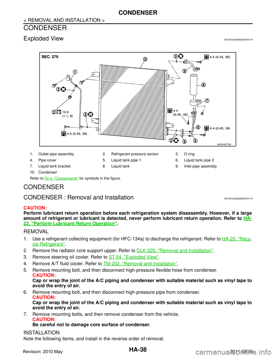
Exploded ViewINFOID:0000000006276178
CONDENSER
CONDENSER : Removal and InstallationINFOID:0000000006276179
CAUTION:
Perform lubricant return operation before each refrigeration system disassembly. However, if a large
amount of refrigerant or lubrican t is detected, never perform lubricant return operation. Refer to HA-
22, "Perform Lubricant Return Operation".
REMOVAL
1. Use a refrigerant collecting equipment (for HF C-134a) to discharge the refrigerant. Refer to HA-20, "Recy-
cle Refrigerant".
2. Remove the radiator core support upper. Refer to DLK-220, "
Removal and Installation".
3. Remove steering oil cooler. Refer to ST-54, "
Exploded View".
4. Remove A/T fluid cooler. Refer to TM-202, "
Removal and Installation".
5. Remove mounting bolt, and then disconnect high-pressure flexible hose from condenser. CAUTION:
Cap or wrap the joint of the A/C piping and conden ser with suitable material such as vinyl tape to
avoid the entry of air.
6. Remove mounting bolt, and then disconnect high-pressure pipe from condenser. CAUTION:
Cap or wrap the joint of the A/C piping and conden ser with suitable material such as vinyl tape to
avoid the entry of air.
7. Remove mounting bolts, and then remove condenser from the vehicle. CAUTION:
Be careful not to damage core surface of condenser.
INSTALLATION
Note the following items, and install in the reverse order of removal.
1. Outlet pipe assembly 2. Refrigerant pressure sensor 3. O-ring
4. Pipe cover 5. Liquid tank pipe 1 6. Liquid tank pipe 2
7. Liquid tank bracket 8. Liquid tank 9. Inlet pipe assembly
10. Condenser
Refer to GI-4, "
Components" for symbols in the figure.
JMIIA0627GB
Revision: 2010 May2011 QX56
Page 3095 of 5598
CONDENSERHA-39
< REMOVAL AND INSTALLATION >
C
DE
F
G H
J
K L
M A
B
HA
N
O P
CAUTION:
Replace O-rings with new ones. Then apply compressor oil to them when installing.
Perform lubricant adjusting procedure befo re installing new condenser. Refer to HA-22, "
Lubricant
Adjusting Procedure for Components Replacement Except Compressor".
Check for leakages when recharging refrigerant. Refer to HA-18, "
Leak Test".
LIQUID TANK
LIQUID TANK : Removal and InstallationINFOID:0000000006276180
CAUTION:
Perform lubricant return operation before each refrigeration system disassembly. However, if a large
amount of refrigerant or lubricant is detected, n ever perform lubricant return operation. Refer to HA-
22, "Perform Lubricant Return Operation".
REMOVAL
1. Use a refrigerant collecting equipment (for HF C-134a) to discharge the refrigerant. Refer to HA-20, "Recy-
cle Refrigerant".
2. Remove front bumper fascia. Refer to EXT-13, "
Removal and Installation".
3. Clean liquid tank and its surrounding area, and then remove dust and rust from liquid tank. CAUTION:
Be sure to clean carefully.
4. Remove mounting bolts, and then remove liquid tank from the condenser. CAUTION:
Cap or wrap the joint of the A/C piping and liquid tank with suitable material such as vinyl tape to
avoid the entry of air.
INSTALLATION
Install liquid tank, and then install liquid tank bracket on condenser.
CAUTION:
Check that liquid tank bracket is securely installe d at protrusion of condenser. (Check that liquid
tank bracket never move to a positio n below center of liquid tank.)
Replace O-rings of the A/ C piping with new ones. Then apply comp ressor oil to them when installing.
Perform lubricant adjusting procedure befo re installing new liquid tank. Refer to HA-22, "
Lubricant
Adjusting Procedure for Components Replacement Except Compressor".
Check for leakages when recharging refrigerant. Refer to HA-18, "
Leak Test".
REFRIGERANT PRESSURE SENSOR
REFRIGERANT PRESSURE SENSOR : Removal and InstallationINFOID:0000000006276181
CAUTION:
Perform lubricant return operation before each refrigeration system disassembly. However, if a large
amount of refrigerant or lubricant is detected, n ever perform lubricant return operation. Refer to HA-
22, "Perform Lubricant Return Operation".
REMOVAL
1. Use a refrigerant collecting equipment (for HF C-134a) to discharge the refrigerant. Refer to HA-20, "Recy-
cle Refrigerant".
2. Remove front grille. Refer to EXT-19, "
Removal and Installation".
3. Clean refrigerant pressure sensor and its surrounding area, and then remove dust and rust from refriger- ant pressure sensor.
CAUTION:
Be sure to clean carefully.
4. Disconnect refrigerant pressure sensor connector.
5. Use a adjustable wrench or other tool to hold the refrigerant pressure sensor mounting block, and then
remove the refrigerant pressure sensor from the condenser.
CAUTION:
Be careful not to damage liquid tank.
Be careful not to damage core surface of condenser.
Cap or wrap the joint of the condenser and liquid tank with suitable material such as vinyl tape to
avoid the entry of air.
Revision: 2010 May2011 QX56
Page 3098 of 5598
HA-42
< REMOVAL AND INSTALLATION >
A/C UNIT ASSEMBLY
HEATER & COOLING UNIT ASSEMBLY
HEATER & COOLING UNIT ASSEMBLY : Removal and InstallationINFOID:0000000006276183
CAUTION:
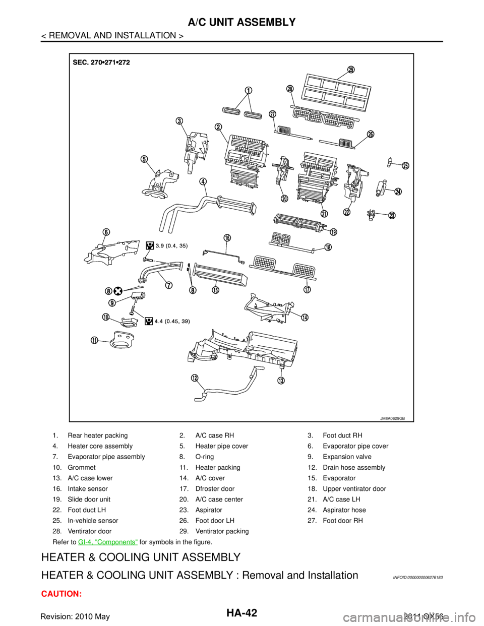
1. Rear heater packing 2. A/C case RH 3. Foot duct RH
4. Heater core assembly 5. Heater pipe cover 6. Evaporator pipe cover
7. Evaporator pipe assembly 8. O-ring 9. Expansion valve
10. Grommet 11. Heater packing 12. Drain hose assembly
13. A/C case lower 14. A/C cover 15. Evaporator
16. Intake sensor 17. Dfroster door 18. Upper ventirator door
19. Slide door unit 20. A/C case center 21. A/C case LH
22. Foot duct LH 23. Aspirator 24. Aspirator hose
25. In-vehicle sensor 26. Foot door LH 27. Foot door RH
28. Ventirator door 29. Ventirator packing
Refer to GI-4, "
Components" for symbols in the figure.
JMIIA0629GB
Revision: 2010 May2011 QX56
Page 3099 of 5598
A/C UNIT ASSEMBLYHA-43
< REMOVAL AND INSTALLATION >
C
DE
F
G H
J
K L
M A
B
HA
N
O P
Perform lubricant return operati on before each refrigeration system disassembly. However, if a large
amount of refrigerant or lubricant is detected, n ever perform lubricant return operation. Refer to HA-
22, "Perform Lubricant Return Operation".
REMOVAL
1. Use a refrigerant collecting equipment (for HF C-134a) to discharge the refrigerant. Refer to HA-20, "Recy-
cle Refrigerant". (If equipped)
2. Drain engine coolant from cooling system. Refer to CO-8, "
Draining".
3. Remove clamps, and then disconnect front heater outlet hose from heater pipe.
CAUTION:
Some coolant may spill when heater hoses are disconnected.
Close off the coolant inlet and outlet on the heater core (2 locations) with shop cloths.
4. Remove mounting bolt, and then disconnect low-pressure pipe and high-pressure pipe from expansion valve.
CAUTION:
Cap or wrap the joint of the A/C piping and expan sion valve with suitable material such as vinyl
tape to avoid the entry of air.
5. Remove instrument panel assembly. Refer to IP-14, "
Removal and Installation".
6. Remove steering column mounting bolt and nuts. Refer to ST-34, "
Removal and Installation".
7. Move steering column assembly to a position where it does not inhibit work.
8. Disconnect harness clips, harness connectors, ground bol ts and blackets from steering member, and then
move the vehicle harness to the position without hindrance for work.
9. Remove mounting nuts, and then remove instrument stay (RH and LH).
10. Remove A/C unit assembly mounting bolts.
11. Remove mounting bolts, and then remove steering member from the vehicle.
12. Disconnect drain hose from A/C unit assembly, and then remove A/C unit assembly from the vehicle.
13. Remove mounting bolts, and then disconnect heater & cooling unit and blower unitassembly.
INSTALLATION
Note the following items, and install in the reverse order of removal.
CAUTION:
Replace O-rings with new ones. Then apply compressor oil to them when installing.
Check for leakages when recharging refrigerant. Refer to HA-18, "
Leak Test".
NOTE:
Refer to CO-9, "
Refilling" when filling radiator with engine coolant.
EVAPORATOR
EVAPORATOR : Removal and InstallationINFOID:0000000006276184
REMOVAL
1. Remove heater & cooling unit assembly. Refer to HA-41, "Exploded View".
2. Remove heater core. Refer to HA-44, "
HEATER CORE : Removal and Installation".
3. Remove mounting screws, and then remove evaporator pipe cover.
4. Remove air mix door motor (RH). Refer to HAC-153, "
AIR MIX DOOR MOTOR : Removal and Installa-
tion".
5. Remove mounting screws, and then remove A/C cover.
6. Remove foot duct LH. Refer to VTL-11, "
FLOOR DUCT 1 : Removal and Installation".
7. Remove mounting screws, and then remove A/C lower case.
8. Remove intake sensor. Refer to HAC-150, "
Removal and Installation".
9. Remove evaporator assembly from heater & cooling unit assembly.
10. Remove mounting bolts, and then remove evaporator from evaporator assembly.
CAUTION:
Cap or wrap the joint of the evaporator and evaporat or pipe assembly with suitable material such as
vinyl tape to avoid the entry of air.
Revision: 2010 May2011 QX56
Page 3100 of 5598
HA-44
< REMOVAL AND INSTALLATION >
A/C UNIT ASSEMBLY
INSTALLATION
Note the following items, and install in the reverse order of removal.
CAUTION:
Replace O-rings with new ones. Then apply compressor oil to them when installing.
When install the intake sensor, set the same position before replacement.
Never rotate the bracket insertion part when removing and installing the intake sensor.
Perform lubricant adjusting procedure af ter installing new evaporator. Refer to HA-22, "
Lubricant
Adjusting Procedure for Components Replacement Except Compressor".
HEATER CORE
HEATER CORE : Removal and InstallationINFOID:0000000006276185
REMOVAL
1. Remove heater & cooling unit assembly. Refer to HA-42, "HEATER & COOLING UNIT ASSEMBLY :
Removal and Installation".
2. Remove mounting screws, and then remove heater core pipe cover.
3. Remove mode door motor. Refer to HAC-153, "
MODE DOOR MOTOR : Removal and Installation".
4. Remove main link, foot door link and foot door lever. Refer to HAC-152, "
Exploded View".
5. Remove mounting screws, and then remove foot duct (assist side). Refer to VTL-11, "
FLOOR DUCT 1 :
Removal and Installation".
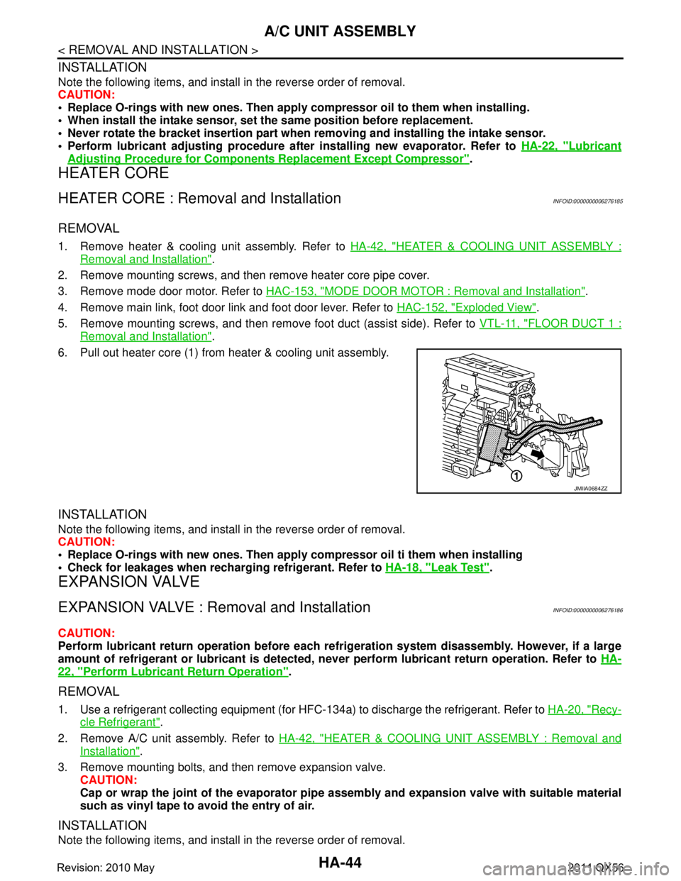
6. Pull out heater core (1) from heater & cooling unit assembly.
INSTALLATION
Note the following items, and install in the reverse order of removal.
CAUTION:
Replace O-rings with new ones. Then apply compressor oil ti them when installing
Check for leakages when recharging refrigerant. Refer to HA-18, "
Leak Test".
EXPANSION VALVE
EXPANSION VALVE : Removal and InstallationINFOID:0000000006276186
CAUTION:
Perform lubricant return operation before each refrigeration system disassembly. However, if a large
amount of refrigerant or lubrican t is detected, never perform lubricant return operation. Refer to HA-
22, "Perform Lubricant Return Operation".
REMOVAL
1. Use a refrigerant collecting equipment (for HF C-134a) to discharge the refrigerant. Refer to HA-20, "Recy-
cle Refrigerant".
2. Remove A/C unit assembly. Refer to HA-42, "
HEATER & COOLING UNIT ASSEMBLY : Removal and
Installation".
3. Remove mounting bolts, and then remove expansion valve. CAUTION:
Cap or wrap the joint of the evaporator pipe assembly and expansion valve with suitable material
such as vinyl tape to avoid the entry of air.
INSTALLATION
Note the following items, and install in the reverse order of removal.
JMIIA0684ZZ
Revision: 2010 May2011 QX56
Page 3103 of 5598

REAR A/C UNITHA-47
< REMOVAL AND INSTALLATION >
C
DE
F
G H
J
K L
M A
B
HA
N
O P
REAR A/C UNIT ASSEMBLY
REAR A/C UNIT ASSEMBLY : Removal and InstallationINFOID:0000000006276188
REMOVAL
1. Use a refrigerant collecting equipment (for HF C-134a) to discharge the refrigerant. Refer to HA-22, "Per-
form Lubricant Return Operation".
2. Drain engine coolant from cooling system. Refer to HA-22, "
Perform Lubricant Return Operation".
3. Remove rear ventilator duct upper. Refer to VTL-12, "
REAR VENTILATOR DUCT UPPER : Removal and
Installation".
4. Remove rear ventilator duct lower. Refer to VTL-12, "
REAR VENTILATOR DUCT LOWER : Removal and
Installation".
5. Remove mounting bolt, and then disconnect rear cooler unit pipe assembly from rear cooler pipe assem-
bly.
1. Rear blower harness 2. Rear blower motor 3. Rear A/C unit case RH
4. Rear evaporator pipe assembly 5. O-ring 6. Rear expantion valve assembly
7. Rear A/C cooler pipe assembly 8. Pipe bracket 9. Grommet
10. Rear cooler pipe 11. Rear heater outlet tube assembly 12. Blind cap
13. Rear heater inlet tube assembly 14. Clamp 15. Clamp
16. Shild plate 17. Bracket 18. Rear A/C unit case LH
19. Rear evapolator 20. Drain hose 21. Rear air mix door
22. Rear heater core 23. Rear heater pipe clamp 24. Rear A/C unit upper case (front)
25. Rear mode door 26. Rear A/C unit upper case (rear) 27. Air mix door harness
28. Rear intake sensor 29. Packing
Refer to GI-4, "
Components" for symbols in the figure.
JMIIA0641GB
Revision: 2010 May2011 QX56