2011 INFINITI QX56 headlamp
[x] Cancel search: headlampPage 2855 of 5598
![INFINITI QX56 2011 Factory Service Manual
SERVICE DATA AND SPECIFICATIONS (SDS)
EXL-145
< SERVICE DATA AND SPECIFICATIONS (SDS) [XENON TYPE]
C
D
E
F
G H
I
J
K
M A
B
EXL
N
O P
SERVICE DATA AND SPECIFICATIONS (SDS)
SERVICE DATA AND SPECIFICAT INFINITI QX56 2011 Factory Service Manual
SERVICE DATA AND SPECIFICATIONS (SDS)
EXL-145
< SERVICE DATA AND SPECIFICATIONS (SDS) [XENON TYPE]
C
D
E
F
G H
I
J
K
M A
B
EXL
N
O P
SERVICE DATA AND SPECIFICATIONS (SDS)
SERVICE DATA AND SPECIFICAT](/manual-img/42/57033/w960_57033-2854.png)
SERVICE DATA AND SPECIFICATIONS (SDS)
EXL-145
< SERVICE DATA AND SPECIFICATIONS (SDS) [XENON TYPE]
C
D
E
F
G H
I
J
K
M A
B
EXL
N
O P
SERVICE DATA AND SPECIFICATIONS (SDS)
SERVICE DATA AND SPECIFICATIONS (SDS)
Bulb SpecificationsINFOID:0000000006369512
Item Type Wattage (W)
Front combination lamp Headlamp (HI/LO) D2S (Xenon) 35
Front turn signal lamp WY21W (Amber) 21
Parking lamp W5W 5
Front fog lamp H8 35
Side turn signal lamp Replace as an assembly because it cannot be disassembled.
Rear combination lamp Stop lamp/Tail lamp LED —
Rear turn signal lamp WY21W 21
Back-up lamp W16W 16
Tail lamp W5W 5
License plate lamp W5W 5
High-mounted stop lamp LED —
Revision: 2010 May2011 QX56
Page 2870 of 5598

FRONT BUMPEREXT-15
< REMOVAL AND INSTALLATION >
C
DE
F
G H
I
J
L
M A
B
EXT
N
O P
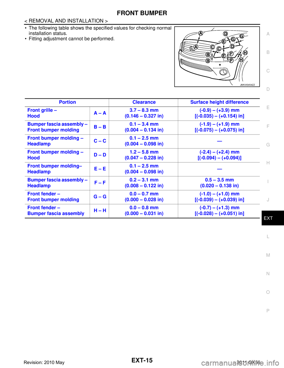
The following table shows the specified values for checking normal installation status.
Fitting adjustment cannot be performed.
JMKIA5454ZZ
Portion Clearance Surf ace height difference
Front grille –
Hood A – A3.7 – 8.3 mm
(0.146 – 0.327 in) (-0.9) – (+3.9) mm
[(-0.035) – (+0.154) in]
Bumper fascia assembly –
Front bumper molding B – B0.1 – 3.4 mm
(0.004 – 0.134 in) (-1.9) – (+1.9) mm
[(-0.075) – (+0.075) in]
Front bumper molding –
Headlamp C – C0.1 – 2.5 mm
(0.004 – 0.098 in) —
Front bumper molding –
Hood D – D1.2 – 5.8 mm
(0.047 – 0.228 in) (-2.4) – (+2.4) mm
[(-0.094) – (+0.094)]
Front bumper molding–
Headlamp E – E0.1 – 2.5 mm
(0.004 – 0.098 in) —
Bumper fascia assembly –
Headlamp F – F0.2 – 3.1 mm
(0.008 – 0.122 in) 0.5 – 3.5 mm
(0.020 – 0.138 in)
Front fender –
Front bumper molding G – G0.0 – 0.7 mm
(0.000 – 0.028 in) (-1.0) – (+1.0) mm
[(-0.039) – (+0.039) in]
Front fender –
Bumper fascia assembly H – H0.0 – 0.8 mm
(0.000 – 0.031 in) (-0.7) – (+1.3) mm
[(-0.028) – (+0.051) in]
Revision: 2010 May2011 QX56
Page 2965 of 5598

GI-1
GENERAL INFORMATION
C
DE
F
G H
I
J
K L
M B
GI
SECTION GI
N
O P
CONTENTS
GENERAL INFORMATION
HOW TO USE THIS MANU AL ......................3
HOW TO USE THIS MANUAL ....................... .....3
Description .......................................................... ......3
Terms ........................................................................3
Units ..........................................................................3
Contents ....................................................................3
Relation between Illustrations and Descriptions .......4
Components ..............................................................4
HOW TO FOLLOW TROUBLE DIAGNOSES .....6
Description ................................................................6
How to Follow Test Groups in Trouble Diagnosis ......6
Key to Symbols Signifying Measurements or Pro-
cedures ............................................................... ......
7
HOW TO READ WIRING DIAGRAMS ................9
Connector Symbols ............................................. ......9
Sample/Wiring Diagram -Example- .........................10
Connector Information .............................................12
ABBREVIATIONS .......................................... ....14
Abbreviation List .................................................. ....14
TIGHTENING TORQUE OF STANDARD
BOLTS ................................................................
19
Description .......................................................... ....19
Tightening Torque Table (New Standard Includ-
ed) ...........................................................................
19
RECOMMENDED CHEMICAL PRODUCTS
AND SEALANTS ................................................
22
Recommended Chemical Products and Sealants ....22
VEHICLE INFORMATION ............................23
IDENTIFICATION INFORMATION ................. ....23
Model Variation ................................................... ....23
Information About Identification or Model Code ......23
Dimensions .............................................................25
Wheels & Tires ........................................................25
PRECAUTION ..............................................26
PRECAUTIONS .................................................26
Description ........................................................... ....26
Precaution for Supplemental Restraint System
(SRS) "AIR BAG" and "SEAT BELT PRE-TEN-
SIONER" .................................................................
26
Precautions For Xenon Headlamp Service .............26
Precaution Necessary for Steering Wheel Rota-
tion after Battery Disconnect ...................................
27
Precaution for Procedure without Cowl Top Cover ....27
General Precautions ................................................27
Three Way Catalyst .................................................29
Multiport Fuel Injection System or Engine Control
System .....................................................................
29
Hoses ......................................................................29
Engine Oils ..............................................................30
Air Conditioning .......................................................31
Fuel ..........................................................................31
LIFTING POINT .................................................32
Pantograph Jack ......................................................32
Garage Jack and Safety Stand ................................32
2-Pole Lift ................................................................33
TOW TRUCK TOWING .....................................34
Tow Truck Towing ...................................................34
Vehicle Recovery (Freeing a Stuck Vehicle) ...........34
BASIC INSPECTION ...................................36
SERVICE INFORMATION FOR ELECTRICAL
INCIDENT ..........................................................
36
Work Flow ............................................................ ....36
Control Units and Electrical Parts ............................36
How to Check Terminal ...........................................37
Intermittent Incident .................................................40
Circuit Inspection .....................................................43
CONSULT-III/GST CHECKING SYSTEM .........48
Description ...............................................................48
CONSULT-III Function and System Application*1 ....48
Revision: 2010 May2011 QX56
Page 2990 of 5598

GI-26
< PRECAUTION >
PRECAUTIONS
PRECAUTION
PRECAUTIONS
DescriptionINFOID:0000000006280865
Observe the following precautions to ensure safe and proper servicing. These precautions are not
described in each individual section.
Precaution for Supplemental Restraint S ystem (SRS) "AIR BAG" and "SEAT BELT
PRE-TENSIONER"
INFOID:0000000006280866
The Supplemental Restraint System such as “A IR BAG” and “SEAT BELT PRE-TENSIONER”, used along
with a front seat belt, helps to reduce the risk or severi ty of injury to the driver and front passenger for certain
types of collision. This system includes seat belt switch inputs and dual stage front air bag modules. The SRS
system uses the seat belt switches to determine the front air bag deployment, and may only deploy one front
air bag, depending on the severity of a collision and w hether the front occupants are belted or unbelted.
Information necessary to service the system safely is included in the “SRS AIR BAG” and “SEAT BELT” of this
Service Manual.
WARNING:
To avoid rendering the SRS inopera tive, which could increase the risk of personal injury or death in
the event of a collision that would result in air bag inflation, all maintenance must be performed by
an authorized NISS AN/INFINITI dealer.
Improper maintenance, including in correct removal and installation of the SRS, can lead to personal
injury caused by unintent ional activation of the system. For re moval of Spiral Cable and Air Bag
Module, see the “SRS AIR BAG”.
Do not use electrical test equipmen t on any circuit related to the SRS unless instructed to in this
Service Manual. SRS wiring harnesses can be identi fied by yellow and/or orange harnesses or har-
ness connectors.
PRECAUTIONS WHEN USING POWER TOOLS (AIR OR ELECTRIC) AND HAMMERS
WARNING:
When working near the Air Bag Diagnosis Sensor Unit or other Air Bag System sensors with the
ignition ON or engine running, DO NOT use air or electric power tools or strike near the sensor(s)
with a hammer. Heavy vibration could activate the sensor(s) and deploy the air bag(s), possibly
causing serious injury.
When using air or electric power tools or hammers , always switch the ignition OFF, disconnect the
battery, and wait at least 3 minu tes before performing any service.
Precautions For Xenon Headlamp ServiceINFOID:0000000006280867
WARNING:
Comply with the following warnings to prevent any serious accident.
Disconnect the battery cable (negative terminal) or the power supply fuse before installing, remov-
ing, or touching the xenon headlamp (bulb included). The xenon headlamp contains high-voltage
generated parts.
Never work with wet hands.
Check the xenon headlamp ON-OFF status after assembling it to the vehicle. Never turn the xenon
headlamp ON in other conditions. Connect th e power supply to the vehicle-side connector.
(Turning it ON outside the lamp case m ay cause fire or visual impairments.)
Never touch the bulb glass immediately after turning it OFF. It is extremely hot.
CAUTION:
Comply with the following cautions to prevent any error and malfunction.
Install the xenon bulb securely. (Ins ufficient bulb socket installation may melt the bulb, the connec-
tor, the housing, etc. by high-v oltage leakage or corona discharge.)
Never perform HID circuit in spection with a tester.
Never touch the xenon bulb glass with ha nds. Never put oil and grease on it.
Dispose of the used xenon bulb after packing it in thick vinyl without breaking it.
Never wipe out dirt and cont amination with organic solven t (thinner, gasoline, etc.).
Revision: 2010 May2011 QX56
Page 3277 of 5598

INL-10
< SYSTEM DESCRIPTION >
SYSTEM
Each function of interior room lamp battery saver can be set by CONSULT-III. Refer to INL-15, "BATTERY
SAVER : CONSULT-III Function (BCM - BATTERY SAVER)".
ILLUMINATION CONTROL SYSTEM
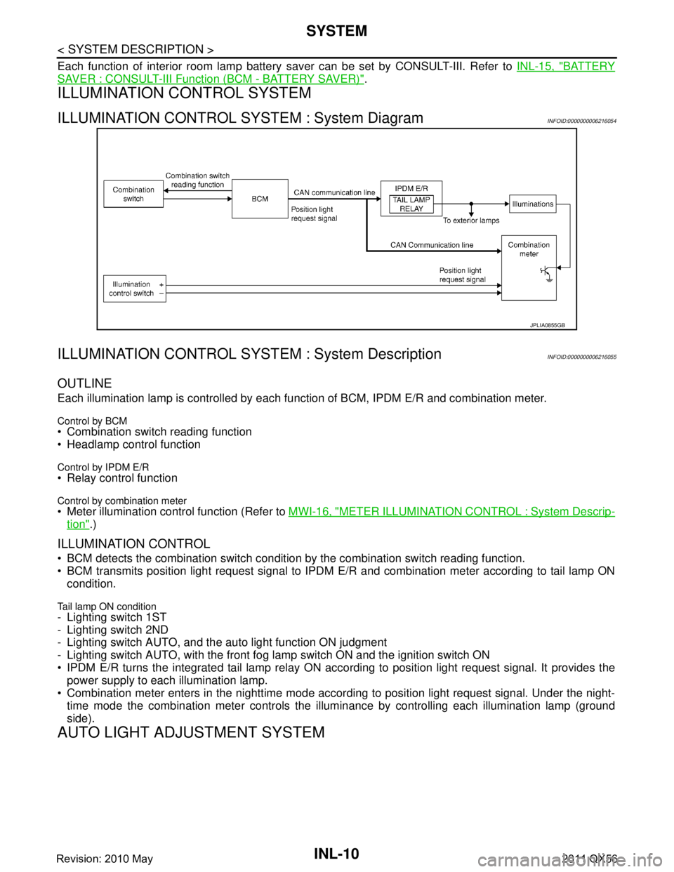
ILLUMINATION CONTROL SYSTEM : System DiagramINFOID:0000000006216054
ILLUMINATION CONTROL SYS TEM : System DescriptionINFOID:0000000006216055
OUTLINE
Each illumination lamp is controlled by each function of BCM, IPDM E/R and combination meter.
Control by BCM Combination switch reading function
Headlamp control function
Control by IPDM E/R Relay control function
Control by combination meter Meter illumination control function (Refer to MWI-16, "METER ILLUMINATION CONTROL : System Descrip-
tion".)
ILLUMINATION CONTROL
BCM detects the combination switch conditi on by the combination switch reading function.
BCM transmits position light request signal to IPDM E/R and combination meter according to tail lamp ON
condition.
Tail lamp ON condition- Lighting switch 1ST
- Lighting switch 2ND
- Lighting switch AUTO, and the auto light function ON judgment
- Lighting switch AUTO, with the front fog lamp switch ON and the ignition switch ON
IPDM E/R turns the integrated tail lamp relay ON acco rding to position light request signal. It provides the
power supply to each illumination lamp.
Combination meter enters in the nighttime mode accord ing to position light request signal. Under the night-
time mode the combination meter controls the illu minance by controlling each illumination lamp (ground
side).
AUTO LIGHT ADJUSTMENT SYSTEM
JPLIA0855GB
Revision: 2010 May2011 QX56
Page 3278 of 5598

SYSTEMINL-11
< SYSTEM DESCRIPTION >
C
DE
F
G H
I
J
K
M A
B
INL
N
O P
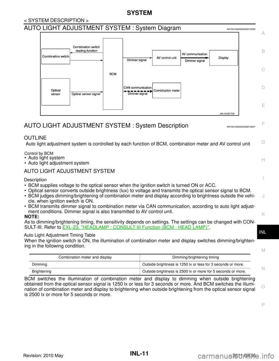
AUTO LIGHT ADJUSTMENT SYSTEM : System DiagramINFOID:0000000006216056
AUTO LIGHT ADJUSTMENT SYSTEM : System DescriptionINFOID:0000000006216057
OUTLINE
Auto light adjustment system is controlled by each f unction of BCM, combination meter and AV control unit
Control by BCM Auto light system
Auto light adjustment system
AUTO LIGHT ADJUSTMENT SYSTEM
Description
BCM supplies voltage to the optical sensor when the ignition switch is turned ON or ACC.
Optical sensor converts outside brightness (lux) to voltage and transmits the optical sensor signal to BCM.
BCM judges dimming/brightening of combination meter and display according to brightness outside the vehi- cle, when ignition switch is ON.
BCM transmits dimmer signal to combination meter via CAN communication, according to auto light adjust- ment conditions. Dimmer signal is also transmitted to AV control unit.
NOTE:
As to dimming/brightening timing, the sensitivity depends on settings. The settings can be changed with CON-
SULT-III. Refer to EXL-23, "
HEADLAMP : CONSULT-III F unction (BCM - HEAD LAMP)".
Auto Light Adjustment Timing Table
When the ignition switch is ON, the illumination of co mbination meter and display switches dimming/brighten-
ing in the following condition.
BCM switches the illumination of combination me ter and display to dimming when outside brightening
obtained from the optical sensor signal is 1250 lx or le ss for 3 seconds or more. And BCM switches the illumi-
nation of combination meter and display to brightening when outside brightening from the optical sensor signal
is 2500 lx or more for 5 seconds or more.
JMLIA0967GB
Combination meter and display Dimming/brightening timing
Dimming Outside brightness is 1250 lx or less for 3 seconds or more.
Brightening Outside brightness is 2500 lx or more for 5 seconds or more.
Revision: 2010 May2011 QX56
Page 3433 of 5598
![INFINITI QX56 2011 Factory Service Manual
LAN
TROUBLE DIAGNOSISLAN-13
< SYSTEM DESCRIPTION > [CAN FUNDAMENTAL]
C
D
E
F
G H
I
J
K L
B A
O P
N
NOTE:
When data link connector branch line is open, transmi
ssion and reception of CAN communicati INFINITI QX56 2011 Factory Service Manual
LAN
TROUBLE DIAGNOSISLAN-13
< SYSTEM DESCRIPTION > [CAN FUNDAMENTAL]
C
D
E
F
G H
I
J
K L
B A
O P
N
NOTE:
When data link connector branch line is open, transmi
ssion and reception of CAN communicati](/manual-img/42/57033/w960_57033-3432.png)
LAN
TROUBLE DIAGNOSISLAN-13
< SYSTEM DESCRIPTION > [CAN FUNDAMENTAL]
C
D
E
F
G H
I
J
K L
B A
O P
N
NOTE:
When data link connector branch line is open, transmi
ssion and reception of CAN communication signals
are not affected. Therefore, no symptoms occur. However, be sure to repair malfunctioning circuit.
The model (all units on CAN communication system are Diag on CAN) cannot perform CAN diagnosis with
CONSULT-III if the following error occurs. The error is judged by the symptom.
Example: Main Line Between Data Link Connector and ABS Actuator and Electr ic Unit (Control Unit) Open Circuit
Unit name Major symptom
ECM
Normal operation.
BCM
EPS control unit
Combination meter
ABS actuator and electric
unit (control unit)
TCM
IPDM E/R
Error Difference of symptom
Data link connector branch line open circuit Normal operation.
CAN-H, CAN-L harness short-circuit Most of the units which are connected to the CAN communication
system enter fail-safe mode or are deactivated.
SKIB8740E
Unit name Major symptom
ECM Engine torque limiting is affected, and shift harshness increases.
BCM Reverse warning chime does not sound.
The front wiper moves under continuous operation mode even though the front wip-
er switch being in the intermittent position.
EPS control unit The steering effort increases.
Combination meter The shift position indicator and OD OFF indicator turn OFF.
The speedometer is inoperative.
The odo/trip meter stops.
ABS actuator and electric unit (control unit) Normal operation.
TCM No impact on operation.
IPDM E/R When the ignition switch is ON,
The headlamps (Lo) turn ON.
The cooling fan continues to rotate.
Revision: 2010 May2011 QX56
Page 3434 of 5598
![INFINITI QX56 2011 Factory Service Manual
LAN-14
< SYSTEM DESCRIPTION >[CAN FUNDAMENTAL]
TROUBLE DIAGNOSIS
Example: CAN-H, CAN-L Harness Short Circuit
CAN Diagnosis with CONSULT-IIIINFOID:0000000006220519
CAN diagnosis on CONSULT-III extract INFINITI QX56 2011 Factory Service Manual
LAN-14
< SYSTEM DESCRIPTION >[CAN FUNDAMENTAL]
TROUBLE DIAGNOSIS
Example: CAN-H, CAN-L Harness Short Circuit
CAN Diagnosis with CONSULT-IIIINFOID:0000000006220519
CAN diagnosis on CONSULT-III extract](/manual-img/42/57033/w960_57033-3433.png)
LAN-14
< SYSTEM DESCRIPTION >[CAN FUNDAMENTAL]
TROUBLE DIAGNOSIS
Example: CAN-H, CAN-L Harness Short Circuit
CAN Diagnosis with CONSULT-IIIINFOID:0000000006220519
CAN diagnosis on CONSULT-III extracts the root
cause by receiving the following information.
Response to the system call
Control unit diagnosis information
Self-diagnosis
CAN diagnostic support monitor
SKIB8741E
Unit name Major symptom
ECM Engine torque limiting is affected, and shift harshness increases.
Engine speed drops.
BCM Reverse warning chime does not sound.
The front wiper moves under continuous operation mode even though the front
wiper switch being in the intermittent position.
The room lamp does not turn ON.
The engine does not start (if an error or malfunction occurs while turning the igni- tion switch OFF.)
The steering lock does not release (if an error or malfunction occurs while turning the ignition switch OFF.)
EPS control unit The steeri ng effort increases.
Combination meter The tachometer and the speedometer do not move.
Warning lamps turn ON.
Indicator lamps do not turn ON.
ABS actuator and electric unit (control unit) Normal operation.
TCM No impact on operation.
IPDM E/R When the ignition switch is ON,
The headlamps (Lo) turn ON.
The cooling fan continues to rotate.
Revision: 2010 May2011 QX56