Page 5570 of 5598

WIPER AND WASHER SYSTEM SYMPTOMSWW-51
< SYMPTOM DIAGNOSIS >
C
DE
F
G H
I
J
K
M A
B
WW
N
O P
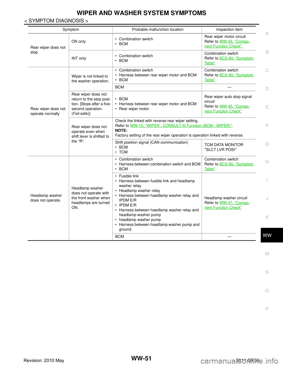
Rear wiper does not
stop ON only
Combination switch
BCM Rear wiper motor circuit
Refer to
WW-43, "
Compo-
nent Function Check".
INT only Combination switch
BCM Combination switch
Refer to
BCS-80, "
Symptom
Ta b l e"
Rear wiper does not
operate normally Wiper is not linked to
the washer operation.
Combination switch
Harness between rear wiper motor and BCM
BCM
Combination switch
Refer to
BCS-80, "
Symptom
Ta b l e"
BCM —
Rear wiper does not
return to the stop posi-
tion. [Stops after a five-
second operation.
(Fail-safe)] BCM
Harness between rear wiper motor and BCM
Rear wiper motor
Rear wiper auto stop signal
circuit
Refer to
WW-45, "
Compo-
nent Function Check"
Rear wiper does not
operate even when
shift lever is shifted to
the “R”. Check the linked with reverse rear wiper setting.
Refer to
WW-15, "WIPER : CONSULT-III Function (BCM - WIPER)".
NOTE:
Factory setting of the rear wiper operation is operation linked with reverse.
Shift position signal (CAN communication)
BCM
TCM TCM DATA MONITOR
″
SLCT LVR POSI ″
Headlamp washer
does not operate. Headlamp washer
does not operate with
the front washer when
headlamps are turned
ON. Combination switch
Harness between combination switch and BCM
BCM
Combination switch
Refer to
BCS-80, "
Symptom
Ta b l e"
Fusible link
Harness between fusible link and headlamp
washer relay
Headlamp washer relay
Harness between haedlamp washer relay and IPDM E/R
IPDM E/R
Harness between haedlamp washer relay and headlamp washer pump
headlamp washer pump
Harness between haedlamp washer pump and ground Headlamp washer circuit
Refer to
WW-47, "
Compo-
nent Function Check"
BCM —
Symptom Probable malfunction location Inspection item
Revision: 2010 May2011 QX56
Page 5574 of 5598
HEADLAMP WASHER NOZZLE AND TUBEWW-55
< REMOVAL AND INSTALLATION >
C
DE
F
G H
I
J
K
M A
B
WW
N
O P
REMOVAL AND INSTALLATION
HEADLAMP WASHER NOZZLE AND TUBE
Exploded ViewINFOID:0000000006220393
Hydraulic LayoutINFOID:0000000006220394
1. Headlamp washer nozzle cover 2. Headlamp washer nozzle assembly 3. Headlamp washer nozzle retainer
4. Headlamp washer nozzle bracket 5. Front bumper fascia : Pawl
JMLIA1096ZZ
1. Headlamp washer nozzle assembly LH 2. Headlamp washer tube 3. Headlamp washer tube (tank side)
4. Headlamp washer nozzle assembly RH 5. Front bumper fascia
A. Metal clip
JMLIA1097ZZ
Revision: 2010 May2011 QX56
Page 5575 of 5598

WW-56
< REMOVAL AND INSTALLATION >
HEADLAMP WASHER NOZZLE AND TUBE
Removal and Installation
INFOID:0000000006220395
REMOVAL
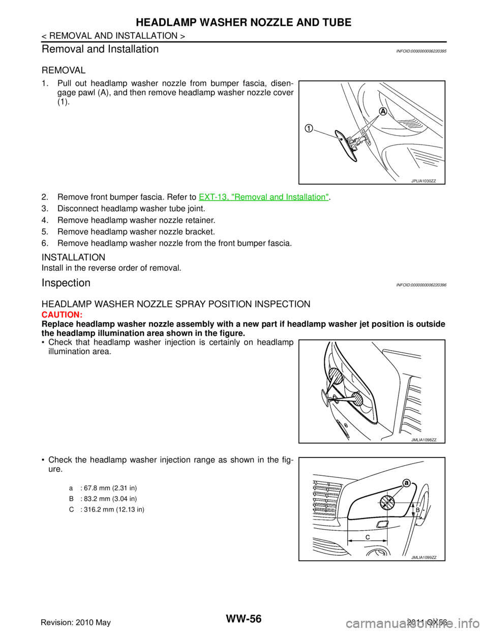
1. Pull out headlamp washer nozzle from bumper fascia, disen- gage pawl (A), and then remove headlamp washer nozzle cover
(1).
2. Remove front bumper fascia. Refer to EXT-13, "
Removal and Installation".
3. Disconnect headlamp washer tube joint.
4. Remove headlamp washer nozzle retainer.
5. Remove headlamp washer nozzle bracket.
6. Remove headlamp washer nozzle from the front bumper fascia.
INSTALLATION
Install in the reverse order of removal.
InspectionINFOID:0000000006220396
HEADLAMP WASHER NOZZLE SPRAY POSITION INSPECTION
CAUTION:
Replace headlamp washer nozzle assembly with a new pa rt if headlamp washer jet position is outside
the headlamp illumination area shown in the figure.
Check that headlamp washer injection is certainly on headlamp
illumination area.
Check the headlamp washer injection range as shown in the fig- ure.
JPLIA1030ZZ
JMLIA1098ZZ
a : 67.8 mm (2.31 in)
B : 83.2 mm (3.04 in)
C : 316.2 mm (12.13 in)
JMLIA1099ZZ
Revision: 2010 May2011 QX56
Page 5576 of 5598
HEADLAMP WASHER NOZZLE AND TUBEWW-57
< REMOVAL AND INSTALLATION >
C
DE
F
G H
I
J
K
M A
B
WW
N
O P
Check the headlamp washer nozzle spray angle.
Outside (A)
Inside (B)
NOTE:
This drawing shows the parts of the headlamp washer nozzle (LH). The headlamp washer nozzle (RH) is
symmetrical of this drawing.
1. Headlamp washer nozzle (outside) 2. Headlamp washer nozzle (inside)
JPLIA1033ZZ
a: 30 °± 3°
b: 70 °± 3°
c: 55 °± 3°
d: 45 °± 3°
Revision: 2010 May2011 QX56
Page 5577 of 5598
WW-58
< REMOVAL AND INSTALLATION >
WASHER TANK
WASHER TANK
Exploded ViewINFOID:0000000006220397
Removal and InstallationINFOID:0000000006220398
REMOVAL
1. Fully open hood.
2. Remove washer tank inlet fixing clip (A).
3. Pull out washer tank inlet (1) from washer tank.
4. Remove fender protector RH (front). Refer to EXT-23, "
FENDER PROTECTOR : Removal and Installa-
tion".
5. Disconnect washer pump connector.
6. Disconnect headlamp washer pump connector.
7. Disconnect washer level switch connector.
8. Disconnect front washer tube and rear washer tube.
9. Disconnect headlamp washer tube joint.
10. Remove washer tank mounting bolts.
1. Washer tank 2. Washer tank inlet
: Vehicle front
Refer to GI-4, "
Components" for the symbols in the figure.
JMLIA0932GB
: Vehicle front
JMLIA0933ZZ
Revision: 2010 May2011 QX56
Page 5580 of 5598
HEADLAMP WASHER PUMPWW-61
< REMOVAL AND INSTALLATION >
C
DE
F
G H
I
J
K
M A
B
WW
N
O P
HEADLAMP WASHER PUMP
Exploded ViewINFOID:0000000006220401
Removal and InstallationINFOID:0000000006220402
REMOVAL
1. Remove washer tank. Refer to WW-58, "Removal and Installation".
2. Remove the mounting bolt, and then remove headlamp washer pump from the washer tank.
3. Remove the packing from the washer tank.
INSTALLATION
Note the following item, and then install in the reverse order of removal.
CAUTION:
Check that there is no leakage after installation or replace packing with new part if it has been dam-
age.
Never twist the packing when inst alling the headlamp washer pump.
1. Washer tank 2. Headlamp washer tube 3. Headlamp washer pump harness
connector
4. Headlamp washer pump 5. Packing : Vehicle front
JMLIA0935ZZ
Revision: 2010 May2011 QX56