Page 2637 of 5598

CAMSHAFTEM-75
< REMOVAL AND INSTALLATION >
C
DE
F
G H
I
J
K L
M A
EM
NP
O
Removal and InstallationINFOID:0000000006289569
REMOVAL
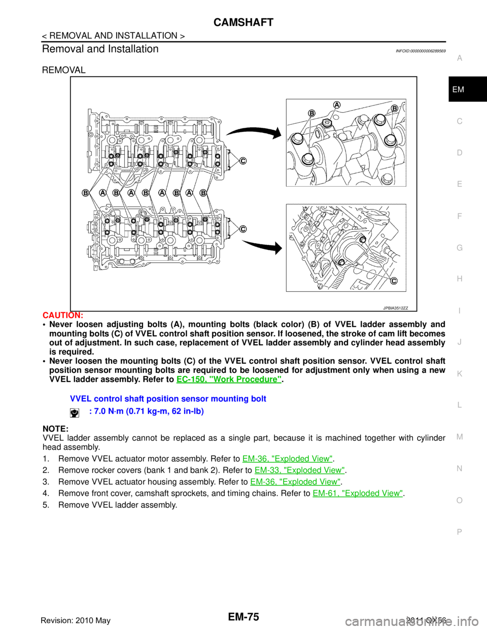
CAUTION:
Never loosen adjusting bolts (A), mounting bolt
s (black color) (B) of VVEL ladder assembly and
mounting bolts (C) of VVEL control shaft position sen sor. If loosened, the stroke of cam lift becomes
out of adjustment. In such case, replacement of VVEL ladder assembly and cylinder head assembly
is required.
Never loosen the mounting bolts (C) of the VVEL control shaft position sensor. VVEL control shaft
position sensor mounting bolts are required to be loosened for adjustment only when using a new
VVEL ladder assembly. Refer to EC-150, "
Work Procedure".
NOTE:
VVEL ladder assembly cannot be replaced as a singl e part, because it is machined together with cylinder
head assembly.
1. Remove VVEL actuator motor assembly. Refer to EM-36, "
Exploded View".
2. Remove rocker covers (bank 1 and bank 2). Refer to EM-33, "
Exploded View".
3. Remove VVEL actuator housing assembly. Refer to EM-36, "
Exploded View".
4. Remove front cover, camshaft sprockets, and timing chains. Refer to EM-61, "
Exploded View".
5. Remove VVEL ladder assembly.
JPBIA3512ZZ
VVEL control shaft positi on sensor mounting bolt
: 7.0 N·m (0.71 kg-m, 62 in-lb)
Revision: 2010 May2011 QX56
Page 2639 of 5598

CAMSHAFTEM-77
< REMOVAL AND INSTALLATION >
C
DE
F
G H
I
J
K L
M A
EM
NP
O
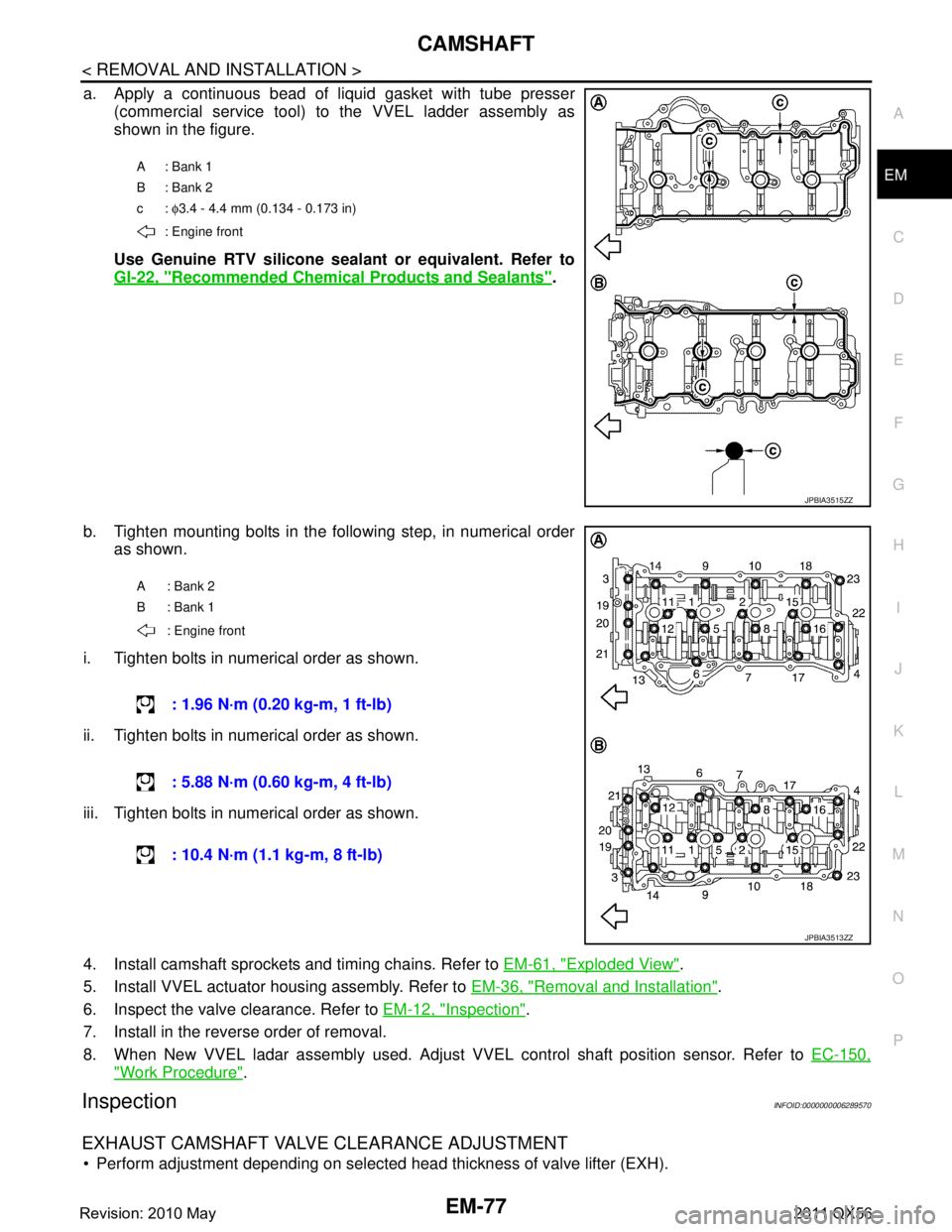
a. Apply a continuous bead of liquid gasket with tube presser
(commercial service tool) to the VVEL ladder assembly as
shown in the figure.
Use Genuine RTV silicone seal ant or equivalent. Refer to
GI-22, "
Recommended Chemical Products and Sealants".
b. Tighten mounting bolts in the following step, in numerical order as shown.
i. Tighten bolts in numerical order as shown.
ii. Tighten bolts in numerical order as shown.
iii. Tighten bolts in numerical order as shown.
4. Install camshaft sprockets and timing chains. Refer to EM-61, "
Exploded View".
5. Install VVEL actuator housing assembly. Refer to EM-36, "
Removal and Installation".
6. Inspect the valve clearance. Refer to EM-12, "
Inspection".
7. Install in the reverse order of removal.
8. When New VVEL ladar assembly used. Adjust VVEL control shaft position sensor. Refer to EC-150,
"Work Procedure".
InspectionINFOID:0000000006289570
EXHAUST CAMSHAFT VALVE CLEARANCE ADJUSTMENT
Perform adjustment depending on selected head thickness of valve lifter (EXH).
A: Bank 1
B: Bank 2
c: φ3.4 - 4.4 mm (0.134 - 0.173 in)
: Engine front
JPBIA3515ZZ
A: Bank 2
B: Bank 1
: Engine front
: 1.96 N·m (0.20 kg-m, 1 ft-lb)
: 5.88 N·m (0.60 kg-m, 4 ft-lb)
: 10.4 N·m (1.1 kg-m, 8 ft-lb)
JPBIA3513ZZ
Revision: 2010 May2011 QX56
Page 2648 of 5598

EM-86
< REMOVAL AND INSTALLATION >
CYLINDER HEAD
CYLINDER HEAD
Exploded ViewINFOID:0000000006289571
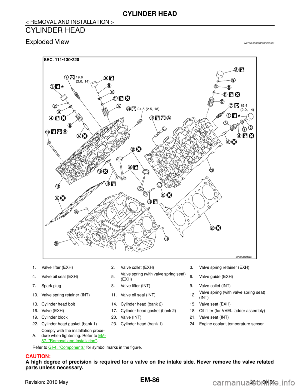
CAUTION:
A high degree of precision is required for a valve on the intake side. Never remove the valve related
parts unless necessary.
1. Valve lifter (EXH) 2. Valve collet (EXH) 3. Valve spring retainer (EXH)
4. Valve oil seal (EXH) 5. Valve spring (with valve spring seat)
(EXH)6. Valve guide (EXH)
7. Spark plug 8. Valve lifter (INT) 9. Valve collet (INT)
10. Valve spring retainer (INT) 11. Valve oil seal (INT) 12. Valve spring (with valve spring seat)
(INT)
13. Cylinder head bolt 14. Cylinder head (bank 2) 15. Valve seat (EXH)
16. Valve (EXH) 17. Cylinder head gasket (bank 2) 18. Oil filter (for VVEL ladder assembly)
19. Cylinder block 20. Valve (INT) 21. Valve seat (INT)
22. Cylinder head gasket (bank 1) 23. Cylinder head (bank 1) 24. Engine coolant temperature sensor
A. Comply with the installation proce-
dure when tightening. Refer to
EM-
87, "Removal and Installation".
Refer to GI-4, "
Components" for symbol marks in the figure.
JPBIA3524GB
Revision: 2010 May2011 QX56
Page 2668 of 5598
EM-106
< UNIT DISASSEMBLY AND ASSEMBLY >
CYLINDER BLOCK
CYLINDER BLOCK
Exploded ViewINFOID:0000000006289582
1. Knock sensor 2. Cylinder block 3. Side bolt
4. Thrust bearing 5. Main bearing (upper) 6. Crankshaft key
7. Crankshaft 8. Main bearing (lower) 9. Main bearing cap
JPBIA4511GB
Revision: 2010 May2011 QX56
Page 2669 of 5598

CYLINDER BLOCKEM-107
< UNIT DISASSEMBLY AND ASSEMBLY >
C
DE
F
G H
I
J
K L
M A
EM
NP
O
Disassembly and AssemblyINFOID:0000000006289583
DISASSEMBLY
1. Remove the following parts:
Oil pans (lower and upper): Refer to EM-54, "
Exploded View" and EM-57, "Exploded View".
Front cover and timing chain: Refer to EM-61, "
Exploded View".
Cylinder head: Refer to EM-86, "
Exploded View".
2. Remove knock sensor. CAUTION:
Carefully handle knock sensor avoiding shocks.
3. Remove oil filter (for VVEL ladder assembly ) from cylinder block, if necessary. Refer to EM-86, "
Exploded
View".
4. Remove piston and connecting rod assembly as per the following: Before removing piston and connecting rod assembly, check the connecting rod side clearance. Refer to
EM-115, "
Inspection".
CAUTION:
Be careful not to drop connecting r od bearing, and to scratch the surface.
a. Position crankshaft pin corresponding to connecting rod to be removed onto the bottom dead center.
b. Loosen mounting bolts, and remove connecting rod bearing cap.
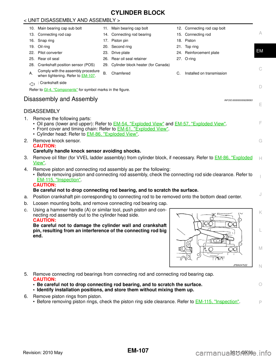
c. Using a hammer handle (A) or similar tool, push piston and con- necting rod assembly out to the cylinder head side.
CAUTION:
Be careful not to damage the cylinder wall and crankshaft
pin, resulting from an interf erence of the connecting rod big
end.
5. Remove connecting rod bearings from connecting rod and connecting rod bearing cap.
CAUTION:
Be careful not to drop connecting rod bearing, and to scratch the surface.
Identify installation positions, and store them without mixing them up.
6. Remove piston rings from piston. Before removing piston rings, check the piston ring side clearance. Refer to EM-115, "
Inspection".
10. Main bearing cap sub bolt 11. Main bearing cap bolt 12. Connecting rod cap bolt
13. Connecting rod cap 14. Connecting rod bearing 15. Connecting rod
16. Snap ring 17. Piston pin 18. Piston
19. Oil ring 20. Second ring 21. Top ring
22. Pilot converter 23. Drive plate 24. Reinforcement plate
25. Rear oil seal 26. Rear oil seal retainer 27. O-ring
28. Crankshaft position sensor (POS) 29. Cylinder block heater (for Canada)
A.Comply with the assembly procedure
when tightening. Refer to
EM-107
.B. Chamfered C. Installed on transmission
: Crankshaft side
Refer to GI-4, "
Components" for symbol marks in the figure.
JPBIA2475ZZ
Revision: 2010 May2011 QX56
Page 2677 of 5598
![INFINITI QX56 2011 Factory Service Manual
CYLINDER BLOCKEM-115
< UNIT DISASSEMBLY AND ASSEMBLY >
C
DE
F
G H
I
J
K L
M A
EM
NP
O
f. Tighten connecting rod bolts. (clockwise)
CAUTION:
Always use the angle wrench [SST: KV10112100 (B T8653-A)]. INFINITI QX56 2011 Factory Service Manual
CYLINDER BLOCKEM-115
< UNIT DISASSEMBLY AND ASSEMBLY >
C
DE
F
G H
I
J
K L
M A
EM
NP
O
f. Tighten connecting rod bolts. (clockwise)
CAUTION:
Always use the angle wrench [SST: KV10112100 (B T8653-A)].](/manual-img/42/57033/w960_57033-2676.png)
CYLINDER BLOCKEM-115
< UNIT DISASSEMBLY AND ASSEMBLY >
C
DE
F
G H
I
J
K L
M A
EM
NP
O
f. Tighten connecting rod bolts. (clockwise)
CAUTION:
Always use the angle wrench [SST: KV10112100 (B T8653-A)]. Never make judgment by visual
inspection.
After tightening connecting rod bolts, c heck that crankshaft rotates smoothly.
Check the connecting rod side clearance. Refer to EM-115, "
Inspection".
16. Install knock sensors (1). Install knock sensors in the direction shown in the figure.
After installing knock sens or, connect harness connector, and
lay it out to front of the engine.
CAUTION:
Never tighten mounting bolts while holding connector.
If any impact by dropping is applied to knock sensor,
replace it with new one.
NOTE:
Check that there is no foreign material on the cylinder block
mating surface and the back surface of knock sensor.
Check that knock sensor does not interfere with other parts.
17. Install oil filter (for VVEL ladder assembly).
18. Install drive plate. Install drive plate (4) and reinforcement plate (3) as shown inthe figure.
When installing drive plate to crankshaft (1), be sure to cor- rectly align crankshaft side dowel pin and drive plate side
dowel pin hole.
CAUTION:
If these are not aligned correct ly, engine runs roughly and
“MIL” illuminates.
Holding ring gear with the ring gear stopper [SST: KV10119200 (J-49277)].
Tighten the mounting bolts crosswise over several times.
19. Assemble in the reverse order of disassembly.
InspectionINFOID:0000000006289584
CRANKSHAFT END PLAY
Measure the clearance between thrust bearings and crankshaft arm when crankshaft is moved fully forward or backward with a dial
indicator (A).
If the measured value exceeds t he limit, replace thrust bearings,
and measure again. If it still exceeds the limit, replace crankshaft
also. : 19.6 N·m (2.0 kg-m, 14.5 ft-lb)
Angle tightening: 90 degrees
: Engine front
2 : Pilot converter
A : Rounded : Engine front
JPBIA4515ZZ
JPBIA2275ZZ
Standard and limit : Refer to EM-137, "CylinderBlock".
JPBIA2477ZZ
Revision: 2010 May2011 QX56
Page 2707 of 5598
PREPARATIONEX-3
< PREPARATION >
C
DE
F
G H
I
J
K L
M A
EX
NP
O
PREPARATION
PREPARATION
Special Service ToolINFOID:0000000006289692
Commercial Service ToolINFOID:0000000006289693
Tool number
(Kent-Moore No.)
Tool name
Description
KV10114400
(J-38365)
Heated oxygen sensor wrench Loosening or tightening heated oxygen sen-
sor 2
For 22 mm (0.87 in) (a) width hexagon nut
S-NT636
Tool name
Description
Power tool Loosening bolts and nuts
PBIC0190E
Revision: 2010 May2011 QX56
Page 2709 of 5598
EXHAUST SYSTEMEX-5
< REMOVAL AND INSTALLATION >
C
DE
F
G H
I
J
K L
M A
EX
NP
O
REMOVAL AND INSTALLATION
EXHAUST SYSTEM
Exploded ViewINFOID:0000000006289695
Removal and InstallationINFOID:0000000006289696
REMOVAL
Disconnect each joint and mounting using power tool.
Remove heated oxygen sens
or 2, as follows:.
1. Mounting rubber 2. Mounting bracket 3. Rear mufller
4. Dynamic damper 5. Mounting rubber 6. Mounting bracket
7. Mounting rubber 8. Gasket 9. Main muffler
10. Mounting rubber 11. Mounting bracket 12. Mounting rubber
13. Gasket 14. Exhaust front tube (RH) 15. Exhaust front tube (LH)
16. Heated oxygen sensor 2 (bank 2) 17. Heated oxygen sensor 2 (bank 1) 18. Ring gasket
Refer to GI-4, "
Components" for symbols in the figure.
JPBIA3265GB
Revision: 2010 May2011 QX56