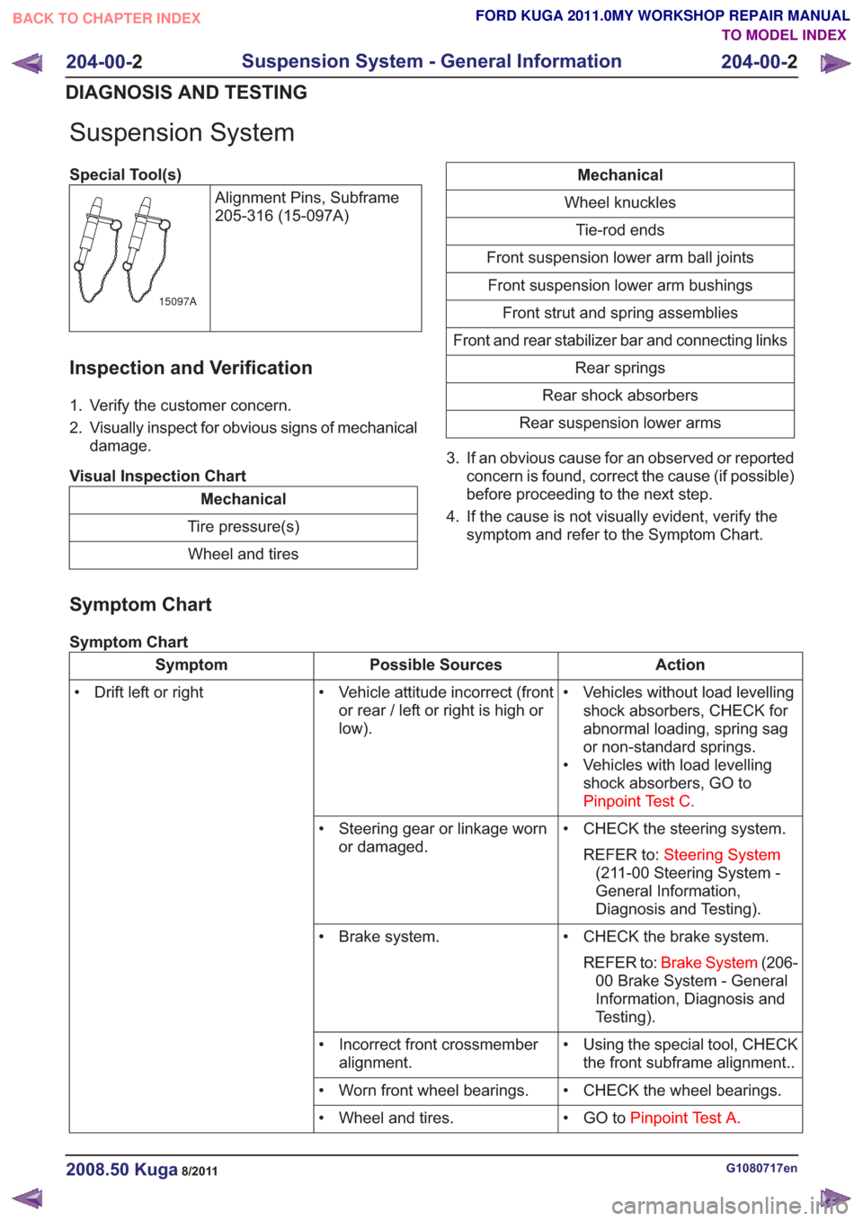
Page 100 of 2057

Suspension System
Special Tool(s)Alignment Pins, Subframe
205-316 (15-097A)
15097A
Inspection and Verification
1. Verify the customer concern.
2. Visually inspect for obvious signs of mechanicaldamage.
Visual Inspection Chart
Mechanical
Tire pressure(s) Wheel and tires
Mechanical
Wheel knuckles Tie-rod ends
Front suspension lower arm ball joints Front suspension lower arm bushings Front strut and spring assemblies
Front and rear stabilizer bar and connecting links Rear springs
Rear shock absorbers
Rear suspension lower arms
3. If an obvious cause for an observed or reported concern is found, correct the cause (if possible)
before proceeding to the next step.
4. If the cause is not visually evident, verify the symptom and refer to the Symptom Chart.
Symptom Chart
Symptom Chart
Action
Possible Sources
Symptom
• Vehicles without load levellingshock absorbers, CHECK for
abnormal loading, spring sag
or non-standard springs.
• Vehicles with load levelling shock absorbers, GO to
Pinpoint Test C.
• Vehicle attitude incorrect (front
or rear / left or right is high or
low).
• Drift left or right
• CHECK the steering system.REFER to: Steering System
(211-00 Steering System -
General Information,
Diagnosis and Testing).
• Steering gear or linkage worn
or damaged.
• CHECK the brake system.REFER to: Brake System (206-
00 Brake System - General
Information, Diagnosis and
Testing).
• Brake system.
• Using the special tool, CHECKthe front subframe alignment..
• Incorrect front crossmember
alignment.
• CHECK the wheel bearings.
• Worn front wheel bearings.
• GO toPinpoint Test A.
• Wheel and tires.
G1080717en2008.50 Kuga8/2011
204-00- 2
Suspension System - General Information
204-00- 2
DIAGNOSIS AND TESTING
TO MODEL INDEX
BACK TO CHAPTER INDEX
FORD KUGA 2011.0MY WORKSHOP REPAIR MANUAL
Page 101 of 2057
Condenser
General EquipmentCable TiesMaterials
Specification
Name
WSH-M1C231-B /
6U7J-M1C231-AA
Compressor Oil - Air
Conditioning
Removal
NOTE:
Removal steps in this procedure may
contain installation details. 1.
Refer to: Air Conditioning (A/C) System
Recovery, Evacuation and Charging (412-00
Climate Control System - General Information,
General Procedures).
2. CAUTION: Make sure that all openings are sealed. Use new blanking caps.
1. Torque: 5Nm
2. Torque: 8Nm
E100847
1
2
2
G1022366en2008.50 Kuga8/2011
412-01- 31
Climate Control
412-01- 31
REMOVAL AND INSTALLATION
TO MODEL INDEX
BACK TO CHAPTER INDEX
FORD KUGA 2011.0MY WORKSHOP REPAIR MANUAL
Page 102 of 2057
3.Refer to: Lifting(100-02 Jacking and Lifting,
Description and Operation).
4.
E98183
5.
E98184
Vehicles with automatic transmission
6. General Equipment: Cable Ties
E112626
1
2
1
2
All vehicles
7.Torque: 5Nm
G1022366en2008.50 Kuga8/2011
412-01- 32
Climate Control
412-01- 32
REMOVAL AND INSTALLATION
TO MODEL INDEX
BACK TO CHAPTER INDEX
FORD KUGA 2011.0MY WORKSHOP REPAIR MANUAL
Page 103 of 2057
8.
G1022366en2008.50 Kuga8/2011
412-01-33
Climate Control
412-01- 33
REMOVAL AND INSTALLATION
TO MODEL INDEX
BACK TO CHAPTER INDEX
FORD KUGA 2011.0MY WORKSHOP REPAIR MANUAL
1
2
1
11
E77215
E99948
Page 104 of 2057
Installation
1.To install, reverse the removal procedure.
2. Coat the O-ring seals on the refrigerant lines.
Material: Compressor Oil - Air Conditioning
(WSH-M1C231-B / 6U7J-M1C231-AA)
refrigerant oil
G1022366en2008.50 Kuga8/2011
412-01- 34
Climate Control
412-01- 34
REMOVAL AND INSTALLATION
TO MODEL INDEX
BACK TO CHAPTER INDEX
FORD KUGA 2011.0MY WORKSHOP REPAIR MANUAL
Page 105 of 2057
Clutch and Clutch Field Coil
General EquipmentPuller
Removal
1. Refer to: Air Conditioning (A/C) Compressor -
2.5L Duratec (147kW/200PS) - VI5 (412-01
Climate Control, Removal and Installation).
2. Torque: 13
Nm
E112210
3.General Equipment: Puller
E112211
4. NOTE: Note the position of the component
before removal.
E112212
Installation
1. NOTE: Make sure that the component is
installed to the position noted before removal.
To install, reverse the removal procedure.
2. Refer to: Air Conditioning (A/C) Clutch Air Gap
Adjustment (412-00 Climate Control System
- General Information, General Procedures).
G1158272en2008.50 Kuga8/2011
412-01- 35
Climate Control
412-01- 35
REMOVAL AND INSTALLATION
TO MODEL INDEX
BACK TO CHAPTER INDEX
FORD KUGA 2011.0MY WORKSHOP REPAIR MANUAL
Page 106 of 2057
Pollen Filter — RHD
Removal
1.
E51159
2.
E101552
3.
E101637
4.
E101638
x3
Installation
1.To install, reverse the removal procedure.
G1066764en2008.50 Kuga8/2011
412-01- 36
Climate Control
412-01- 36
REMOVAL AND INSTALLATION
TO MODEL INDEX
BACK TO CHAPTER INDEX
FORD KUGA 2011.0MY WORKSHOP REPAIR MANUAL
Page 107 of 2057
Blower Motor — RHD(34 374 0)
Special Tool(s)412-131
Remover/Installer, Blower
Engine
E42948
Removal
NOTE:Removal steps in this procedure may
contain installation details.
1. Refer to: Cowl Panel Grille (501-02 Front End
Body Panels, Removal and Installation).
2. Torque: 25
Nm
E101389
3.Refer to: Steering Column (211-04 Steering
Column, Removal and Installation).
4. Refer to: Floor Console Extension - Vehicles
With: Center Armrest (501-12 Instrument
Panel and Console, Removal and Installation).
5.
E102293
6. Torque: 25Nm
G1065500en2008.50 Kuga8/2011
412-01- 37
Climate Control
412-01- 37
REMOVAL AND INSTALLATION
TO MODEL INDEX
BACK TO CHAPTER INDEX
FORD KUGA 2011.0MY WORKSHOP REPAIR MANUAL