2011 FORD KUGA ASSEMBLY
[x] Cancel search: ASSEMBLYPage 8 of 2057

About This Manual
Introduction
This manual covers diagnosis and testing and
repair procedures.
It is structured into groups and sections, with
specific system sections grouped together under
their relevant group.
A group covers a specific portion of the vehicle.
The manual is divided into five groups, General
Information, Chassis, Powertrain, Electrical and
Body and Paint. The number of the group is the
first number of a section number.
Within Etis, the navigation tree will list the groups.
After selecting a group the navigation tree will then
list the sections within that group. Each section has
a contents list detailing Specifications, Description
and Operation, Diagnosis and Testing, General
Procedures, Disassembly and Assembly, Removal
and Installation.
References to LH (left-hand) and RH
(right-hand)
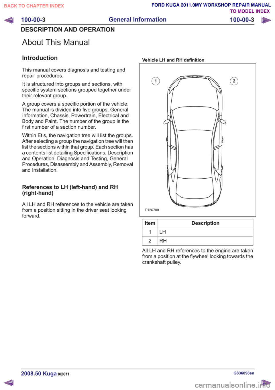
All LH and RH references to the vehicle are taken
from a position sitting in the driver seat looking
forward.
Vehicle LH and RH definition
E126780
12
Description
Item
LH
1
RH
2
All LH and RH references to the engine are taken
from a position at the flywheel looking towards the
crankshaft pulley.
G836098en2008.50 Kuga8/2011
100-00- 3
General Information
100-00- 3
DESCRIPTION AND OPERATION
TO MODEL INDEX
BACK TO CHAPTER INDEX
FORD KUGA 2011.0MY WORKSHOP REPAIR MANUAL
Page 62 of 2057

TIM0103001
WARNING: Make sure that the ends of the
jumper cables do not touch each other or
ground against the vehicle body at any
time while the cables are attached to the
battery. A fully charged battery, if shorted
through jumper cables, can discharge at
a rate well above 1000 amps causing
violent arcing and very rapid heating of the
jumper cables and terminals, and can even
cause the battery to explode. Failure to
follow these instructions may result in
personal injury.
Always connect the jumper cables in the following
sequence:
– Slave battery positive first and then vehicle battery positive.
– Slave battery negative next and then vehicle ground at least 12 inches (300 mm) from the
battery terminal, for example engine lifting eye.
Always reduce the engine speed to idle before
disconnecting the jumper cables.
Before removing the jumper cables from the vehicle
that had the discharged battery, switch on the
heater blower (high) or the heated rear window, to
reduce the voltage peak when the cables are
removed.
Always disconnect the jumper cables in the reverse
order to the connecting sequence and do not short
the ends of the cables.
Do not rely on the generator to restore a
discharged battery. For a generator to recharge a
battery, it would take in excess of eight hours
continuous driving with no additional loads placed
on the battery.
Component Cleaning
To prevent the ingress of dirt, accumulations of
loose dirt and greasy deposits should be removed before disconnecting or dismantling components
or assemblies.
Components should be thoroughly cleaned before
inspection prior to reassembly.
Cleaning Methods:
– Dry cleaning.
– Removal of loose dirt with soft or cable brushes.
– Scraping dirt off with a piece of metal or wood.
– Wiping off with a rag.
WARNING: Wear eye protection when
cleaning vehicle components with
compressed air, a steam cleaner or a
power washer. Failure to follow this
instruction may result in personal injury.
CAUTIONS:
Compressed air is sometimes 'wet' so use
with caution, especially on hydraulic
systems.
To prevent damage to the electrical
connectors in the engine compartment, do
not use a steam cleaner or a power washer
to clean the engine compartment.
– Blowing dirt off with compressed air.
– Removal of dry dust using vacuum equipment. This method must always be used to remove
friction lining material dust (asbestos particles).
– Steam cleaning.
WARNING: Most solvents require careful
handling and some are harmful. Refer to
Health and Safety Precautions and to the
manufacturers literature for the relevant
safety precautions. Failure to follow these
instructions may result in personal injury.
Various solvents are available which are suitable
for component cleaning. Some components, such
as brake hydraulic parts and electrical assemblies
should be cleaned only with recommended solvents
— refer to Solvents, Sealers and Adhesives or to
the section of the manual relevant to the
component.
Calibration of Essential Measuring
Equipment
WARNING: Equipment, which requires
regular calibration, must be calibrated in
accordance with the manufacturers
G17373en2008.50 Kuga8/2011
100-00- 55
General Information
100-00- 55
DESCRIPTION AND OPERATION
TO MODEL INDEX
BACK TO CHAPTER INDEX
FORD KUGA 2011.0MY WORKSHOP REPAIR MANUAL
Page 109 of 2057

10.
1
3
2
E101554
11. CAUTION: Make sure that the blowermotor and fan assembly is placed on
the bench with the fan pointing
upwards.
Special Tool(s): 412-131
E101555
412-131
Installation
1. NOTE: The component can only be installed in
1 position.
To install, reverse the removal procedure.
G1065500en2008.50 Kuga8/2011
412-01- 39
Climate Control
412-01- 39
REMOVAL AND INSTALLATION
TO MODEL INDEX
BACK TO CHAPTER INDEX
FORD KUGA 2011.0MY WORKSHOP REPAIR MANUAL
Page 154 of 2057

SECTION 412-02 Auxiliary Climate Control
VEHICLE APPLICATION:
2008.50 Kuga
PAGE
CONTENTS
DESCRIPTION AND OPERATION
412-02-2
Auxiliary Climate Control (Component Location) ................................................................
412-02-4
Auxiliary Climate Control (Overview) ..................................................................................
412-02-4
Initial start-up of the fuel-fired booster heater .....................................................................
412-02-4
Lockout ...............................................................................................................................
412-02-4
Unlocking the control unit ...................................................................................................
412-02-5
Auxiliary Climate Control (System Operation and Component Description) ......................
412-02-5
System Diagram.................................................................................................................
412-02-12
System Operation ...............................................................................................................
412-02-12
Electric Booster Heater ...................................................................................................
412-02-12
Fuel-fired heater - function diagram................................................................................
412-02-13
Boost heat mode.............................................................................................................
412-02-13
Programmable fuel fired booster heater .........................................................................
412-02-13
Immediate start-up of the booster heater ........................................................................
412-02-13
Programmed start-up of the booster heater ....................................................................
412-02-14
Emergency shutoff ..........................................................................................................
412-02-14
Component Description ......................................................................................................412-02-14Electric Booster Heater...................................................................................................
412-02-14Detailed illustration of fuel-fired heater ...........................................................................
412-02-16Flame sensor..................................................................................................................
412-02-16Overheat Sensor.............................................................................................................
412-02-16ECT.................................................................................................................................
412-02-16Water pump....................................................................................................................
412-02-16Fuel pump.......................................................................................................................
REMOVAL AND INSTALLATION 412-02-17
Auxiliary Coolant Flow Pump ..............................................................................................
412-02-18
Electric Booster Heater .......................................................................................................
412-02-21
Fuel Fired Booster Heater — 2.5L Duratec (147kW/200PS) - VI5 .....................................
412-02-25
Fuel Fired Booster Heater Fuel Pump ................................................................................
DISASSEMBLY AND ASSEMBLY 412-02-26
Fuel Fired Booster Heater .................................................................................................. 412-02-1
Auxiliary Climate Control
412-02-1
.
TO MODEL INDEX
BACK TO CHAPTER INDEX
FORD KUGA 2011.0MY WORKSHOP REPAIR MANUAL
Page 160 of 2057

Description
Item
Electric Booster HeaterRefer to Component Description: (page
?)
1
GEM (generic electronic module)
2
Outside temperature sensor
3
Climate control system control assembly
4 Description
Item
Generator and Alternator
5
PCM (powertrain control module)
6
Coolant temperature sensor (ECT (engine
coolant temperature) sensor)Refer to Component Description: ECT
(page ?)
7
instrument cluster
8 G1066982en
2008.50 Kuga 8/2011 412-02-7
Auxiliary Climate Control
412-02-7
DESCRIPTION AND OPERATIONTO MODEL INDEX
BACK TO CHAPTER INDEX
FORD KUGA 2011.0MY WORKSHOP REPAIR MANUAL
Page 162 of 2057

Description
Item
Electric Booster HeaterRefer to Component Description: (page
?)
1
GEM2
Outside temperature sensor
3
Climate control system control assembly
4 Description
Item
Generator and Alternator
5
PCM6
Coolant temperature sensor (ECT sensor)Refer to Component Description: ECT
(page ?)
7
instrument cluster
8 G1066982en
2008.50 Kuga 8/2011 412-02-9
Auxiliary Climate Control
412-02-9
DESCRIPTION AND OPERATIONTO MODEL INDEX
BACK TO CHAPTER INDEX
FORD KUGA 2011.0MY WORKSHOP REPAIR MANUAL
Page 171 of 2057

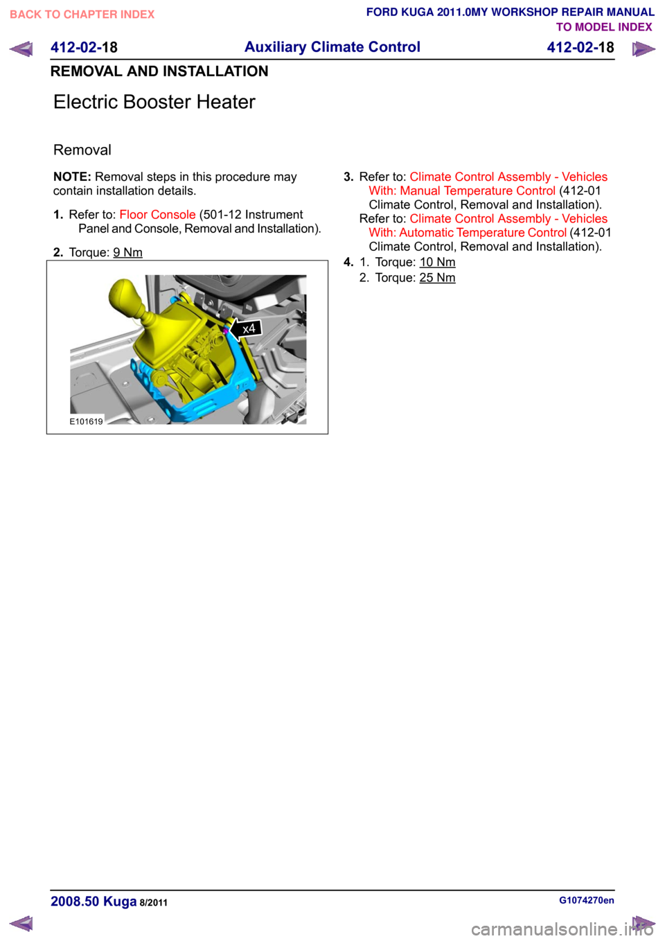
Electric Booster Heater
Removal
NOTE:
Removal steps in this procedure may
contain installation details.
1. Refer to: Floor Console (501-12 Instrument
Panel and Console, Removal and Installation).
2. Torque: 9 Nm 3.
Refer to: Climate Control Assembly - Vehicles
With: Manual Temperature Control (412-01
Climate Control, Removal and Installation).
Refer to: Climate Control Assembly - Vehicles
With: Automatic Temperature Control (412-01
Climate Control, Removal and Installation).
4. Torque: 10 Nm1.
2. Torque: 25
Nm
G1074270en
2008.50 Kuga 8/2011 412-02-18
Auxiliary Climate Control
412-02-18
REMOVAL AND INSTALLATIONTO MODEL INDEX
BACK TO CHAPTER INDEX
FORD KUGA 2011.0MY WORKSHOP REPAIR MANUALx4E101619
Page 179 of 2057

Fuel Fired Booster Heater
General Equipment
Flat-bladed screwdriver
Disassembly
NOTE: Removal steps in this procedure may
contain installation details.
1. Refer to: Engine Cooling System Health and
Safety Precautions (100-00 General
Information, Description and Operation).
2. 3. 4.
5.
6.
G1163567en
2008.50 Kuga 8/2011 412-02-26
Auxiliary Climate Control
412-02-26
DISASSEMBLY AND ASSEMBLYTO MODEL INDEX
BACK TO CHAPTER INDEX
FORD KUGA 2011.0MY WORKSHOP REPAIR MANUALx4E112695 E112696x4 E112697 E112698x4 E112699