2011 FORD KUGA ASSEMBLY
[x] Cancel search: ASSEMBLYPage 1201 of 2057
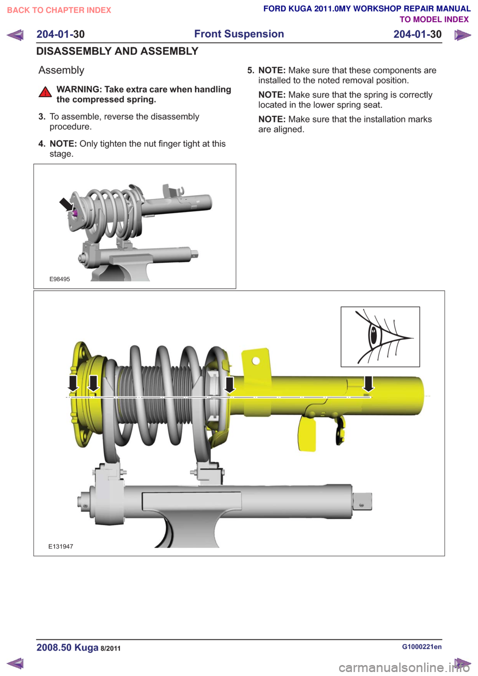
Assembly
WARNING: Take extra care when handling
the compressed spring.
3. To assemble, reverse the disassembly
procedure.
4. NOTE: Only tighten the nut finger tight at this
stage.
E98495
5. NOTE: Make sure that these components are
installed to the noted removal position.
NOTE: Make sure that the spring is correctly
located in the lower spring seat.
NOTE: Make sure that the installation marks
are aligned.
E131947
G1000221en2008.50 Kuga8/2011
204-01- 30
Front Suspension
204-01- 30
DISASSEMBLY AND ASSEMBLY
TO MODEL INDEX
BACK TO CHAPTER INDEX
FORD KUGA 2011.0MY WORKSHOP REPAIR MANUAL
Page 1202 of 2057
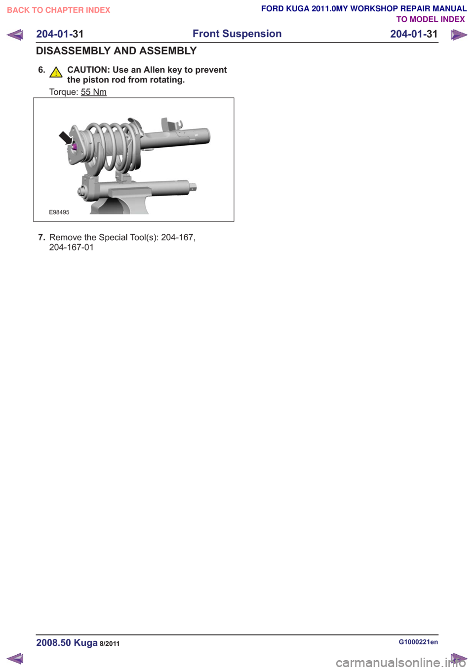
6. CAUTION: Use an Allen key to preventthe piston rod from rotating.
Torque: 55Nm
E98495
7.Remove the Special Tool(s): 204-167,
204-167-01
G1000221en2008.50 Kuga8/2011
204-01- 31
Front Suspension
204-01- 31
DISASSEMBLY AND ASSEMBLY
TO MODEL INDEX
BACK TO CHAPTER INDEX
FORD KUGA 2011.0MY WORKSHOP REPAIR MANUAL
Page 1235 of 2057
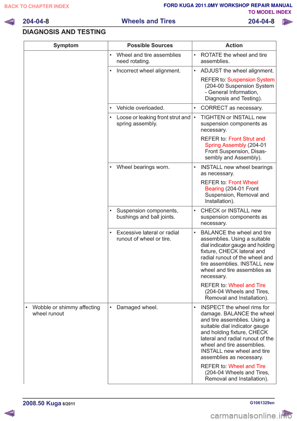
Action
Possible Sources
Symptom
• ROTATE the wheel and tireassemblies.
• Wheel and tire assemblies
need rotating.
• ADJUST the wheel alignment.REFER to: Suspension System
(204-00 Suspension System
- General Information,
Diagnosis and Testing).
• Incorrect wheel alignment.
• CORRECT as necessary.
• Vehicle overloaded.
• TIGHTEN or INSTALL newsuspension components as
necessary.
REFER to: Front Strut and
Spring Assembly (204-01
Front Suspension, Disas-
sembly and Assembly).
• Loose or leaking front strut and
spring assembly.
• INSTALL new wheel bearingsas necessary.
REFER to: Front Wheel
Bearing (204-01 Front
Suspension, Removal and
Installation).
• Wheel bearings worn.
• CHECK or INSTALL newsuspension components as
necessary.
• Suspension components,
bushings and ball joints.
• BALANCE the wheel and tireassemblies. Using a suitable
dial indicator gauge and holding
fixture, CHECK lateral and
radial runout of the wheel and
tire assemblies. INSTALL new
wheel and tire assemblies as
necessary.
REFER to: Wheel and Tire
(204-04 Wheels and Tires,
Removal and Installation).
• Excessive lateral or radial
runout of wheel or tire.
• INSPECT the wheel rims fordamage. BALANCE the wheel
and tire assemblies. Using a
suitable dial indicator gauge
and holding fixture, CHECK
lateral and radial runout of the
wheel and tire assemblies.
INSTALL new wheel and tire
assemblies as necessary.
REFER to: Wheel and Tire
(204-04 Wheels and Tires,
Removal and Installation).
• Damaged wheel.
• Wobble or shimmy affecting
wheel runout
G1061329en2008.50 Kuga8/2011
204-04- 8
Wheels and Tires
204-04- 8
DIAGNOSIS AND TESTING
TO MODEL INDEX
BACK TO CHAPTER INDEX
FORD KUGA 2011.0MY WORKSHOP REPAIR MANUAL
Page 1236 of 2057
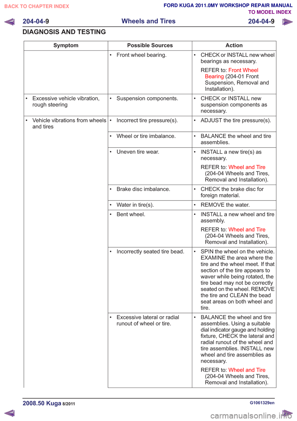
Action
Possible Sources
Symptom
• CHECK or INSTALL new wheelbearings as necessary.
REFER to: Front Wheel
Bearing (204-01 Front
Suspension, Removal and
Installation).
• Front wheel bearing.
• CHECK or INSTALL newsuspension components as
necessary.
• Suspension components.
• Excessive vehicle vibration,
rough steering
• ADJUST the tire pressure(s).
• Incorrect tire pressure(s).
• Vehicle vibrations from wheels
and tires
• BALANCE the wheel and tireassemblies.
• Wheel or tire imbalance.
• INSTALL a new tire(s) asnecessary.
REFER to: Wheel and Tire
(204-04 Wheels and Tires,
Removal and Installation).
• Uneven tire wear.
• CHECK the brake disc forforeign material.
• Brake disc imbalance.
• REMOVE the water.
• Water in tire(s).
• INSTALL a new wheel and tireassembly.
REFER to: Wheel and Tire
(204-04 Wheels and Tires,
Removal and Installation).
• Bent wheel.
• SPIN the wheel on the vehicle.EXAMINE the area where the
tire and the wheel meet. If that
section of the tire appears to
waver while being rotated, the
tire bead may not be correctly
seated on the wheel. REMOVE
the tire and CLEAN the bead
seat areas on both wheel and
tire.
• Incorrectly seated tire bead.
• BALANCE the wheel and tireassemblies. Using a suitable
dial indicator gauge and holding
fixture, CHECK the lateral and
radial runout of the wheel and
tire assemblies. INSTALL new
wheel and tire assemblies as
necessary.
REFER to: Wheel and Tire
(204-04 Wheels and Tires,
Removal and Installation).
• Excessive lateral or radial
runout of wheel or tire.
G1061329en2008.50 Kuga8/2011
204-04- 9
Wheels and Tires
204-04- 9
DIAGNOSIS AND TESTING
TO MODEL INDEX
BACK TO CHAPTER INDEX
FORD KUGA 2011.0MY WORKSHOP REPAIR MANUAL
Page 1246 of 2057
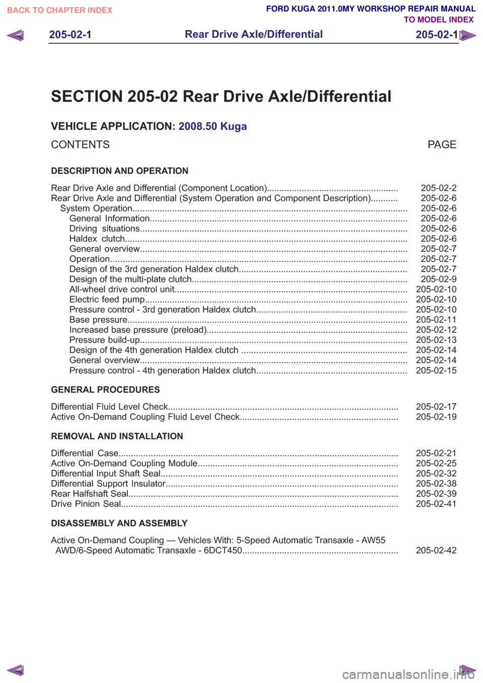
SECTION 205-02 Rear Drive Axle/Differential
VEHICLE APPLICATION:2008.50 Kuga
PA G E
CONTENTS
DESCRIPTION AND OPERATION
205-02-2
Rear Drive Axle and Differential (Component Location) .....................................................
205-02-6
Rear Drive Axle and Differential (System Operation and Component Description) ...........
205-02-6
System Operation ........................................................................\
.......................................
205-02-6
General Information ........................................................................\
................................
205-02-6
Driving situations ........................................................................\
....................................
205-02-6
Haldex clutch ........................................................................\
..........................................
205-02-7
General overview ........................................................................\
....................................
205-02-7
Operation ........................................................................\
................................................
205-02-7
Design of the 3rd generation Haldex clutch ....................................................................
205-02-9
Design of the multi-plate clutch ........................................................................\
...............
205-02-10
All-wheel drive control unit ........................................................................\
......................
205-02-10
Electric feed pump ........................................................................\
..................................
205-02-10
Pressure control - 3rd generation Haldex clutch .............................................................
205-02-11
Base pressure ........................................................................\
.........................................
205-02-12
Increased base pressure (preload) ........................................................................\
.........
205-02-13
Pressure build-up ........................................................................\
....................................
205-02-14
Design of the 4th generation Haldex clutch ...................................................................
205-02-14
General overview ........................................................................\
....................................
205-02-15
Pressure control - 4th generation Haldex clutch .............................................................
GENERAL PROCEDURES 205-02-17
Differential Fluid Level Check ........................................................................\
.....................
205-02-19
Active On-Demand Coupling Fluid Level Check ................................................................
REMOVAL AND INSTALLATION 205-02-21
Differential Case ........................................................................\
.........................................
205-02-25
Active On-Demand Coupling Module ........................................................................\
.........
205-02-32
Differential Input Shaft Seal ........................................................................\
........................
205-02-38
Differential Support Insulator ........................................................................\
......................
205-02-39
Rear Halfshaft Seal ........................................................................\
.....................................
205-02-41
Drive Pinion Seal ........................................................................\
........................................
DISASSEMBLY AND ASSEMBLY
205-02-42
Active On-Demand Coupling — Vehicles With: 5-Speed Automatic Transaxle - AW55
AWD/6-Speed Automatic Transaxle - 6DCT450 ...............................................................
205-02-1
Rear Drive Axle/Differential
205-02- 1
.
TO MODEL INDEX
BACK TO CHAPTER INDEX
FORD KUGA 2011.0MY WORKSHOP REPAIR MANUAL
Page 1247 of 2057
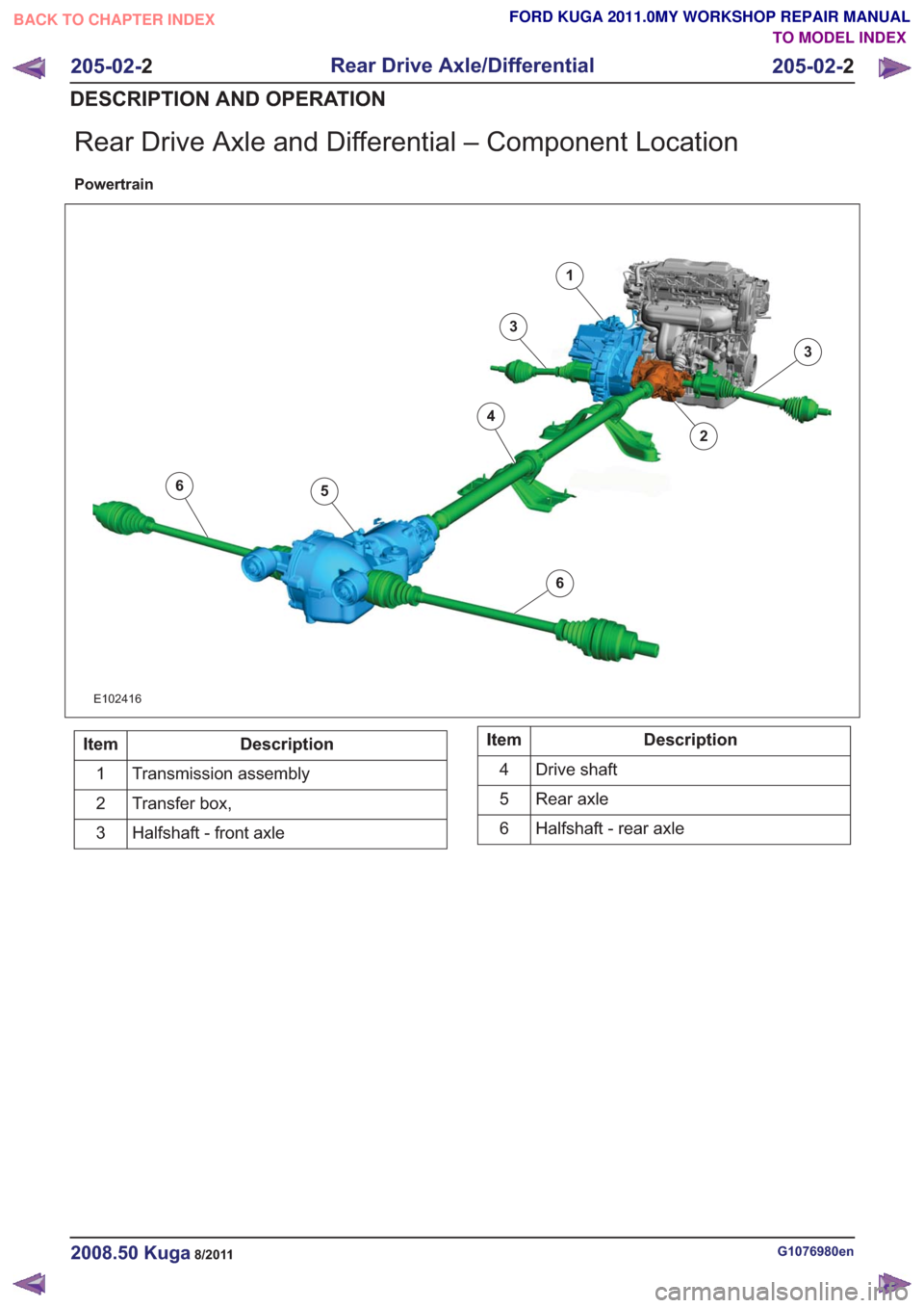
Rear Drive Axle and Differential – Component Location
Powertrain
6
6
1
2
3
3
4
5
6
6
E102416
Description
Item
Transmission assembly
1
Transfer box,
2
Halfshaft - front axle
3Description
Item
Drive shaft
4
Rear axle
5
Halfshaft - rear axle
6
G1076980en2008.50 Kuga8/2011
205-02- 2
Rear Drive Axle/Differential
205-02- 2
DESCRIPTION AND OPERATION
TO MODEL INDEX
BACK TO CHAPTER INDEX
FORD KUGA 2011.0MY WORKSHOP REPAIR MANUAL
Page 1252 of 2057
General overview
Haldex clutches of the 3rd and 4th generations are
used in the Ford Kuga.
The development of the third generation Haldex
clutch represents a big step forward in modern
all-wheel technology. The Haldex clutch is
electro-hydraulically controlled. Additional
information is taken into consideration during
control tasks via the all-wheel drive control unit.
Slip alone is no longer decisive for the distribution
of the propulsive forces; the vehicle's driving
dynamics are also taken into consideration. The
control unit accesses the driving-related data via
the data bus. With this data, the control unit has
all the essential information about speed, cornering,
coasting or traction operation, and can optimally
react to every driving situation.
Compared with the previous generation, the 4th
generation Haldex clutches operate with higher
pressure and achieve shorter response times when
distributing the drive forces.
Advantages of the Haldex clutch:
• Permanent all-wheel drive withelectronically-controlled multi-plate clutch
• Fast response
• No straining when parking and manoeuvring
• Compatible with different tyres (e.g. emergency spare wheel)
• Fully combinable with driving dynamic control systems
The driveshaft is connected to the input shaft of
the Haldex clutch. Within the Haldex clutch, the
input shaft is separated from the output shaft to
the rear axle differential by means of a multi-plate
clutch. Torque is only transmitted to the rear axle
differential when the plate assembly of the Haldex
clutch is closed.
The multi-plate clutch is electro-hydraulically
controlled via the all-wheel drive control unit. For
ecological driving, the torque to the rear axle is reduced to a minimum up to a throttle position of
approx. 50%. A prerequisite for this is that there is
no difference in speed in the Haldex clutch between
the input and output shafts.
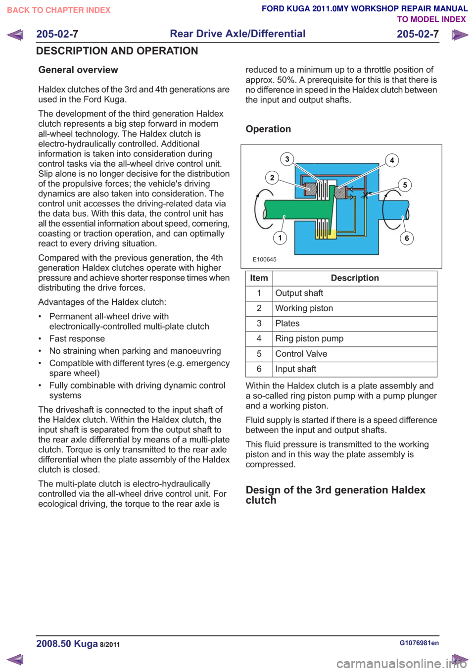
Operation
E100645
16
3
25
4
Description
Item
Output shaft
1
Working piston
2
Plates
3
Ring piston pump
4
Control Valve
5
Input shaft
6
Within the Haldex clutch is a plate assembly and
a so-called ring piston pump with a pump plunger
and a working piston.
Fluid supply is started if there is a speed difference
between the input and output shafts.
This fluid pressure is transmitted to the working
piston and in this way the plate assembly is
compressed.
Design of the 3rd generation Haldex
clutch
G1076981en2008.50 Kuga8/2011
205-02- 7
Rear Drive Axle/Differential
205-02- 7
DESCRIPTION AND OPERATION
TO MODEL INDEX
BACK TO CHAPTER INDEX
FORD KUGA 2011.0MY WORKSHOP REPAIR MANUAL
Page 1254 of 2057
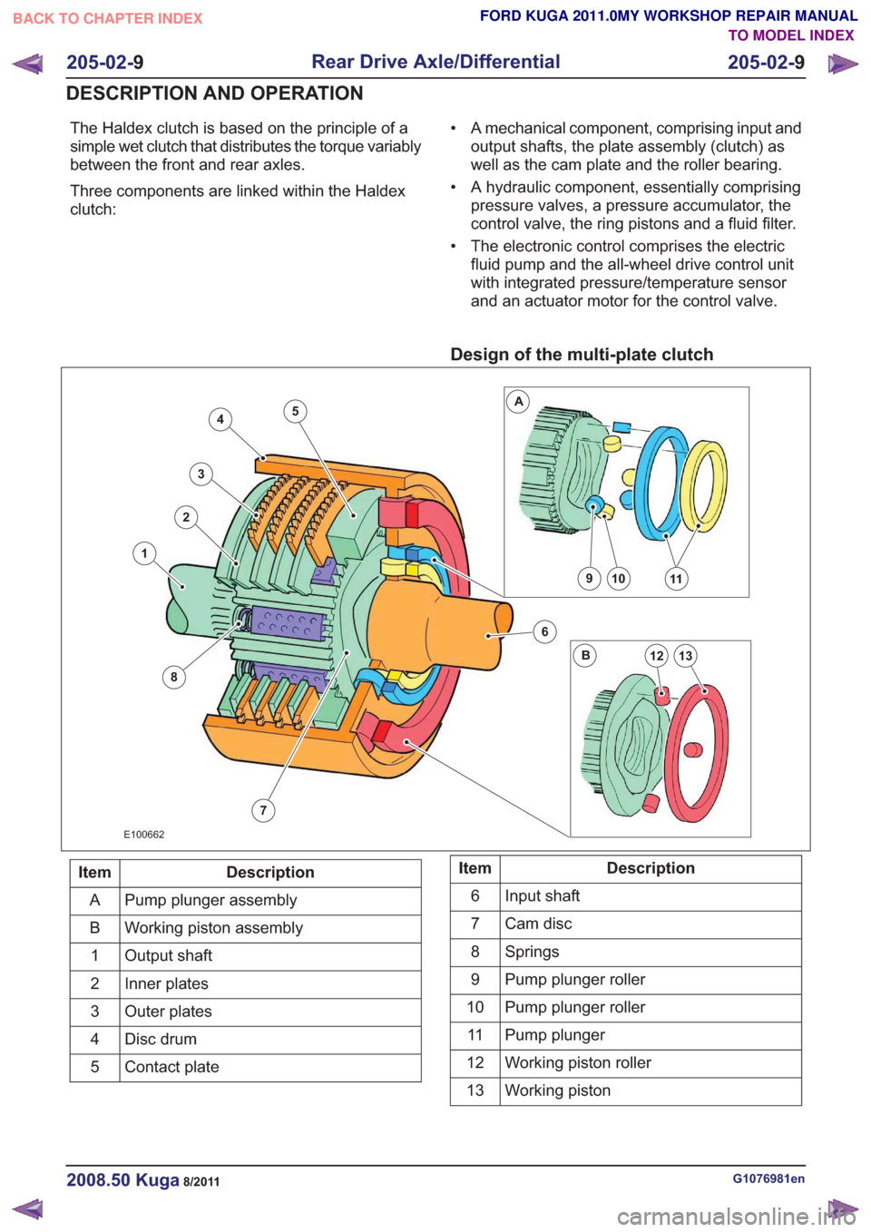
The Haldex clutch is based on the principle of a
simple wet clutch that distributes the torque variably
between the front and rear axles.
Three components are linked within the Haldex
clutch:• A mechanical component, comprising input and
output shafts, the plate assembly (clutch) as
well as the cam plate and the roller bearing.
• A hydraulic component, essentially comprising pressure valves, a pressure accumulator, the
control valve, the ring pistons and a fluid filter.
• The electronic control comprises the electric fluid pump and the all-wheel drive control unit
with integrated pressure/temperature sensor
and an actuator motor for the control valve.
Design of the multi-plate clutch
7
4
3
2
8
1
6
10911
13
A
B12
5
E100662
Description
Item
Pump plunger assembly
A
Working piston assembly
B
Output shaft
1
Inner plates
2
Outer plates
3
Disc drum
4
Contact plate
5Description
Item
Input shaft
6
Cam disc
7
Springs
8
Pump plunger roller
9
Pump plunger roller
10
Pump plunger
11
Working piston roller
12
Working piston
13
G1076981en2008.50 Kuga8/2011
205-02- 9
Rear Drive Axle/Differential
205-02- 9
DESCRIPTION AND OPERATION
TO MODEL INDEX
BACK TO CHAPTER INDEX
FORD KUGA 2011.0MY WORKSHOP REPAIR MANUAL