Page 1458 of 2057

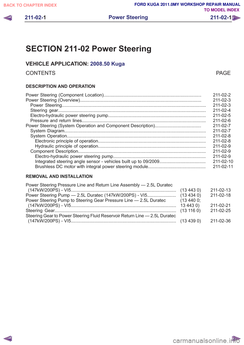
SECTION 211-02 Power Steering
VEHICLE APPLICATION:2008.50 Kuga
PA G E
CONTENTS
DESCRIPTION AND OPERATION
211-02-2
Power Steering (Component Location) ........................................................................\
......
211-02-3
Power Steering (Overview) ........................................................................\
.........................
211-02-3
Power Steering ........................................................................\
...........................................
211-02-4
Steering gear ........................................................................\
..............................................
211-02-5
Electro-hydraulic power steering pump ........................................................................\
......
211-02-6
Pressure and return lines ........................................................................\
...........................
211-02-7
Power Steering (System Operation and Component Description) .....................................
211-02-7
System Diagram ........................................................................\
.........................................
211-02-8
System Operation ........................................................................\
.......................................
211-02-8
Electronic principle of operation ........................................................................\
..............
211-02-9
Hydraulic principle of operation ........................................................................\
..............
211-02-9
Component Description ........................................................................\
..............................
211-02-9
Electro-hydraulic power steering pump ........................................................................\
..
211-02-10
Integrated steering angle sensor - vehicles built up to 09/2009 .....................................
211-02-11
Brushless DC motor with integral power steering module..............................................
REMOVAL AND INSTALLATION
211-02-13
(13 443 0)
Power Steering Pressure Line and Return Line Assembly — 2.5L Duratec
(147kW/200PS) - VI5 ........................................................................\
............
211-02-18
(13 434 0)
Power Steering Pump — 2.5L Duratec (147kW/200PS) - VI5 .......................
211-02-21
(13 440 0;
13 443 0)
Power Steering Pump to Steering Gear Pressure Line — 2.5L Duratec
(147kW/200PS) - VI5 ........................................................................\
............
211-02-25
(13 116 0)
Steering Gear ........................................................................\
.........................
211-02-36
(13 439 0)
Steering Gear to Power Steering Fluid Reservoir Return Line — 2.5L Duratec
(147kW/200PS) - VI5 ........................................................................\
............
211-02-1
Power Steering
211-02- 1
.
TO MODEL INDEX
BACK TO CHAPTER INDEX
FORD KUGA 2011.0MY WORKSHOP REPAIR MANUAL
Page 1470 of 2057
Power Steering Pressure Line and Return Line Assembly — 2.5LDuratec (147kW/200PS) - VI5(13 443 0)
General Equipment
Hose Clamp Remover/Installer
Removal
NOTE: Removal steps in this procedure may
contain installation details.
1. Refer to: Steering System Health and Safety
Precautions (100-00 General Information,
Description and Operation).
2. Refer to: Wheel and Tire (204-04 Wheels and
Tires, Removal and Installation).
3.
E98543
x7
4.
E99630
5.
E99631
6. WARNING: Be prepared to collect escaping fluid.
1. General Equipment: Hose ClampRemover/Installer
2. Torque: 30
Nm
E114706
1
2
7. Torque: 23Nm1.
2. Torque: 7
Nm
G1185534en2008.50 Kuga8/2011
211-02- 13
Power Steering
211-02- 13
REMOVAL AND INSTALLATION
TO MODEL INDEX
BACK TO CHAPTER INDEX
FORD KUGA 2011.0MY WORKSHOP REPAIR MANUAL
Page 1535 of 2057
DISASSEMBLY303-01-84
(21 134 8)
Engine ........................................................................\
....................................
DISASSEMBLY AND ASSEMBLY OF SUBASSEMBLIES 303-01-93
(21 165 6)
Cylinder Head ........................................................................\
.........................
ASSEMBLY 303-01-94
(21 134 8)
Engine ........................................................................\
....................................
INSTALLATION 303-01-112
(21 139 4)
Engine Accessories ........................................................................\
................
303-01-119
(21 132 0;
21 132 6;
21 132 7)
Engine — Vehicles With: 5-Speed Automatic Transaxle (AW55)
...................
303-01-2
Engine— 2.5L Duratec (147kW/200PS) - VI5303-01-
2
.
TO MODEL INDEX
BACK TO CHAPTER INDEX
PAGE 2 OF 2 FORD KUGA 2011.0MY WORKSHOP REPAIR MANUAL
Page 1549 of 2057

Engine – System Operation and Component Description
System Operation
The variable camshaft timing occurs
electro-hydraulically and individually for both
camshafts.
The camshaft adjusters work according to the vane
cell principle and have an adjustment range of 52°
crank angle on the intake side and 47° crank angle
on the exhaust side. On starting the engine and
during idling, both camshafts are mechanically
locked in their starting positions. The exhaust
camshaft is in the early position and the intake
camshaft is in the late position. The camshaftadjuster on the exhaust side has a torsion spring
which compensates the camshaft drive torque.
This ensures that the assembly can return to the
starting position under all operating conditions and
when the engine is turned off.
Internal exhaust gas recirculation can be realized
through continuous adjustment of the timings. This
results in better fuel consumption and more
favorable combustion temperatures which produce
less pollutants. This means that pollutant level IV
can be adhered to with a 3-way catalytic converter.
The variable timings also make it possible to
optimize performance with wide open throttle.
G1032416en2008.50 Kuga8/2011
303-01-
16
Engine— 2.5L Duratec (147kW/200PS) - VI5303-01-
16
DESCRIPTION AND OPERATION
TO MODEL INDEX
BACK TO CHAPTER INDEX
FORD KUGA 2011.0MY WORKSHOP REPAIR MANUAL
Page 1608 of 2057
E112535
1
2
62.General Equipment: Cable Ties
E112536
63. WARNING: Make sure that the engine
and transmission assembly is on
wooden blocks and secured with
suitable retaining straps.
General Equipment: Retaining Strap
General Equipment: Mounting Table Set
General Equipment: Wooden Block
G1191240en2008.50 Kuga8/2011
303-01- 75
Engine— 2.5L Duratec (147kW/200PS) - VI5303-01-
75
REMOVAL
TO MODEL INDEX
BACK TO CHAPTER INDEX
FORD KUGA 2011.0MY WORKSHOP REPAIR MANUAL
Page 1617 of 2057
Engine(21 134 8)
Disassembly
Special Tool(s) / General Equipment211-014
Remover, Steering Wheel
13019
303-1054
Locking Tool, Timing Belt
Tensioner
3031054
Punch
Two Leg Puller
1.
E68416
2.
E122374
x4
3. General Equipment: Two Leg Puller
E122375
Vehicles with mechanical timing belt tensioner
4.
E68488
1
3
2
G543498en2008.50 Kuga8/2011
303-01- 84
Engine— 2.5L Duratec (147kW/200PS) - VI5303-01-
84
DISASSEMBLY
TO MODEL INDEX
BACK TO CHAPTER INDEX
FORD KUGA 2011.0MY WORKSHOP REPAIR MANUAL
Page 1618 of 2057
Vehicles with automatic timing belt tensioner
5. WARNING: Take extra care whenhandling the compressed spring.
6. WARNING: Take extra care whenhandling the compressed spring.
All vehicles
7.
G543498en2008.50 Kuga8/2011
303-01- 85
Engine— 2.5L Duratec (147kW/200PS) - VI5303-01-
85
DISASSEMBLY
TO MODEL INDEX
BACK TO CHAPTER INDEX
FORD KUGA 2011.0MY WORKSHOP REPAIR MANUAL
Install the Special Tool(s): 303-1054
1
2
E113799
303-1054
Special Tool(s): 303-1054
E113800
1
2
3
303-1054
E68408
1
2
8.
E68490
1
2
Page 1619 of 2057
G543498en2008.50 Kuga8/2011
E68749
TO MODEL INDEX
BACK TO CHAPTER INDEX
FORD KUGA 2011.0MY WORKSHOP REPAIR MANUAL
E69625
211-014
E68745
E74333
9.
10.
x2
11 .
Special Tool(s): 211-014
x7
12.
303-01- 86
Engine— 2.5L Duratec (147kW/200PS) - VI5303-01-
86
DISASSEMBLY
E65076
13.
E68491
14.