Page 1293 of 2057
24. CAUTION: Make sure that theinstallation marks are aligned.
1. Torque: 35Nm
2. Torque: 35Nm
3. Torque: 35Nm
3
x2
2
1
2
1
x3
3
x2
2
1
2
1
x3
E101042
25.Torque: 25Nm
x2
x2
x2
x2
x2
x2
E114188
G1268328en2008.50 Kuga8/2011
205-02- 48
Rear Drive Axle/Differential
205-02- 48
DISASSEMBLY AND ASSEMBLY
TO MODEL INDEX
BACK TO CHAPTER INDEX
FORD KUGA 2011.0MY WORKSHOP REPAIR MANUAL
Page 1294 of 2057
26.Torque:
• Stage 1: 35
Nm
• Stage 2: Loosen 360°
• Stage 3: 85Nm
E114375
27.
E98543
x7
28. N O T E : Make sure that a new component is
installed.
1.
2. Material: Transmission Oil AWD
(8U7J-8708687-AA) transmission fluid
2
1
2
1
E124780
29.
E128367
30.Torque: 6Nm
x2x2
E124749
31.Material: Transmission Oil AWD
(8U7J-8708687-AA) transmission fluid
E124750
G1268328en2008.50 Kuga8/2011
205-02- 49
Rear Drive Axle/Differential
205-02- 49
DISASSEMBLY AND ASSEMBLY
TO MODEL INDEX
BACK TO CHAPTER INDEX
FORD KUGA 2011.0MY WORKSHOP REPAIR MANUAL
Page 1295 of 2057
32.Torque: 6Nm
E124748
33.
E114257
34.Refer to: Active On-Demand Coupling Fluid
Level Check (205-02 Rear Drive
Axle/Differential, General Procedures).
35. Lower the vehicle.
G1268328en2008.50 Kuga8/2011
205-02- 50
Rear Drive Axle/Differential
205-02- 50
DISASSEMBLY AND ASSEMBLY
TO MODEL INDEX
BACK TO CHAPTER INDEX
FORD KUGA 2011.0MY WORKSHOP REPAIR MANUAL
Page 1298 of 2057

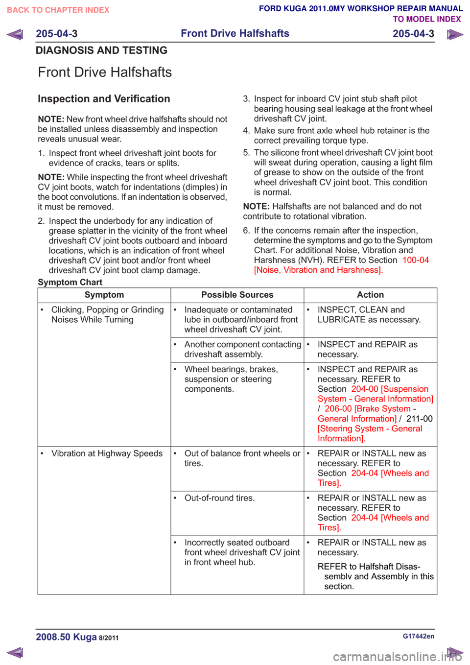
Front Drive Halfshafts
Inspection and Verification
NOTE:New front wheel drive halfshafts should not
be installed unless disassembly and inspection
reveals unusual wear.
1. Inspect front wheel driveshaft joint boots for evidence of cracks, tears or splits.
NOTE: While inspecting the front wheel driveshaft
CV joint boots, watch for indentations (dimples) in
the boot convolutions. If an indentation is observed,
it must be removed.
2. Inspect the underbody for any indication of grease splatter in the vicinity of the front wheel
driveshaft CV joint boots outboard and inboard
locations, which is an indication of front wheel
driveshaft CV joint boot and/or front wheel
driveshaft CV joint boot clamp damage. 3. Inspect for inboard CV joint stub shaft pilot
bearing housing seal leakage at the front wheel
driveshaft CV joint.
4. Make sure front axle wheel hub retainer is the correct prevailing torque type.
5. The silicone front wheel driveshaft CV joint boot will sweat during operation, causing a light film
of grease to show on the outside of the front
wheel driveshaft CV joint boot. This condition
is normal.
NOTE: Halfshafts are not balanced and do not
contribute to rotational vibration.
6. If the concerns remain after the inspection, determine the symptoms and go to the Symptom
Chart. For additional Noise, Vibration and
Harshness (NVH). REFER to Section 100-04
[Noise, Vibration and Harshness] .
Symptom Chart
Action
Possible Sources
Symptom
• INSPECT, CLEAN andLUBRICATE as necessary.
• Inadequate or contaminated
lube in outboard/inboard front
wheel driveshaft CV joint.
• Clicking, Popping or Grinding
Noises While Turning
• INSPECT and REPAIR asnecessary.
• Another component contacting
driveshaft assembly.
• INSPECT and REPAIR asnecessary. REFER to
Section 204-00 [Suspension
System - General Information]
/ 206-00 [Brake System -
General Information] /211-00
[Steering System - General
Information] .
• Wheel bearings, brakes,
suspension or steering
components.
• REPAIR or INSTALL new asnecessary. REFER to
Section 204-04 [Wheels and
Tires] .
• Out of balance front wheels or
tires.
• Vibration at Highway Speeds
• REPAIR or INSTALL new asnecessary. REFER to
Section 204-04 [Wheels and
Tires] .
• Out-of-round tires.
• REPAIR or INSTALL new asnecessary.
REFER to Halfshaft Disas-
semblv and Assembly in this
section.
• Incorrectly seated outboard
front wheel driveshaft CV joint
in front wheel hub.
G17442en2008.50 Kuga8/2011
205-04- 3
Front Drive Halfshafts
205-04- 3
DIAGNOSIS AND TESTING
TO MODEL INDEX
BACK TO CHAPTER INDEX
FORD KUGA 2011.0MY WORKSHOP REPAIR MANUAL
Page 1299 of 2057

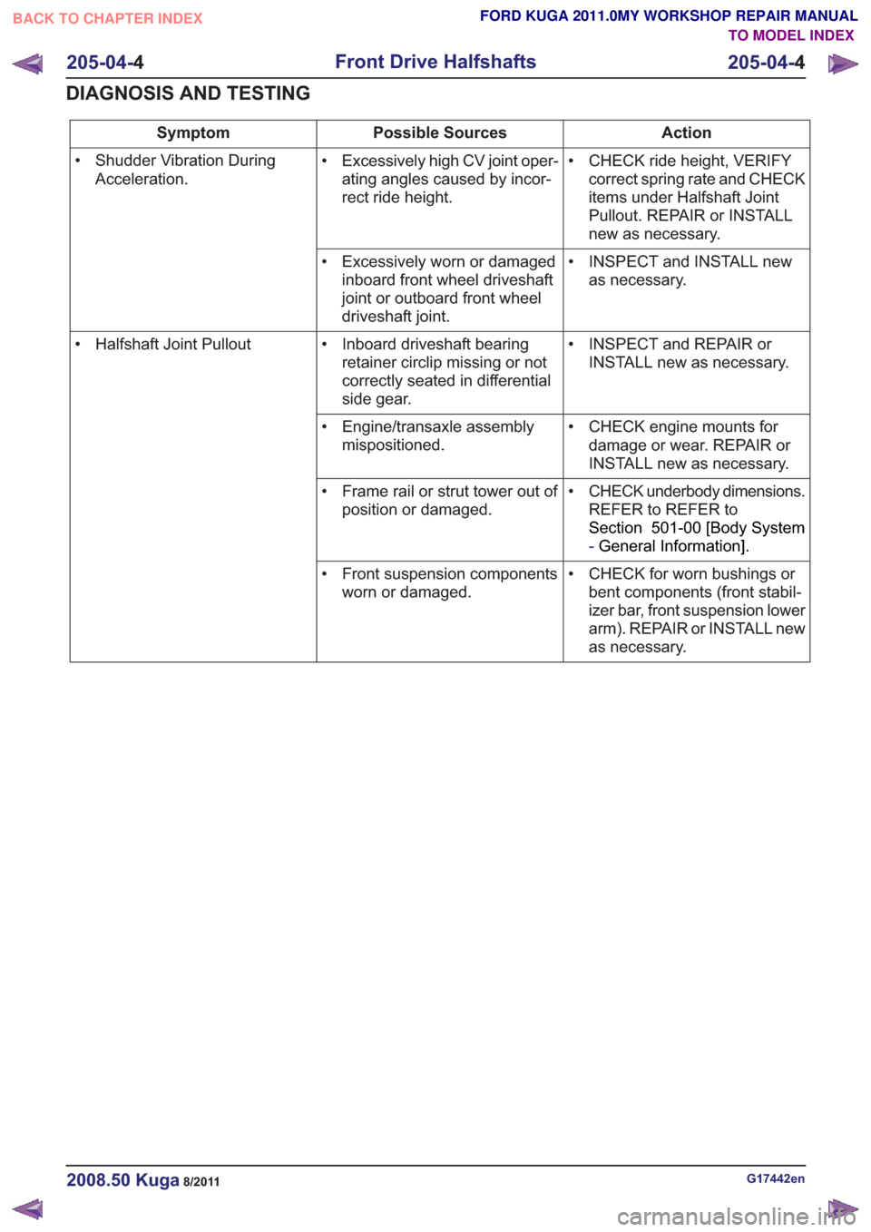
Action
Possible Sources
Symptom
• CHECK ride height, VERIFYcorrect spring rate and CHECK
items under Halfshaft Joint
Pullout. REPAIR or INSTALL
new as necessary.
• Excessively high CV joint oper-
ating angles caused by incor-
rect ride height.
• Shudder Vibration During
Acceleration.
• INSPECT and INSTALL newas necessary.
• Excessively worn or damaged
inboard front wheel driveshaft
joint or outboard front wheel
driveshaft joint.
• INSPECT and REPAIR orINSTALL new as necessary.
• Inboard driveshaft bearing
retainer circlip missing or not
correctly seated in differential
side gear.
• Halfshaft Joint Pullout
• CHECK engine mounts fordamage or wear. REPAIR or
INSTALL new as necessary.
• Engine/transaxle assembly
mispositioned.
• CHECK underbody dimensions.REFER to REFER to
Section 501-00 [Body System
-General Information] .
• Frame rail or strut tower out of
position or damaged.
• CHECK for worn bushings orbent components (front stabil-
izer bar, front suspension lower
arm). REPAIR or INSTALL new
as necessary.
• Front suspension components
worn or damaged.
G17442en2008.50 Kuga8/2011
205-04- 4
Front Drive Halfshafts
205-04- 4
DIAGNOSIS AND TESTING
TO MODEL INDEX
BACK TO CHAPTER INDEX
FORD KUGA 2011.0MY WORKSHOP REPAIR MANUAL
Page 1355 of 2057

too close to the fluid level indicator assembly,
or float assembly damage.
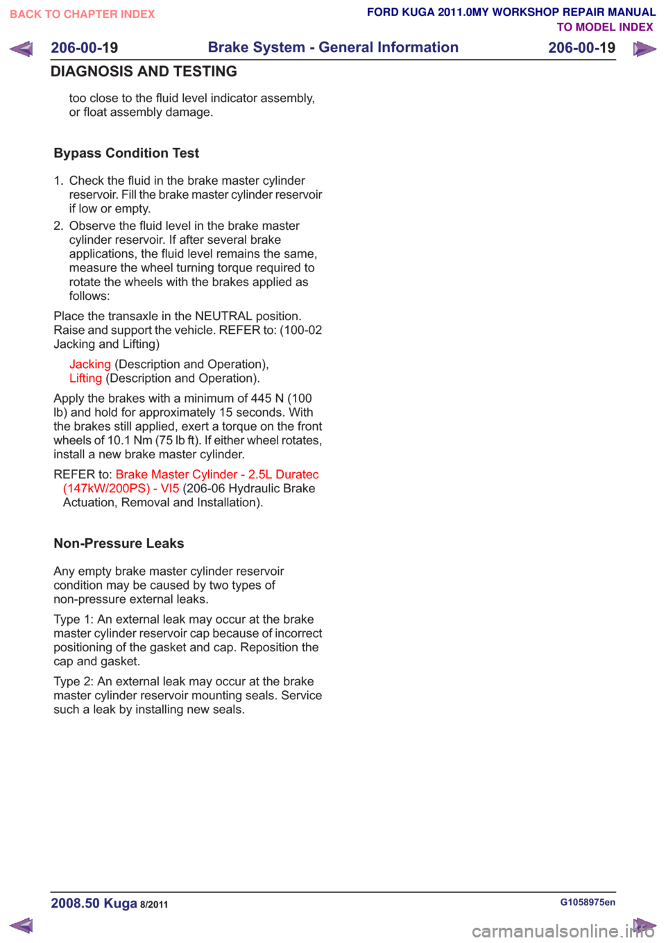
Bypass Condition Test
1. Check the fluid in the brake master cylinderreservoir. Fill the brake master cylinder reservoir
if low or empty.
2. Observe the fluid level in the brake master cylinder reservoir. If after several brake
applications, the fluid level remains the same,
measure the wheel turning torque required to
rotate the wheels with the brakes applied as
follows:
Place the transaxle in the NEUTRAL position.
Raise and support the vehicle. REFER to: (100-02
Jacking and Lifting) Jacking (Description and Operation),
Lifting (Description and Operation).
Apply the brakes with a minimum of 445 N (100
lb) and hold for approximately 15 seconds. With
the brakes still applied, exert a torque on the front
wheels of 10.1 Nm (75 lb ft). If either wheel rotates,
install a new brake master cylinder.
REFER to: Brake Master Cylinder - 2.5L Duratec
(147kW/200PS) - VI5 (206-06 Hydraulic Brake
Actuation, Removal and Installation).
Non-Pressure Leaks
Any empty brake master cylinder reservoir
condition may be caused by two types of
non-pressure external leaks.
Type 1: An external leak may occur at the brake
master cylinder reservoir cap because of incorrect
positioning of the gasket and cap. Reposition the
cap and gasket.
Type 2: An external leak may occur at the brake
master cylinder reservoir mounting seals. Service
such a leak by installing new seals.
G1058975en2008.50 Kuga8/2011
206-00- 19
Brake System - General Information
206-00- 19
DIAGNOSIS AND TESTING
TO MODEL INDEX
BACK TO CHAPTER INDEX
FORD KUGA 2011.0MY WORKSHOP REPAIR MANUAL
Page 1391 of 2057
DETAILS/RESULTS/ACTIONS
TEST CONDITIONS
B4: CHECK REAR PARKING BRAKE CABLES
1 Disconnect the parking brake at the rear brakes,
one at a time.
– Rotate the wheel affected by the disconnected parking brake.
• Did the wheel turn freely?
zYe s INSTALL a new parking brake control lever
on the rear drum brakes or caliper assembly
on rear disc brakes.
REFER to: Parking Brake Control (206-05
Parking Brake and Actuation, Removal and
Installation)
/ Brake Caliper (206-04 Rear Disc Brake,
Removal and Installation).
TEST the system for normal operation.
zNo
REFER to: Brake System (206-00 Brake
System - General Information, Diagnosis
and Testing).
G1063696en2008.50 Kuga8/2011
206-05- 8
Parking Brake and Actuation
206-05- 8
DIAGNOSIS AND TESTING
TO MODEL INDEX
BACK TO CHAPTER INDEX
FORD KUGA 2011.0MY WORKSHOP REPAIR MANUAL
Page 1422 of 2057

Description
Item
Front wheel sensor, right-hand side
8Description
Item
9 ESP switch
Testing the brakes on a roller dynamometer
- 4X4 vehicles only
On 4X4 vehicles a brake test on a roller
dynamometer must only be performed under the
following conditions.
• The brake test must not exceed a duration of 1 minute.
• Ignition key in position 0.
• The roller speed must not exceed 5 km/h.
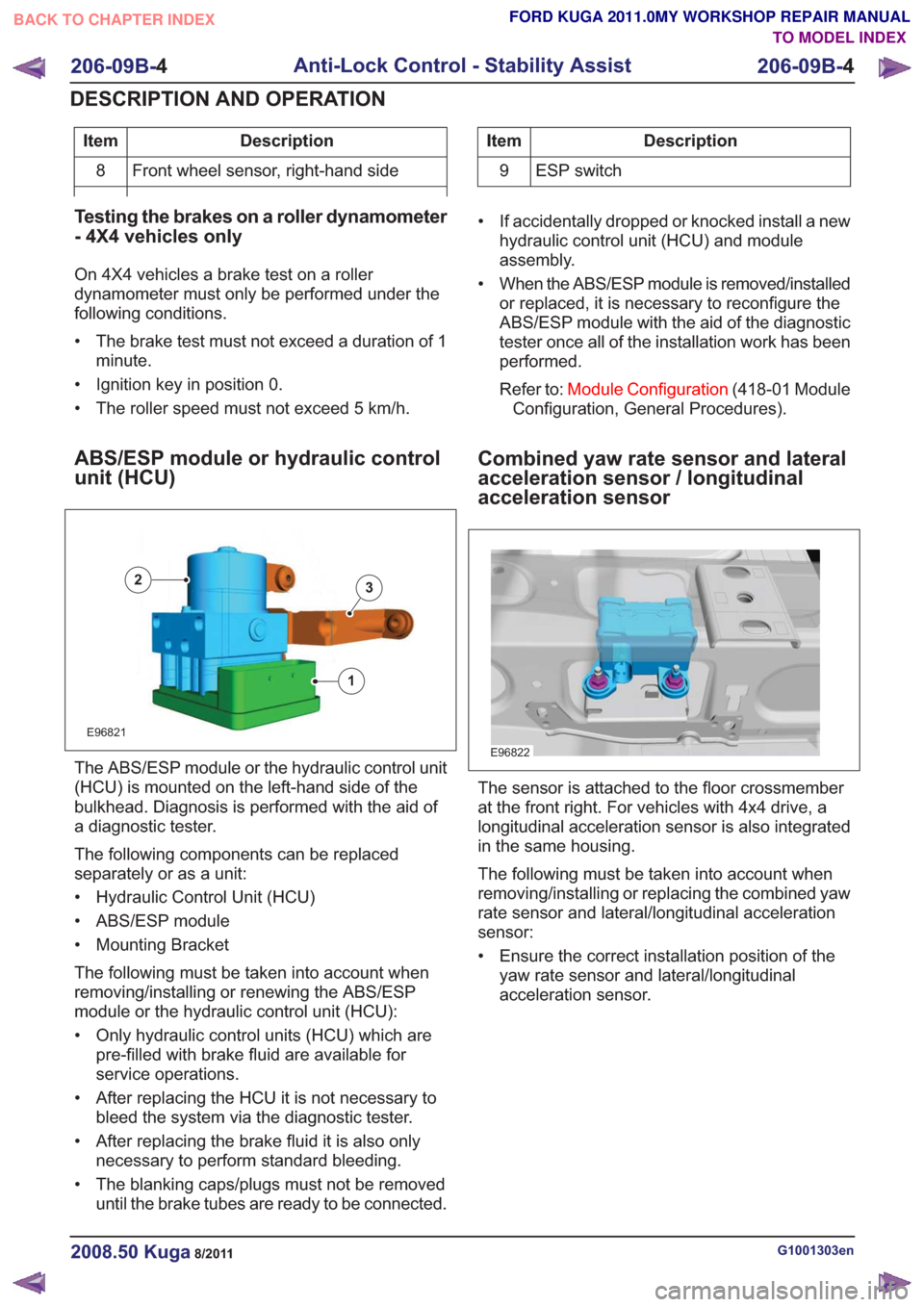
ABS/ESP module or hydraulic control
unit (HCU)
E96821
1
23
The ABS/ESP module or the hydraulic control unit
(HCU) is mounted on the left-hand side of the
bulkhead. Diagnosis is performed with the aid of
a diagnostic tester.
The following components can be replaced
separately or as a unit:
• Hydraulic Control Unit (HCU)
• ABS/ESP module
• Mounting Bracket
The following must be taken into account when
removing/installing or renewing the ABS/ESP
module or the hydraulic control unit (HCU):
• Only hydraulic control units (HCU) which are pre-filled with brake fluid are available for
service operations.
• After replacing the HCU it is not necessary to bleed the system via the diagnostic tester.
• After replacing the brake fluid it is also only necessary to perform standard bleeding.
• The blanking caps/plugs must not be removed until the brake tubes are ready to be connected. • If accidentally dropped or knocked install a new
hydraulic control unit (HCU) and module
assembly.
• When the ABS/ESP module is removed/installed or replaced, it is necessary to reconfigure the
ABS/ESP module with the aid of the diagnostic
tester once all of the installation work has been
performed.
Refer to: Module Configuration (418-01 Module
Configuration, General Procedures).
Combined yaw rate sensor and lateral
acceleration sensor / longitudinal
acceleration sensor
E96822
The sensor is attached to the floor crossmember
at the front right. For vehicles with 4x4 drive, a
longitudinal acceleration sensor is also integrated
in the same housing.
The following must be taken into account when
removing/installing or replacing the combined yaw
rate sensor and lateral/longitudinal acceleration
sensor:
• Ensure the correct installation position of the yaw rate sensor and lateral/longitudinal
acceleration sensor.
G1001303en2008.50 Kuga8/2011
206-09B- 4
Anti-Lock Control - Stability Assist
206-09B- 4
DESCRIPTION AND OPERATION
TO MODEL INDEX
BACK TO CHAPTER INDEX
FORD KUGA 2011.0MY WORKSHOP REPAIR MANUAL