2011 FORD KUGA display
[x] Cancel search: displayPage 304 of 2057
Description
Item
In-car entertainment
1
Genetic electronic module (GEM).
2
instrument cluster
3
ABS4
ABS sensor assembly
5
Rear LH mid/bass range speaker
6
Rear RH mid/bass range speaker
7
Rear LH tweeter
8 Description
Item
Rear RH tweeter
9
AUX port
10
Radio remote control.
11
FM/AM antenna
12
Front LH mid/bass speaker
13
Front RH mid/bass speaker
14
Front LH tweeter
15
Front RH tweeter
16
System Operation
In-car entertainment
The audio system is connected to the MS CAN
network and uses an internal amplifier which
directly drives the system speakers. It can only be
operated via the head unit and the radio remote
control. The head unit is connected to the vehicle
on the medium speed CAN bus. This allows the
unit to be interrogated for diagnostic purposes.
The automatic volume control (AVC) adjusts the
audio volume depending on the driving speed. The
audio device receives the necessary signals for
the ABS (anti-lock brake system) wheel sensors
from the instrument cluster on the MS-CAN. As
vehicle speed increases the audio level is adjusted
to compensate for extra road and vehicle noise.
Eight AVC settings are possible.
To choose the setting for automatic volume control,
press the MENU button until the AVC display
appears.
The required adjustment level is determined by the
Infotainment control unit based on the driving
speed signal. The vehicle speed signal is received
over the CAN. The signal is an average of the four
wheel speed sensor signals. Should an invalid
speed signal be received the AVC will not alter the
output volume.
AVC is controlled by the audio amplifier. Component Description
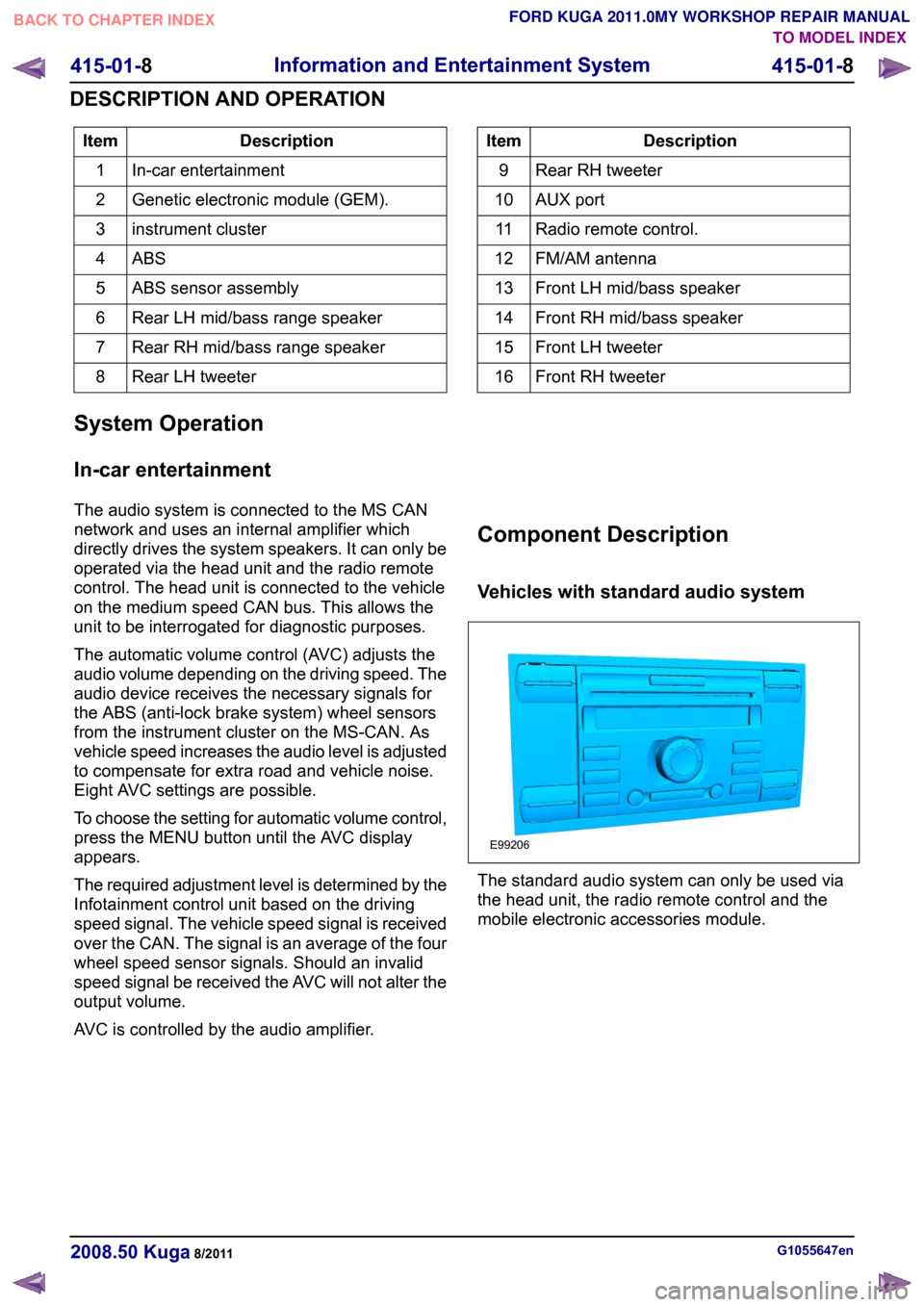
Vehicles with standard audio system
The standard audio system can only be used via
the head unit, the radio remote control and the
mobile electronic accessories module.
G1055647en
2008.50 Kuga 8/2011 415-01-8
Information and Entertainment System
415-01-8
DESCRIPTION AND OPERATIONTO MODEL INDEX
BACK TO CHAPTER INDEX
FORD KUGA 2011.0MY WORKSHOP REPAIR MANUALE99206
Page 305 of 2057
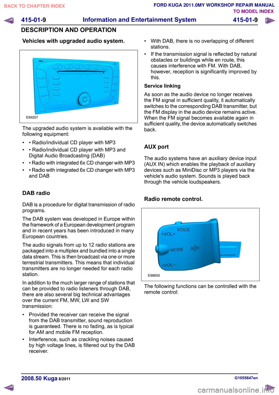
Vehicles with upgraded audio system.
The upgraded audio system is available with the
following equipment:
• • Radio/individual CD player with MP3
• • Radio/individual CD player with MP3 and
Digital Audio Broadcasting (DAB)
• • Radio with integrated 6x CD changer with MP3
• • Radio with integrated 6x CD changer with MP3
and DAB
DAB radio
DAB is a procedure for digital transmission of radio
programs.
The DAB system was developed in Europe within
the framework of a European development program
and in recent years has been introduced in many
European countries.
The audio signals from up to 12 radio stations are
packaged into a multiplex and bundled into a single
data stream. This is then broadcast via one or more
terrestrial transmitters. This means that individual
transmitters are no longer needed for each radio
station.
In addition to the much larger range of stations that
can be provided to radio listeners through DAB,
there are also several big technical advantages
over the current FM, MW, LW and SW
transmission:
• Provided the receiver can receive the signal from the DAB transmitter, sound reproduction
is guaranteed. There is no fading, as is typical
for AM and mobile FM reception.
• Interference, such as crackling noises caused by high voltage lines, is filtered out by the DAB
receiver. • With DAB, there is no overlapping of different
stations.
• If the transmission signal is reflected by natural obstacles or buildings while en route, this
causes interference with FM. With DAB,
however, reception is significantly improved by
this.
Service linking
As soon as the audio device no longer receives
the FM signal in sufficient quality, it automatically
switches to the corresponding DAB transmitter, but
the FM display in the audio device remains active.
When the FM signal becomes available again in
sufficient quality, the device automatically switches
back.
AUX port
The audio systems have an auxiliary device input
(AUX IN) which enables the playback of auxiliary
devices such as MiniDisc or MP3 players via the
vehicle's audio system. Sounds is played back
through the vehicle loudspeakers.
Radio remote control. The following functions can be controlled with the
remote control:
G1055647en
2008.50 Kuga 8/2011 415-01-9
Information and Entertainment System
415-01-9
DESCRIPTION AND OPERATIONTO MODEL INDEX
BACK TO CHAPTER INDEX
FORD KUGA 2011.0MY WORKSHOP REPAIR MANUALE99207 E98650
Page 357 of 2057

Visual Inspection
Electrical
• Fuse(s)
• Lamp(s)
• Bulb(s)
• Connector(s)
• Switches
• Relay
• Wiring harness
3. Resolve any obvious causes or concerns found during the visual inspection before carrying out
any further tests.
4. If the concern persists after the visual inspection, PERFORM a fault diagnosis with
the Ford approved diagnostic tool and RECTIFY
any displayed faults in accordance with the
displayed fault description. CHECK the
operation of the system. G1055008en
2008.50 Kuga 8/2011 417-01-23
Exterior Lighting
417-01-23
DIAGNOSIS AND TESTINGTO MODEL INDEX
BACK TO CHAPTER INDEX
FORD KUGA 2011.0MY WORKSHOP REPAIR MANUAL
Page 383 of 2057

Description
Item
Medium speed CAN (controller area
network) bus (MS-CAN)
A
High speed CAN bus (HS-CAN)
B
LIN (local interconnect network) bus
C
Terminating resistors
Drive
DLC (data link connector)
E
GEMRefer to Component Description: ABS
(page ?)
1
Fuel fired booster heater /programmable
fuel fired booster heater
2
The EATC control module
3
Reversing camera module (RVC)
4
Parking aid module (PAM)
5
DDM6
Front driver's side switch unit
7
Driver's side RDM
8
PDM (Passenger Door Module)
9
Passenger side RDM
10
Audio unit/navigation unit
11
CD changer
12 Description
Item
Navigation system module - vehicles
equipped with DVD navigation system with
touch screen (not communicating with the
diagnostic unit)
13
Navigation system display - vehicles
equipped with DVD navigation system with
touch screen (not communicating with the
diagnostic unit)
14
Control module for electronic auxiliary
equipment (BVC)
15
RCM16
Keyless vehicle module (KVM)
17
Instrument Cluster
18
PCM19
Fuel additive system module.
20
ABS module or electronic stability program
module
21
Yaw rate sensor/lateral acceleration
sensor
22
Headlamp Leveling Module
23
All-wheel drive control unit
24
Electrohydraulic power steering module
25
System Operation
General
In a communications network (data bus system),
various modules of different systems are connected
to one another via one or several lines.
The data bus system is used exclusively for
transmitting data between the connected modules,
as well as between the connected modules and
the Ford diagnostic unit.
In a data bus system, complete data blocks are
transmitted instead of single on/off pulses. In
addition to the actual information, these data blocks
also contain data regarding the address of the
module to be addressed, the size of the data block
and information for monitoring the content of each
individual data block.
Data bus systems offer various advantages: • Simplified data transmission between the
modules due to a standardized protocol
• Fewer sensors and connectors
• Improved diagnostic options
• Lower costs
The DLC is connected to the various data bus
systems and to the power supply via the standard
16-pin GEM. The signal for the module
programming is also transferred via the DLC.
In a data bus system, if there is a break in one or
both lines or there is a short to ground or to voltage,
then communication between the modules and
with the Ford diagnostic unit is disturbed or is no
longer possible at all.
In order to be able to establish communication with
one another, the modules of the individual systems G1030779en
2008.50 Kuga 8/2011 418-00-6
Module Communications Network
418-00-6
DESCRIPTION AND OPERATIONTO MODEL INDEX
BACK TO CHAPTER INDEX
FORD KUGA 2011.0MY WORKSHOP REPAIR MANUAL
Page 389 of 2057

Programmable Module Installation
Activation
5.
Install the most up-to-date software version in
IDS.
6. If, before replacing a module, it was not possible
to read out the vehicle-specific data using the
integrated diagnostic system (IDS) (the module
to be replaced does not respond) then, during
programming of the new module, the
vehicle-specific data must be entered manually
via a selection list in IDS or via a code which
can be obtained from the Technical Hotline.
7. In order to program, select the "Install
programmable module" submenu in the "Module
programming" menu tool box and then follow
the instructions.
8. The following modules must be programmed
after replacement:
•
• Anti-lock braking system module (ABS)
• Audio system module (ACM)
• CD player (CDP)
• Driver's door control unit (D-DCU)
• Passenger's door control unit (P-DCU)
• Rear left door control unit (RL-DCU)
• Rear right door control unit (RR-DCU)
• Electrical power steering (EPS)
• Generic Display Module (GDM) (vehicles
with DVD navigation system with
touchscreen)
• Generic electronic module (GEM)
• Headlamp control module (HCM) (vehicles with gas discharge headlamps)
• Instrument cluster (IC)
• Navigation system (NAV) (vehicles with navigation system)
• Parking aid module(PAM)
• Powertrain control module (PCM)
• Restraint control module (RCM)
• Rear entertainment system module (RETM) (vehicles with rear seat entertainment
system)
9. In order to configure the PCM, select the
"Programmable parameters" submenu in the
"Module programming" menu tool box and then
follow the instructions.
10. For vehicles with anti-lock braking system and
electronic stability program, these must also be configured using IDS following replacement of
the lateral acceleration sensor, yaw rate sensor
or pressure sensor. Configuration is performed
in the "Programmable parameters" menu tool
box.
G1158258en
2008.50 Kuga 8/2011 418-01-3
Module Configuration
418-01-3
GENERAL PROCEDURESTO MODEL INDEX
BACK TO CHAPTER INDEX
FORD KUGA 2011.0MY WORKSHOP REPAIR MANUAL
Page 1232 of 2057
Tire Pressure Monitoring System (TPMS) – Overview
Description of operation
The tire pressure monitoring system is able to
detect loss of air in a tire at an early stage and warn
the driver. Because it can only compare the
behavior of the tires with each other, it is not
possible to draw conclusions about the absolute
tire pressure. It is also not possible to monitor the
spare tire pressure. In order for the system to
operate correctly, the tire pressures must be
regularly checked and corrected and the system
subsequently initialized (see below).
The tire pressure monitoring system used here,
depending on the equipment level, is built into the
anti-lock braking system (ABS) as an extra function
and therefore does not have its own sensors.
The ABS module determines the loss of pressure
in the tires by calculation using the wheel speed
sensors of the ABS system. If a tire loses pressure,
its diameter decreases and the speed of the wheel
therefore increases. If the ABS module detects
such a loss in pressure, it sends a signal to the
instrument cluster via the CAN bus and a warning
message is displayed in the driver information
system. The warning threshold depends among
other things on the dimension of the tires being
used, the vehicle operating conditions and the
status at the last initialization. Since neither the
absolute tire pressure nor the position of the tire is
known, after a tire pressure warning the pressure
of all the tires must be checked and the system
re-initialized. If necessary, the cause of the loss of
pressure must be investigated.
Furthermore, regular pressure checks are
necessary. The system must be initialized after a
tire is changed, winter or summer tires fitted, the
pressures corrected or adjusted to suit the vehicle
load. This can be done by the driver using the
driver information system. For further information,
see: Owner’s Manual.
G1001290en2008.50 Kuga8/2011
204-04-5
Wheels and Tires
204-04- 5
DESCRIPTION AND OPERATION
TO MODEL INDEX
BACK TO CHAPTER INDEX
FORD KUGA 2011.0MY WORKSHOP REPAIR MANUAL
Page 1234 of 2057
Engine Speed Sensitive
This means that the vibration occurs at varying
vehicle speeds when a different transmission gear
is selected. It can sometimes be isolated by
increasing or decreasing engine speed with the
transmission in NEUTRAL or by stall testing with
the transmission in gear. If the condition is engine
speed sensitive, the cause is probably not related
to the tires.
If the road test indicates that there is tire whine,
but no shake or vibration, the noise originates with
the contact between the tire and the road surface.A thumping noise usually means that the tire is flat
or has soft spots making a noise as they slap the
roadway. Tire whine can be distinguished from axle
noise. Tire whine remains the same over a range
of speeds.
A complete road test procedure is described in
Section 100-04.
REFER to:
Noise, Vibration and Harshness (NVH)
(100-04 Noise, Vibration and Harshness,
Diagnosis and Testing).
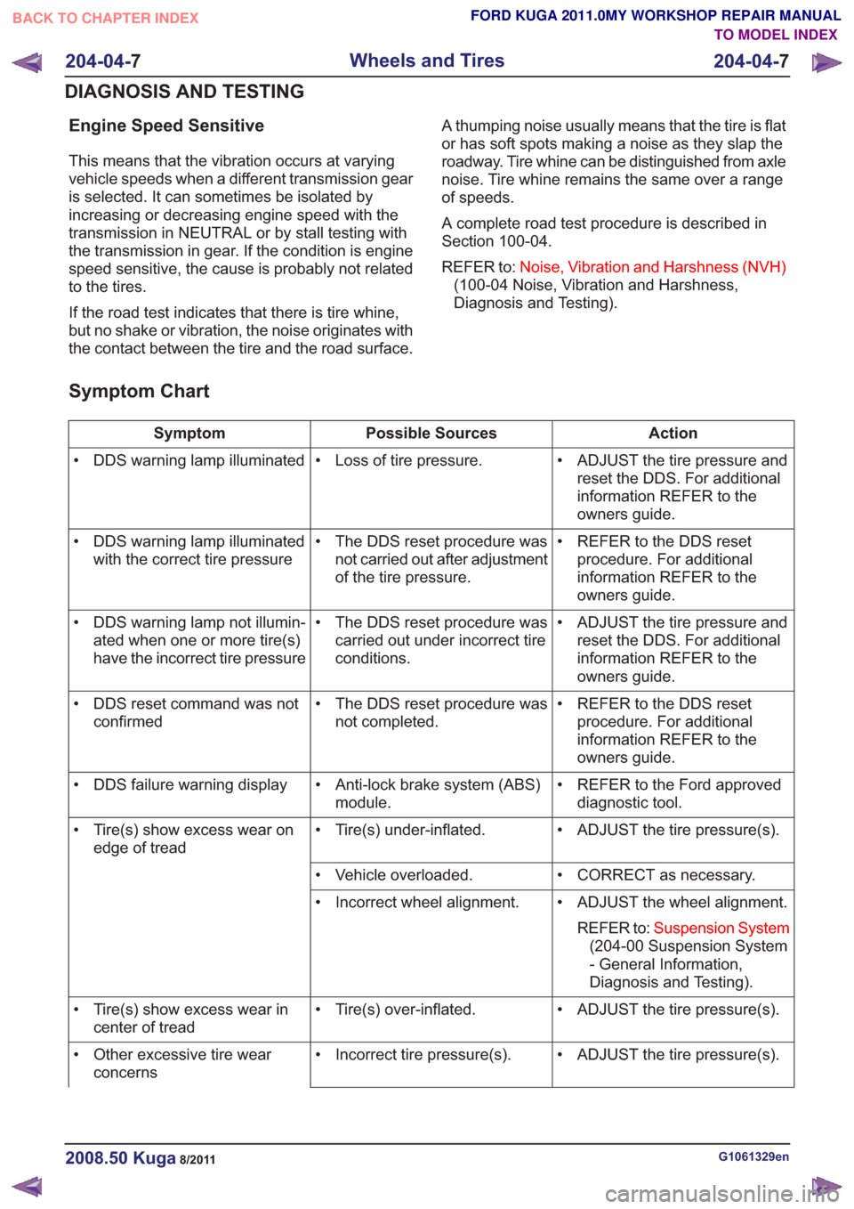
Symptom Chart
Action
Possible Sources
Symptom
• ADJUST the tire pressure andreset the DDS. For additional
information REFER to the
owners guide.
• Loss of tire pressure.
• DDS warning lamp illuminated
• REFER to the DDS resetprocedure. For additional
information REFER to the
owners guide.
• The DDS reset procedure was
not carried out after adjustment
of the tire pressure.
• DDS warning lamp illuminated
with the correct tire pressure
• ADJUST the tire pressure andreset the DDS. For additional
information REFER to the
owners guide.
• The DDS reset procedure was
carried out under incorrect tire
conditions.
• DDS warning lamp not illumin-
ated when one or more tire(s)
have the incorrect tire pressure
• REFER to the DDS resetprocedure. For additional
information REFER to the
owners guide.
• The DDS reset procedure was
not completed.
• DDS reset command was not
confirmed
• REFER to the Ford approveddiagnostic tool.
• Anti-lock brake system (ABS)
module.
• DDS failure warning display
• ADJUST the tire pressure(s).
• Tire(s) under-inflated.
• Tire(s) show excess wear on
edge of tread
• CORRECT as necessary.
• Vehicle overloaded.
• ADJUST the wheel alignment.REFER to: Suspension System
(204-00 Suspension System
- General Information,
Diagnosis and Testing).
• Incorrect wheel alignment.
• ADJUST the tire pressure(s).
• Tire(s) over-inflated.
• Tire(s) show excess wear in
center of tread
• ADJUST the tire pressure(s).
• Incorrect tire pressure(s).
• Other excessive tire wear
concerns
G1061329en2008.50 Kuga8/2011
204-04- 7
Wheels and Tires
204-04- 7
DIAGNOSIS AND TESTING
TO MODEL INDEX
BACK TO CHAPTER INDEX
FORD KUGA 2011.0MY WORKSHOP REPAIR MANUAL
Page 1429 of 2057
HCU to check for sudden actuation of the brakes.
With the brake pedal pressed, the ABS module
triggers emergency braking if the rate of increase
of hydraulic pressure exceeds the predetermined
limit.
If the brake pedal is pressed so hard that the ABS
becomes active on the front wheels then the ABS
control unit increases the pressure to the rear
wheel brakes up to the ABS intervention threshold.
EBA operation continues until the driver releases
the brake pedal sufficiently for the hydraulic
pressure in the HCU to drop below a threshold
value stored in the ABS module.
Trailer stability control:If the vehicle is ordered
with a trailer coupling then the Trailer Stability
Control function is integrated in the ESP. The ESP
detects snaking when driving with a trailer and
reduces the speed of the vehicle and trailer through
adapted braking and, if necessary, by also reducing
the engine output until the snaking movement of
the trailer is corrected.
Roll-over protection: The ESP dynamically
determines the tipping tendency of the vehicle and
works in conjunction with the EBA system to
prevent the vehicle from tipping over during
dynamic maneuvers like lane changing or while
negotiating bends.
Emergency brake light: The emergency brake
light automatically switches on the hazard flasher
system to warn drivers of other vehicles that
emergency braking is being initiated. Based on a
defined delay value, the ABS/ESP module sends
a signal to the generic electronic module (GEM)
via the CAN data bus. The GEM activates the
hazard flasher system, that then flashes 7 times.
Prerequisites for activation of the emergency brake
light are:
• The speed is higher than 50 km/h.
• The brake pedal is being actuated.
• The deceleration is greater than 9 m/s².
To prevent activation on snow or ice, for example,
the following prerequisites must be met:
• The speed is higher than 50 km/h.
• The brake pedal is being actuated.
• ABS regulation takes place.
• The deceleration is greater than 6 m/s².
Tire pressure monitoring system: The tire
pressure monitoring system used in the Kuga is
able to detect loss of air in a tire at an early stage
and warn the driver. Because it can only compare
the behaviour of the tyres with each other, it is not possible to draw conclusions about the absolute
tyre pressure. It is also not possible to monitor the
spare tyre pressure. In order for the system to
operate correctly, the tyre pressures must be
regularly checked and corrected and the system
subsequently initialised (see below).
The tire pressure monitoring system used here,
depending on the equipment level, is built into the
anti-lock braking system (ABS) as an extra function
and therefore does not have its own sensors.
The ABS module measures the loss of pressure
in the tyres by calculation using the wheel speed
sensors of the ABS system. If a tyre loses
pressure, its diameter decreases and the speed of
the wheel therefore increases. If the ABS module
detects such a loss in pressure, it sends a signal
to the instrument cluster via the CAN bus and a
warning message is displayed in the message
centre. The warning threshold depends among
other things on the dimension of the tyres being
used, the vehicle operating conditions and the
status at the last initialisation. Since neither the
absolute tyre pressure nor the position of the tyre
is known, the pressure of all the tyres must be
checked and the system re-initialised after a tyre
pressure warning. If necessary, the cause of the
loss of pressure must be investigated.
Regular tyre pressure checks are still necessary.
The system must be initialised after a tyre is
changed, winter or summer tyres fitted, the
pressures corrected or adjusted to suit the vehicle
load. This can be done by the driver using the
driver information system. For further information,
see: Owner’s Manual.
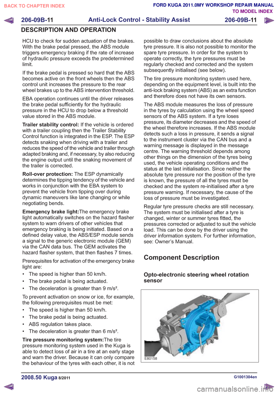
Component Description
Opto-electronic steering wheel rotation
sensor
E80158
G1001304en2008.50 Kuga8/2011
206-09B-
11
Anti-Lock Control - Stability Assist
206-09B- 11
DESCRIPTION AND OPERATION
TO MODEL INDEX
BACK TO CHAPTER INDEX
FORD KUGA 2011.0MY WORKSHOP REPAIR MANUAL