Page 1411 of 2057
Brake Vacuum Hose — 2.5L Duratec (147kW/200PS) - VI5
Removal
NOTE:Removal steps in this procedure may
contain installation details.Left-hand drive vehicles
1.
E113948
Right-hand drive vehicles
2.
G1174983en2008.50 Kuga8/2011
206-07- 7
Power Brake Actuation
206-07- 7
REMOVAL AND INSTALLATION
TO MODEL INDEX
BACK TO CHAPTER INDEX
FORD KUGA 2011.0MY WORKSHOP REPAIR MANUAL
Page 1413 of 2057
Brake Vacuum Pump — 2.5L Duratec (147kW/200PS) -VI5(12 414 0)
Removal
NOTE: Removal steps in this procedure may
contain installation details.
1. Torque: 10
Nm
E74256
x2
Installation
1.To install, reverse the removal procedure.
G543409en2008.50 Kuga8/2011
206-07- 9
Power Brake Actuation
206-07- 9
REMOVAL AND INSTALLATION
TO MODEL INDEX
BACK TO CHAPTER INDEX
FORD KUGA 2011.0MY WORKSHOP REPAIR MANUAL
Page 1458 of 2057

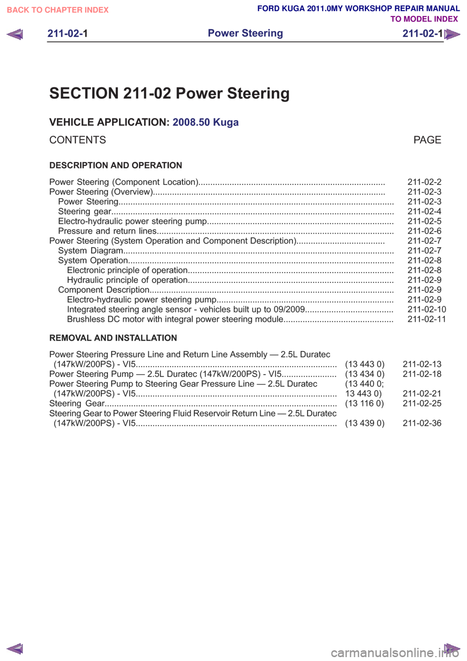
SECTION 211-02 Power Steering
VEHICLE APPLICATION:2008.50 Kuga
PA G E
CONTENTS
DESCRIPTION AND OPERATION
211-02-2
Power Steering (Component Location) ........................................................................\
......
211-02-3
Power Steering (Overview) ........................................................................\
.........................
211-02-3
Power Steering ........................................................................\
...........................................
211-02-4
Steering gear ........................................................................\
..............................................
211-02-5
Electro-hydraulic power steering pump ........................................................................\
......
211-02-6
Pressure and return lines ........................................................................\
...........................
211-02-7
Power Steering (System Operation and Component Description) .....................................
211-02-7
System Diagram ........................................................................\
.........................................
211-02-8
System Operation ........................................................................\
.......................................
211-02-8
Electronic principle of operation ........................................................................\
..............
211-02-9
Hydraulic principle of operation ........................................................................\
..............
211-02-9
Component Description ........................................................................\
..............................
211-02-9
Electro-hydraulic power steering pump ........................................................................\
..
211-02-10
Integrated steering angle sensor - vehicles built up to 09/2009 .....................................
211-02-11
Brushless DC motor with integral power steering module..............................................
REMOVAL AND INSTALLATION
211-02-13
(13 443 0)
Power Steering Pressure Line and Return Line Assembly — 2.5L Duratec
(147kW/200PS) - VI5 ........................................................................\
............
211-02-18
(13 434 0)
Power Steering Pump — 2.5L Duratec (147kW/200PS) - VI5 .......................
211-02-21
(13 440 0;
13 443 0)
Power Steering Pump to Steering Gear Pressure Line — 2.5L Duratec
(147kW/200PS) - VI5 ........................................................................\
............
211-02-25
(13 116 0)
Steering Gear ........................................................................\
.........................
211-02-36
(13 439 0)
Steering Gear to Power Steering Fluid Reservoir Return Line — 2.5L Duratec
(147kW/200PS) - VI5 ........................................................................\
............
211-02-1
Power Steering
211-02- 1
.
TO MODEL INDEX
BACK TO CHAPTER INDEX
FORD KUGA 2011.0MY WORKSHOP REPAIR MANUAL
Page 1470 of 2057
Power Steering Pressure Line and Return Line Assembly — 2.5LDuratec (147kW/200PS) - VI5(13 443 0)
General Equipment
Hose Clamp Remover/Installer
Removal
NOTE: Removal steps in this procedure may
contain installation details.
1. Refer to: Steering System Health and Safety
Precautions (100-00 General Information,
Description and Operation).
2. Refer to: Wheel and Tire (204-04 Wheels and
Tires, Removal and Installation).
3.
E98543
x7
4.
E99630
5.
E99631
6. WARNING: Be prepared to collect escaping fluid.
1. General Equipment: Hose ClampRemover/Installer
2. Torque: 30
Nm
E114706
1
2
7. Torque: 23Nm1.
2. Torque: 7
Nm
G1185534en2008.50 Kuga8/2011
211-02- 13
Power Steering
211-02- 13
REMOVAL AND INSTALLATION
TO MODEL INDEX
BACK TO CHAPTER INDEX
FORD KUGA 2011.0MY WORKSHOP REPAIR MANUAL
Page 1475 of 2057
Power Steering Pump — 2.5L Duratec (147kW/200PS) -VI5(13 434 0)
General Equipment
Hose Clamp(s)
Hose Clamp Remover/Installer
Removal
NOTE: Removal steps in this procedure may
contain installation details.
1. Refer to: Steering System Health and Safety
Precautions (100-00 General Information,
Description and Operation).
2. Refer to: Wheel and Tire (204-04 Wheels and
Tires, Removal and Installation).
3.
E98543
x7
4.
E99630
5.
E99631
6. 1. WARNING: Be prepared to collect
escaping fluid.
General Equipment: Hose Clamp(s)
2. General Equipment: Hose Clamp Remover/Installer
E114163
12
7.1. WARNING: Be prepared to collect
escaping fluid.
Torque: 30Nm
3. General Equipment: Hose Clamp
Remover/Installer
4. Torque: 10
Nm
G1176952en2008.50 Kuga8/2011
211-02- 18
Power Steering
211-02- 18
REMOVAL AND INSTALLATION
TO MODEL INDEX
BACK TO CHAPTER INDEX
FORD KUGA 2011.0MY WORKSHOP REPAIR MANUAL
Page 1478 of 2057
Power Steering Pump to Steering Gear Pressure Line — 2.5LDuratec (147kW/200PS) - VI5(13 440 0; 13 443 0)
General Equipment
Hose Clamp Remover/Installer
Removal
NOTE: Removal steps in this procedure may
contain installation details.
1. Refer to: Steering System Health and Safety
Precautions (100-00 General Information,
Description and Operation).
2. Refer to: Wheel and Tire (204-04 Wheels and
Tires, Removal and Installation).
3.
E98543
x7
4.
E99630
5.
E99631
6. WARNING: Be prepared to collect escaping fluid.
1. General Equipment: Hose ClampRemover/Installer
2. Torque: 30
Nm
E114706
1
2
7. Torque: 23Nm1.
2. Torque: 7
Nm
G1185535en2008.50 Kuga8/2011
211-02- 21
Power Steering
211-02- 21
REMOVAL AND INSTALLATION
TO MODEL INDEX
BACK TO CHAPTER INDEX
FORD KUGA 2011.0MY WORKSHOP REPAIR MANUAL
Page 1491 of 2057
Vehicles with 2.5L engine
11 .
E141077
12.
E141078
13. N O T E :Make sure the fluid in the reservoir does
not fall below the MIN mark, as air could enter
the system.
Slowly turn the steering wheel from lock to lock
five times.
E131522
123
14.
E141079
12
15.
E141077
G1001271en2008.50 Kuga8/2011
211-02- 34
Power Steering
211-02- 34
REMOVAL AND INSTALLATION
TO MODEL INDEX
BACK TO CHAPTER INDEX
FORD KUGA 2011.0MY WORKSHOP REPAIR MANUAL
Page 1493 of 2057
Steering Gear to Power Steering Fluid Reservoir Return Line —2.5L Duratec (147kW/200PS) - VI5(13 439 0)
General Equipment
Hose Clamp Remover/Installer
Removal
NOTE: Removal steps in this procedure may
contain installation details.
1. Refer to: Steering System Health and Safety
Precautions (100-00 General Information,
Description and Operation).
2. Refer to: Wheel and Tire (204-04 Wheels and
Tires, Removal and Installation).
3.
E98543
x7
4.
E99630
5.
E99631
6. WARNING: Be prepared to collect escaping fluid.
1. General Equipment: Hose ClampRemover/Installer
2. Torque: 30
Nm
E114706
1
2
7. Torque: 23Nm1.
2. Torque: 7
Nm
G1185536en2008.50 Kuga8/2011
211-02- 36
Power Steering
211-02- 36
REMOVAL AND INSTALLATION
TO MODEL INDEX
BACK TO CHAPTER INDEX
FORD KUGA 2011.0MY WORKSHOP REPAIR MANUAL