2011 FORD KUGA tow
[x] Cancel search: towPage 1823 of 2057

307-01-29
Automatic transmission, selector lever in position "D". ...................................................
307-01-29
Sport mode, selector lever in position "S" .......................................................................
307-01-29
Changing gear in select-shift mode........................................................................\
........
307-01-30
Selector lever from 'N' to 'R' position ........................................................................\
......
307-01-30
Self-test and Diagnosis ........................................................................\
...........................
307-01-30
Temperature controlled torque converter lockup ............................................................
307-01-30
Slip locking ........................................................................\
..............................................
307-01-30
Hill climbing ........................................................................\
.............................................
307-01-31
Downhill driving ........................................................................\
.......................................
307-01-31
Hill-hold function ........................................................................\
.....................................
307-01-31
Altitude correction ........................................................................\
...................................
307-01-31
Selector lever lock ........................................................................\
..................................
307-01-31
Shifting from P into another transmission range .............................................................
307-01-31
Shifting from N into another transmission range .............................................................
307-01-31
Power flow through the transmission ........................................................................\
......
307-01-31
Clutches and brakes ........................................................................\
...............................
307-01-33
Position P (park) ........................................................................\
.....................................
307-01-34
Position N (neutral) ........................................................................\
.................................
307-01-35
Position D, 1st gear........................................................................\
................................
307-01-36
Position D, 2nd gear ........................................................................\
...............................
307-01-37
Position D, 3rd gear ........................................................................\
................................
307-01-38
Position D, 4th gear ........................................................................\
................................
307-01-39
Position D, 5th gear ........................................................................\
................................
307-01-40
Position R (reverse) ........................................................................\
................................
307-01-41
Service instructions ........................................................................\
.................................
307-01-41
Towing procedure ........................................................................\
...................................
307-01-42
Reset adaptation data ........................................................................\
.............................
307-01-42
Limp home mode ........................................................................\
....................................
307-01-42
Component Description ........................................................................\
..............................
Tasks of the electronic components ........................................................................\
........
307-01-44
Input signals ........................................................................\
............................................
307-01-45
Output signals ........................................................................\
.........................................
Control valve assembly ........................................................................\
...........................
Shift solenoids S1 - S5 ........................................................................\
...........................
PWM-
solenoid valve – TCC (SLU) ........................................................................\
........
PWM solenoid valve – shift pressure (SLS) ...................................................................
PWM solenoid valve for main line pressure (SLT) ..........................................................
307-01-52
Installation position ........................................................................\
.................................
Operation ........................................................................\
................................................
Selector lever with integrated select-shift switch module ...............................................
Oil pump ........................................................................\
..................................................
Torque converter with TCC ........................................................................\
.....................
The TSS sensor ........................................................................\
......................................
The OSS sensor ........................................................................\
.....................................
The TFT sensor ........................................................................\
......................................
The TR sensor ........................................................................\
........................................
GENERAL PROCEDURES
T ransmission Fluid Level Check ........................................................................\
.................
307-01-63
T ransmission Fluid Drain and Refill ........................................................................\
............
REMOVAL AND INSTALLATION 307-01-67
Halfshaft Seal LH ........................................................................\
........................................
307-01-68
Halfshaft Seal RH........................................................................\
.......................................
307-01-69
Main Control Valve Body ........................................................................\
............................
307-01-2
Automatic Transmission/Transaxle
— Vehicles With:
5-Speed Automatic Transaxle - AW55 AWD
307-01- 2
.
TO MODEL INDEX
BACK TO CHAPTER INDEX
307-01-42
307-01-49
307-01-52 307-01-47
307-01-45
307-01-50
307-01-51
307-01-53
307-01-55
307-01-54
307-01-56
307-01-57
307-01-58
307-01-61 307-01-60
PAGE 2 OF 3 FORD KUGA 2011.0MY WORKSHOP REPAIR MANUAL
Page 1836 of 2057

• Selector lever position and selector leverposition display
• Fluid leakage
• Transmission fluid level check
• Transmission fluid quality check
• Modification/retrofitting
• Mechanical damage to the transmission
When inspecting connectors, remember that the
plugs may only be disconnected when they are not
energized.
The transaxle electronics may be destroyed by
static charge. To prevent damage, it must be
ensured that the technician complies with the
corresponding safeguards.
NOTE: Refer to the service literature for an exact
description of these safeguards.
Towing the vehicle
E66463
In general, vehicles with the AW55 transaxle can
be towed. Vehicles must never be towed
backwards.
As a result of the reduced lubrication of the
transaxle during towing, the following must be
remembered:
• The selector lever must be in the 'N' position.
• The maximum towing speed must not exceed 50 km/h.
• The maximum towing distance must not exceed 50 kilometers.
Push-starting the Vehicle
No torque is transmitted when towing or pushing
the vehicle. For this reason, vehicles with an
automatic transaxle cannot and must not be
tow-started or push-started.
Jump-starting the Vehicle
CAUTION: When jump-starting the vehicle
using a jumper lead there may be voltage
peaks. These may destroy the transaxle
electronics.
NOTE: When jump-starting the vehicle, the external
battery must remain connected for several minutes.
The voltage peaks dissipate after a few minutes.
Only then may the external battery be disconnected
without the risk of damage.
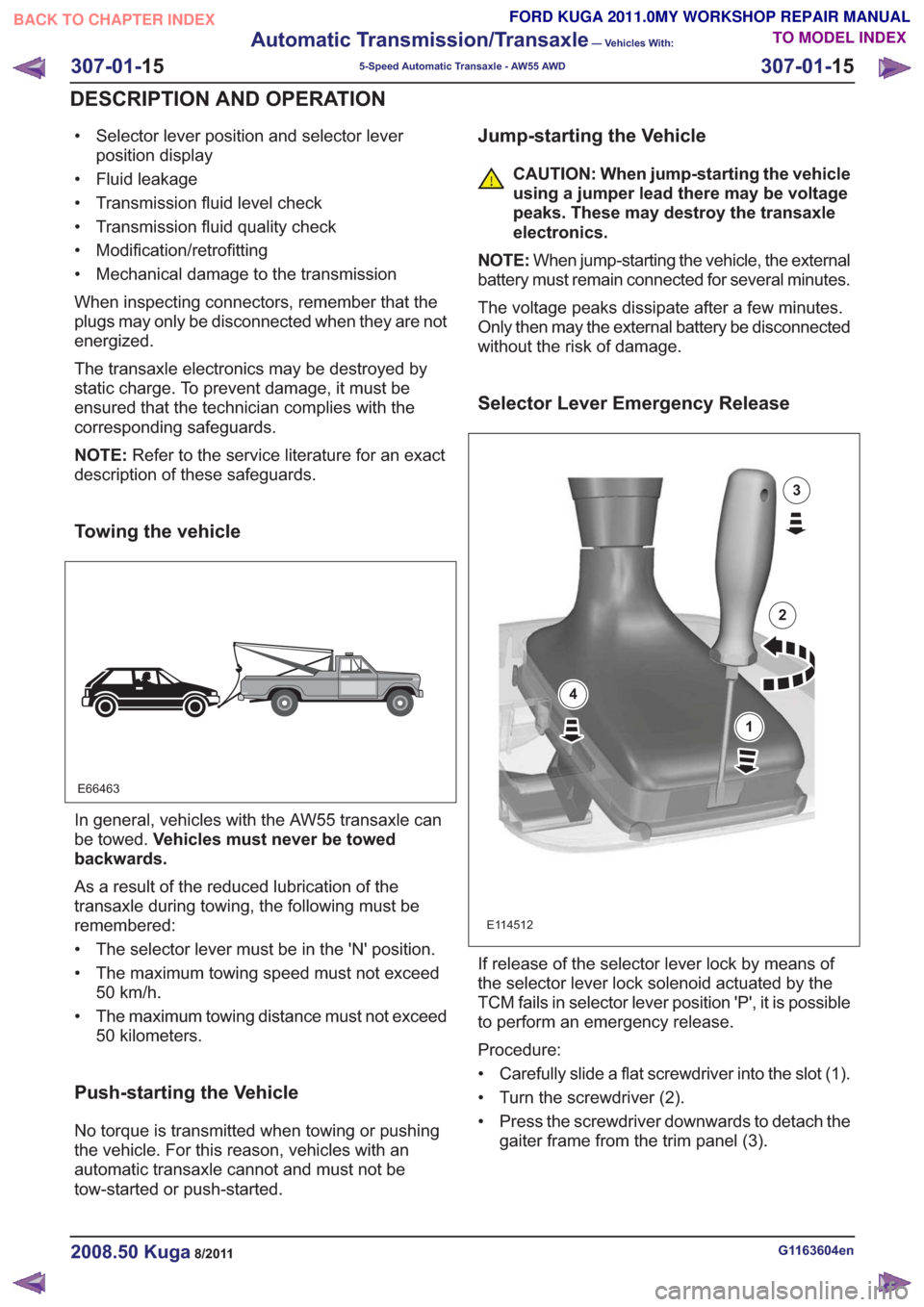
Selector Lever Emergency Release
E114512
1
2
3
4
If release of the selector lever lock by means of
the selector lever lock solenoid actuated by the
TCM fails in selector lever position 'P', it is possible
to perform an emergency release.
Procedure:
• Carefully slide a flat screwdriver into the slot (1).
• Turn the screwdriver (2).
• Press the screwdriver downwards to detach the gaiter frame from the trim panel (3).
G1163604en2008.50 Kuga8/2011
307-01- 15
Automatic Transmission/Transaxle
— Vehicles With:
5-Speed Automatic Transaxle - AW55 AWD
307-01- 15
DESCRIPTION AND OPERATION
TO MODEL INDEX
BACK TO CHAPTER INDEX
FORD KUGA 2011.0MY WORKSHOP REPAIR MANUAL
Page 1862 of 2057

E127362
12
3
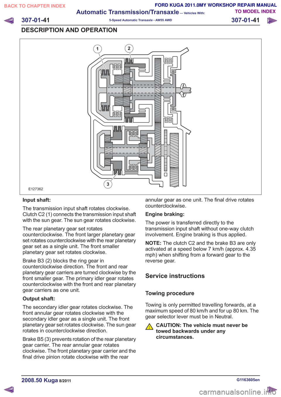
Input shaft:
The transmission input shaft rotates clockwise.
Clutch C2 (1) connects the transmission input shaft
with the sun gear. The sun gear rotates clockwise.
The rear planetary gear set rotates
counterclockwise. The front larger planetary gear
set rotates counterclockwise with the rear planetary
gear set as a single unit. The front smaller
planetary gear set rotates clockwise.
Brake B3 (2) blocks the ring gear in
counterclockwise direction. The front and rear
planetary gear carriers are turned clockwise by the
front smaller gear. The primary idler gear rotates
counterclockwise with the front and rear planetary
gear carriers as one unit.
Output shaft:
The secondary idler gear rotates clockwise. The
front annular gear rotates clockwise with the
secondary idler gear as a single unit. The front
planetary gear set rotates clockwise. The sun gear
rotates in counterclockwise direction.
Brake B5 (3) prevents rotation of the rear planetary
gear carrier. The rear annular gear rotates
clockwise. The front planetary gear carrier and the
final drive pinion rotate clockwise with the rearannular gear as one unit. The final drive rotates
counterclockwise.
Engine braking:
The power is transferred directly to the
transmission input shaft without one-way clutch
involvement. Engine braking is thus applied.
NOTE:
The clutch C2 and the brake B3 are only
activated at a speed below 7 km/h (approx. 4.35
mph) when shifting from a forward gear to the
reverse gear.
Service instructions
Towing procedure
Towing is only permitted travelling forwards, at a
maximum speed of 80 km/h and for up 80 km. The
gear selector lever must be in Neutral.
CAUTION: The vehicle must never be
towed backwards under any
circumstances.
G1163605en2008.50 Kuga8/2011
307-01- 41
Automatic Transmission/Transaxle
— Vehicles With:
5-Speed Automatic Transaxle - AW55 AWD
307-01- 41
DESCRIPTION AND OPERATION
TO MODEL INDEX
BACK TO CHAPTER INDEX
FORD KUGA 2011.0MY WORKSHOP REPAIR MANUAL