2011 FORD KUGA ECT
[x] Cancel search: ECTPage 1192 of 2057
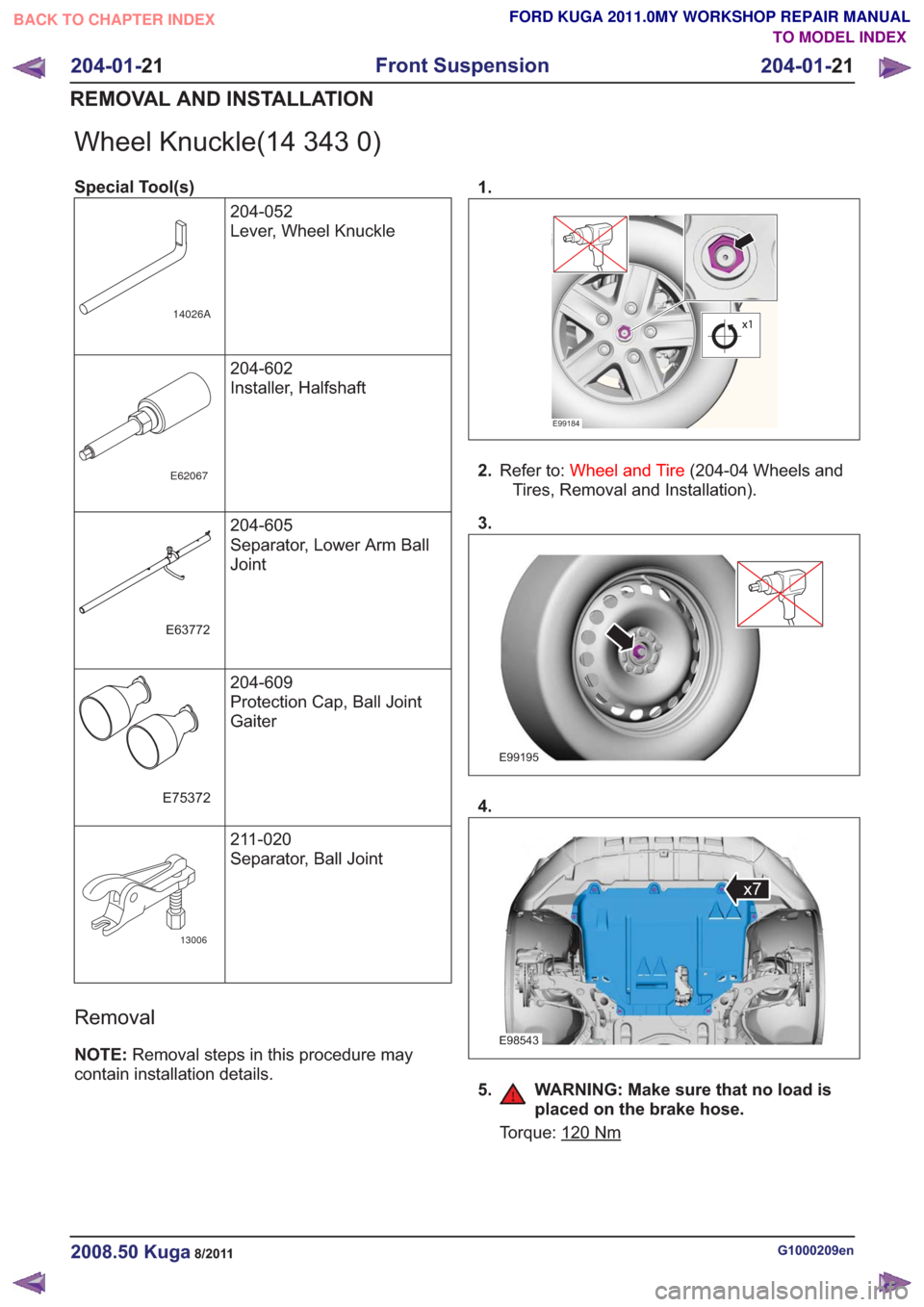
Wheel Knuckle(14 343 0)
Special Tool(s)204-052
Lever, Wheel Knuckle
14026A
204-602
Installer, Halfshaft
E62067
204-605
Separator, Lower Arm Ball
Joint
E63772
204-609
Protection Cap, Ball Joint
Gaiter
E75372
211-020
Separator, Ball Joint
13006
Removal
NOTE:Removal steps in this procedure may
contain installation details. 1.
E99184
2.
Refer to: Wheel and Tire (204-04 Wheels and
Tires, Removal and Installation).
3.
E99195
4.
E98543
x7
5. WARNING: Make sure that no load is placed on the brake hose.
Torque: 120Nm
G1000209en2008.50 Kuga8/2011
204-01- 21
Front Suspension
204-01- 21
REMOVAL AND INSTALLATION
TO MODEL INDEX
BACK TO CHAPTER INDEX
FORD KUGA 2011.0MY WORKSHOP REPAIR MANUAL
Page 1201 of 2057
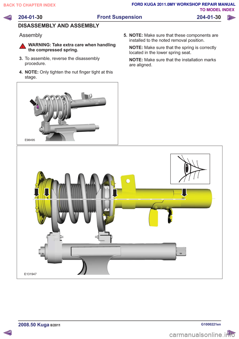
Assembly
WARNING: Take extra care when handling
the compressed spring.
3. To assemble, reverse the disassembly
procedure.
4. NOTE: Only tighten the nut finger tight at this
stage.
E98495
5. NOTE: Make sure that these components are
installed to the noted removal position.
NOTE: Make sure that the spring is correctly
located in the lower spring seat.
NOTE: Make sure that the installation marks
are aligned.
E131947
G1000221en2008.50 Kuga8/2011
204-01- 30
Front Suspension
204-01- 30
DISASSEMBLY AND ASSEMBLY
TO MODEL INDEX
BACK TO CHAPTER INDEX
FORD KUGA 2011.0MY WORKSHOP REPAIR MANUAL
Page 1203 of 2057
SECTION 204-02 Rear Suspension
VEHICLE APPLICATION:2008.50 Kuga
PA G E
CONTENTS
SPECIFICATIONS
204-02-2
Specifications ........................................................................\
..............................................
DESCRIPTION AND OPERATION 204-02-3
Rear Suspension (Overview) ........................................................................\
......................
204-02-3
Overview ........................................................................\
.....................................................
204-02-4
Upper control arm ........................................................................\
.......................................
204-02-4
Rear lower arm and spring lower pad ........................................................................\
.........
204-02-4
Front lower arm ........................................................................\
..........................................
204-02-5
Stabilizer bar ........................................................................\
...............................................
REMOVAL AND INSTALLATION 204-02-6
Wheel Bearing and Wheel Hub ........................................................................\
..................
204-02-9
(15 701 0)
Upper Arm ........................................................................\
..............................
204-02-11
(15 690 0)
Front Lower Arm ........................................................................\
.....................
204-02-13
(15 705 0)
Rear Lower Arm ........................................................................\
.....................
204-02-15
(15 752 0)
Rear Stabilizer Bar ........................................................................\
.................
204-02-17
Rear Stabilizer Bar Link ........................................................................\
..............................
204-02-18
Rear Stabilizer Bar Bushing ........................................................................\
.......................
204-02-19
Wheel Knuckle — LHD FWD/RHD FWD ........................................................................\
....
204-02-22
Wheel Knuckle — LHD 4WD/RHD 4WD ........................................................................\
....
204-02-25
(15 621 0)
Spring ........................................................................\
.....................................
204-02- 1
Rear Suspension
204-02- 1
.
TO MODEL INDEX
BACK TO CHAPTER INDEX
FORD KUGA 2011.0MY WORKSHOP REPAIR MANUAL
Page 1206 of 2057
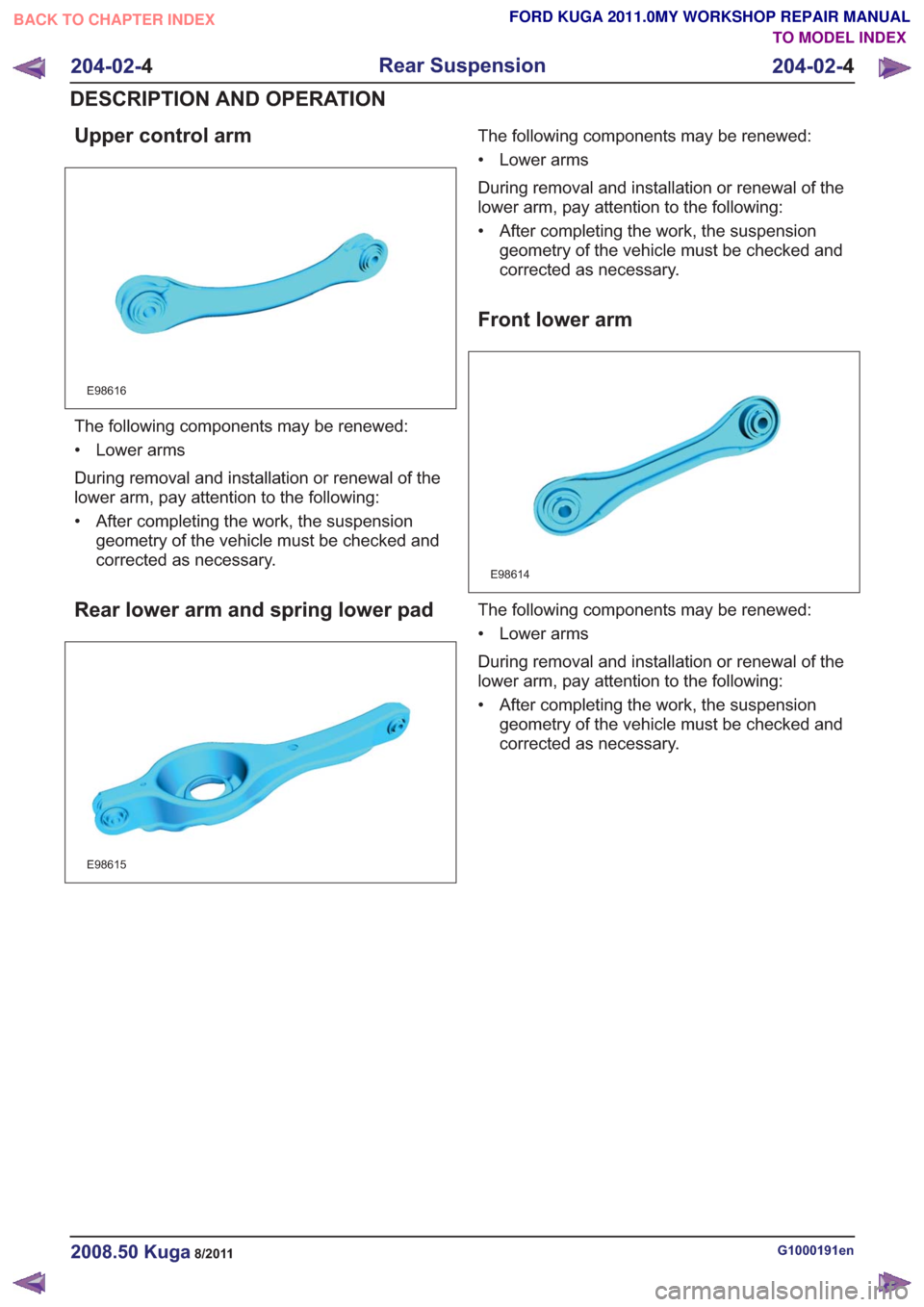
Upper control arm
E98616
The following components may be renewed:
• Lower arms
During removal and installation or renewal of the
lower arm, pay attention to the following:
• After completing the work, the suspensiongeometry of the vehicle must be checked and
corrected as necessary.
Rear lower arm and spring lower pad
E98615
The following components may be renewed:
• Lower arms
During removal and installation or renewal of the
lower arm, pay attention to the following:
• After completing the work, the suspensiongeometry of the vehicle must be checked and
corrected as necessary.
Front lower arm
E98614
The following components may be renewed:
• Lower arms
During removal and installation or renewal of the
lower arm, pay attention to the following:
• After completing the work, the suspensiongeometry of the vehicle must be checked and
corrected as necessary.
G1000191en2008.50 Kuga8/2011
204-02- 4
Rear Suspension
204-02- 4
DESCRIPTION AND OPERATION
TO MODEL INDEX
BACK TO CHAPTER INDEX
FORD KUGA 2011.0MY WORKSHOP REPAIR MANUAL
Page 1228 of 2057
SECTION 204-04 Wheels and Tires
VEHICLE APPLICATION:2008.50 Kuga
PA G E
CONTENTS
SPECIFICATIONS
204-04-2
Specifications ........................................................................\
..............................................
DESCRIPTION AND OPERATION 204-04-3
Wheels and Tires (Overview) ........................................................................\
.....................
204-04-3
Tire/wheel rim combinations ........................................................................\
.......................
204-04-3
Use of snow chains ........................................................................\
....................................
204-04-3
Tire repair kit ........................................................................\
...............................................
204-04-4
Run-Flat Tires (Overview) ........................................................................\
...........................
204-04-4
Tires with Run-flat Properties ........................................................................\
.....................
204-04-5
Tire Pressure Monitoring System (TPMS) (Overview) ........................................................
204-04-5
Description of operation ........................................................................\
..............................
DIAGNOSIS AND TESTING 204-04-6
Wheels and Tires ........................................................................\
........................................
204-04-6
Inspection and Verification ........................................................................\
..........................
204-04-7
Symptom Chart ........................................................................\
...........................................
REMOVAL AND INSTALLATION 204-04-11
Wheel and Tire........................................................................\
...........................................
204-04- 1
Wheels and Tires
204-04- 1
.
TO MODEL INDEX
BACK TO CHAPTER INDEX
FORD KUGA 2011.0MY WORKSHOP REPAIR MANUAL
Page 1231 of 2057
Run-Flat Tires – Overview
Tires with Run-flat Properties
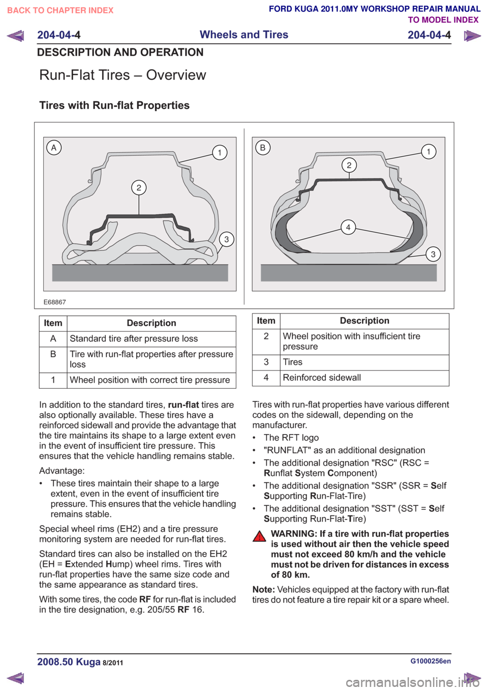
E68867
2
1
3
2
4
1
3
BA
Description
Item
Standard tire after pressure loss
A
Tire with run-flat properties after pressure
loss
B
Wheel position with correct tire pressure
1Description
Item
Wheel position with insufficient tire
pressure
2
Tires
3
Reinforced sidewall
4
In addition to the standard tires, run-flattires are
also optionally available. These tires have a
reinforced sidewall and provide the advantage that
the tire maintains its shape to a large extent even
in the event of insufficient tire pressure. This
ensures that the vehicle handling remains stable.
Advantage:
• These tires maintain their shape to a large extent, even in the event of insufficient tire
pressure. This ensures that the vehicle handling
remains stable.
Special wheel rims (EH2) and a tire pressure
monitoring system are needed for run-flat tires.
Standard tires can also be installed on the EH2
(EH = Extended Hump) wheel rims. Tires with
run-flat properties have the same size code and
the same appearance as standard tires.
With some tires, the code RFfor run-flat is included
in the tire designation, e.g. 205/55 RF16. Tires with run-flat properties have various different
codes on the sidewall, depending on the
manufacturer.
• The RFT logo
• "RUNFLAT" as an additional designation
• The additional designation "RSC" (RSC =
Runflat System Component)
• The additional designation "SSR" (SSR = Self
S upporting Run-Flat-Tire)
• The additional designation "SST" (SST = Self
S upporting Run-Flat- Tire)
WARNING: If a tire with run-flat properties
is used without air then the vehicle speed
must not exceed 80 km/h and the vehicle
must not be driven for distances in excess
of 80 km.
Note: Vehicles equipped at the factory with run-flat
tires do not feature a tire repair kit or a spare wheel.
G1000256en2008.50 Kuga8/2011
204-04- 4
Wheels and Tires
204-04- 4
DESCRIPTION AND OPERATION
TO MODEL INDEX
BACK TO CHAPTER INDEX
FORD KUGA 2011.0MY WORKSHOP REPAIR MANUAL
Page 1232 of 2057
Tire Pressure Monitoring System (TPMS) – Overview
Description of operation
The tire pressure monitoring system is able to
detect loss of air in a tire at an early stage and warn
the driver. Because it can only compare the
behavior of the tires with each other, it is not
possible to draw conclusions about the absolute
tire pressure. It is also not possible to monitor the
spare tire pressure. In order for the system to
operate correctly, the tire pressures must be
regularly checked and corrected and the system
subsequently initialized (see below).
The tire pressure monitoring system used here,
depending on the equipment level, is built into the
anti-lock braking system (ABS) as an extra function
and therefore does not have its own sensors.
The ABS module determines the loss of pressure
in the tires by calculation using the wheel speed
sensors of the ABS system. If a tire loses pressure,
its diameter decreases and the speed of the wheel
therefore increases. If the ABS module detects
such a loss in pressure, it sends a signal to the
instrument cluster via the CAN bus and a warning
message is displayed in the driver information
system. The warning threshold depends among
other things on the dimension of the tires being
used, the vehicle operating conditions and the
status at the last initialization. Since neither the
absolute tire pressure nor the position of the tire is
known, after a tire pressure warning the pressure
of all the tires must be checked and the system
re-initialized. If necessary, the cause of the loss of
pressure must be investigated.
Furthermore, regular pressure checks are
necessary. The system must be initialized after a
tire is changed, winter or summer tires fitted, the
pressures corrected or adjusted to suit the vehicle
load. This can be done by the driver using the
driver information system. For further information,
see: Owner’s Manual.
G1001290en2008.50 Kuga8/2011
204-04-5
Wheels and Tires
204-04- 5
DESCRIPTION AND OPERATION
TO MODEL INDEX
BACK TO CHAPTER INDEX
FORD KUGA 2011.0MY WORKSHOP REPAIR MANUAL
Page 1233 of 2057
Wheels and Tires
Inspection and Verification
Visual Inspection Chart
MechanicalWheel(s)Tire(s)
Tire pressure(s) * Wheel nuts
Wheel studs
* Vehicles equipped with a tire deflation detection system (DDS) must be inspected for correct operation using the Ford approved diagnostic tool.
To maximize tire performance, inspect the tires for
signs of incorrect inflation and uneven wear which
may indicate a need for balancing, rotation or
suspension alignment. Tires should also be
checked frequently for cuts, stone bruises,
abrasions, blisters and for objects that may have
become embedded in the tread. More frequent
inspections are recommended when rapid or
extreme temperature changes occur or when road
surfaces are rough or occasionally littered with
foreign material.
As a further visible check of tire condition, tread
wear indicators are molded into the bottom of the
tread grooves. When these indicator bands become
visible, new tires must be installed.
Tire Wear Diagnosis
Uneven wear is usually caused by either excessive
camber or excessive toe on tires.
Sometimes incorrect toe settings or worn struts will
cause severe `cupping' or `scalloped' tire wear on
non-driven wheels.
Severely incorrect toe settings will also cause other
unusual wear patterns.
Tire Vibration Diagnosis
A tire vibration diagnostic procedure always begins
with a road test. The road test and customer
interview (if available) will provide much of the
information needed to find the source of a vibration. During the road test, drive the vehicle on a road
that is smooth and free of undulations. If vibration
is apparent, note and record the following:
– the speed at which the vibration occurs.
– what type of vibration occurs in each speed
range.
– mechanical or audible
– how the vibration is affected by changes in the following:
– engine torque
– vehicle speed
– engine speed
– type of vibration - sensitivity: – torque sensitive
– vehicle speed sensitive
– engine speed sensitive
The following explanations help isolate the source
of the vibration.
Torque Sensitive
This means that the condition can be improved or
made worse by accelerating, decelerating,
coasting, maintaining a steady vehicle speed or
applying engine torque.
Vehicle Speed Sensitive
This means that the vibration always occurs at the
same vehicle speed and is not affected by engine
torque, engine speed or the transmission gear
selected.
G1061329en2008.50 Kuga8/2011
204-04- 6
Wheels and Tires
204-04- 6
DIAGNOSIS AND TESTING
TO MODEL INDEX
BACK TO CHAPTER INDEX
FORD KUGA 2011.0MY WORKSHOP REPAIR MANUAL