2011 FORD KUGA ECT
[x] Cancel search: ECTPage 1234 of 2057
Engine Speed Sensitive
This means that the vibration occurs at varying
vehicle speeds when a different transmission gear
is selected. It can sometimes be isolated by
increasing or decreasing engine speed with the
transmission in NEUTRAL or by stall testing with
the transmission in gear. If the condition is engine
speed sensitive, the cause is probably not related
to the tires.
If the road test indicates that there is tire whine,
but no shake or vibration, the noise originates with
the contact between the tire and the road surface.A thumping noise usually means that the tire is flat
or has soft spots making a noise as they slap the
roadway. Tire whine can be distinguished from axle
noise. Tire whine remains the same over a range
of speeds.
A complete road test procedure is described in
Section 100-04.
REFER to:
Noise, Vibration and Harshness (NVH)
(100-04 Noise, Vibration and Harshness,
Diagnosis and Testing).
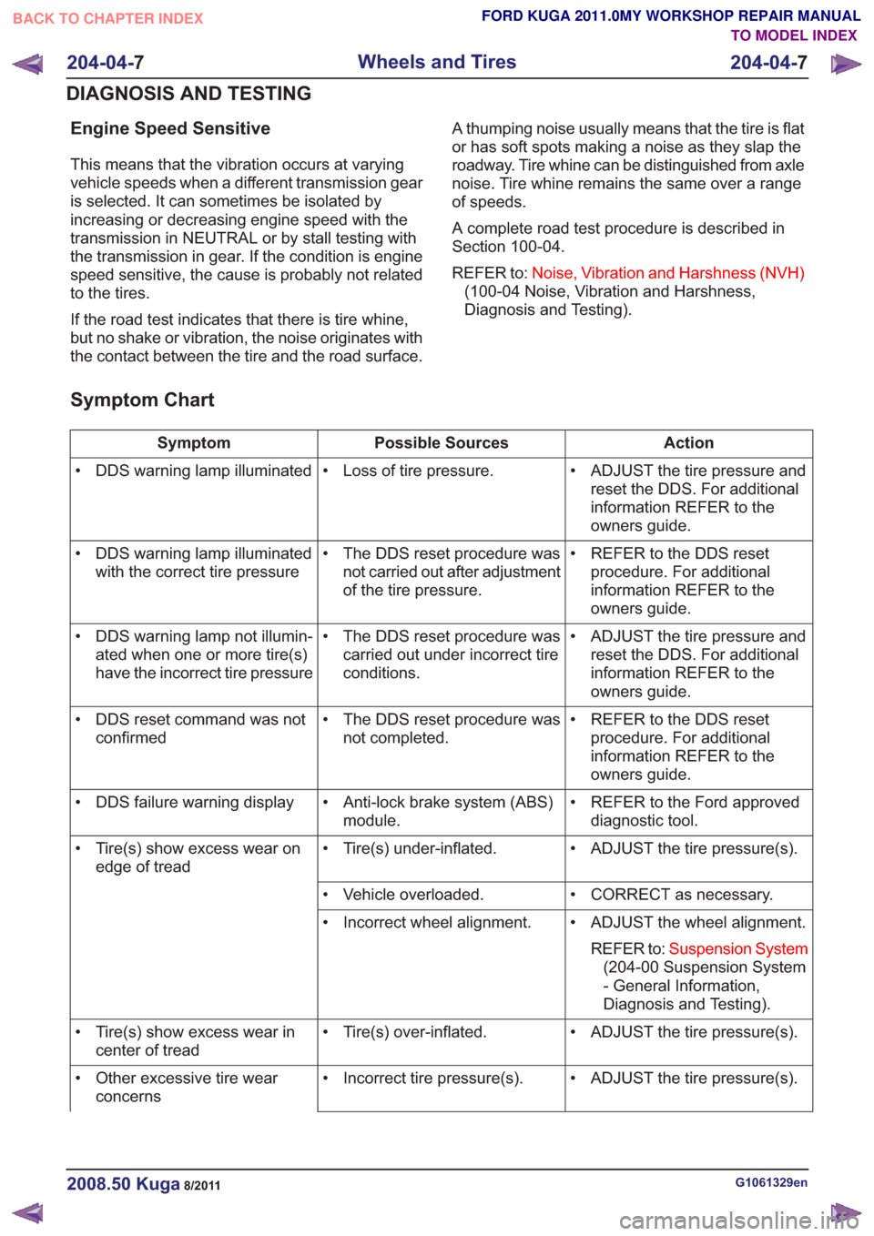
Symptom Chart
Action
Possible Sources
Symptom
• ADJUST the tire pressure andreset the DDS. For additional
information REFER to the
owners guide.
• Loss of tire pressure.
• DDS warning lamp illuminated
• REFER to the DDS resetprocedure. For additional
information REFER to the
owners guide.
• The DDS reset procedure was
not carried out after adjustment
of the tire pressure.
• DDS warning lamp illuminated
with the correct tire pressure
• ADJUST the tire pressure andreset the DDS. For additional
information REFER to the
owners guide.
• The DDS reset procedure was
carried out under incorrect tire
conditions.
• DDS warning lamp not illumin-
ated when one or more tire(s)
have the incorrect tire pressure
• REFER to the DDS resetprocedure. For additional
information REFER to the
owners guide.
• The DDS reset procedure was
not completed.
• DDS reset command was not
confirmed
• REFER to the Ford approveddiagnostic tool.
• Anti-lock brake system (ABS)
module.
• DDS failure warning display
• ADJUST the tire pressure(s).
• Tire(s) under-inflated.
• Tire(s) show excess wear on
edge of tread
• CORRECT as necessary.
• Vehicle overloaded.
• ADJUST the wheel alignment.REFER to: Suspension System
(204-00 Suspension System
- General Information,
Diagnosis and Testing).
• Incorrect wheel alignment.
• ADJUST the tire pressure(s).
• Tire(s) over-inflated.
• Tire(s) show excess wear in
center of tread
• ADJUST the tire pressure(s).
• Incorrect tire pressure(s).
• Other excessive tire wear
concerns
G1061329en2008.50 Kuga8/2011
204-04- 7
Wheels and Tires
204-04- 7
DIAGNOSIS AND TESTING
TO MODEL INDEX
BACK TO CHAPTER INDEX
FORD KUGA 2011.0MY WORKSHOP REPAIR MANUAL
Page 1235 of 2057
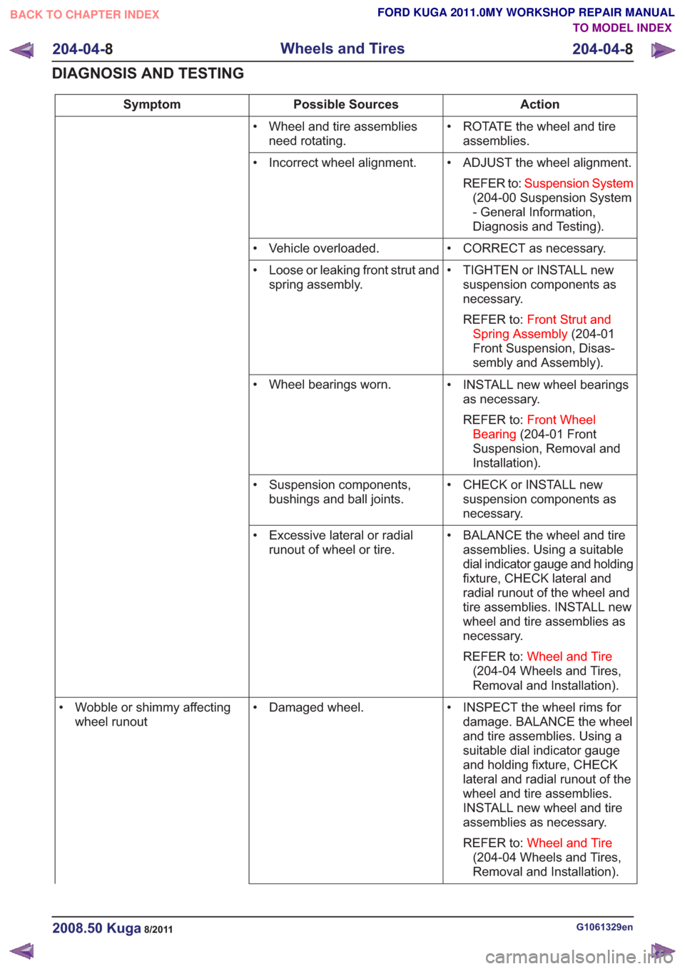
Action
Possible Sources
Symptom
• ROTATE the wheel and tireassemblies.
• Wheel and tire assemblies
need rotating.
• ADJUST the wheel alignment.REFER to: Suspension System
(204-00 Suspension System
- General Information,
Diagnosis and Testing).
• Incorrect wheel alignment.
• CORRECT as necessary.
• Vehicle overloaded.
• TIGHTEN or INSTALL newsuspension components as
necessary.
REFER to: Front Strut and
Spring Assembly (204-01
Front Suspension, Disas-
sembly and Assembly).
• Loose or leaking front strut and
spring assembly.
• INSTALL new wheel bearingsas necessary.
REFER to: Front Wheel
Bearing (204-01 Front
Suspension, Removal and
Installation).
• Wheel bearings worn.
• CHECK or INSTALL newsuspension components as
necessary.
• Suspension components,
bushings and ball joints.
• BALANCE the wheel and tireassemblies. Using a suitable
dial indicator gauge and holding
fixture, CHECK lateral and
radial runout of the wheel and
tire assemblies. INSTALL new
wheel and tire assemblies as
necessary.
REFER to: Wheel and Tire
(204-04 Wheels and Tires,
Removal and Installation).
• Excessive lateral or radial
runout of wheel or tire.
• INSPECT the wheel rims fordamage. BALANCE the wheel
and tire assemblies. Using a
suitable dial indicator gauge
and holding fixture, CHECK
lateral and radial runout of the
wheel and tire assemblies.
INSTALL new wheel and tire
assemblies as necessary.
REFER to: Wheel and Tire
(204-04 Wheels and Tires,
Removal and Installation).
• Damaged wheel.
• Wobble or shimmy affecting
wheel runout
G1061329en2008.50 Kuga8/2011
204-04- 8
Wheels and Tires
204-04- 8
DIAGNOSIS AND TESTING
TO MODEL INDEX
BACK TO CHAPTER INDEX
FORD KUGA 2011.0MY WORKSHOP REPAIR MANUAL
Page 1236 of 2057
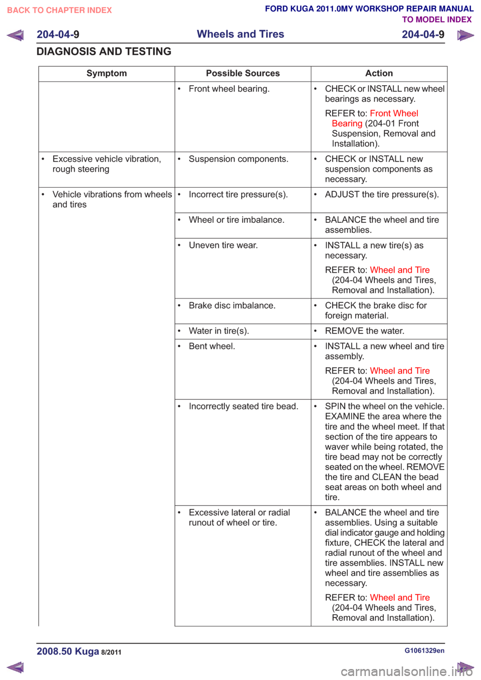
Action
Possible Sources
Symptom
• CHECK or INSTALL new wheelbearings as necessary.
REFER to: Front Wheel
Bearing (204-01 Front
Suspension, Removal and
Installation).
• Front wheel bearing.
• CHECK or INSTALL newsuspension components as
necessary.
• Suspension components.
• Excessive vehicle vibration,
rough steering
• ADJUST the tire pressure(s).
• Incorrect tire pressure(s).
• Vehicle vibrations from wheels
and tires
• BALANCE the wheel and tireassemblies.
• Wheel or tire imbalance.
• INSTALL a new tire(s) asnecessary.
REFER to: Wheel and Tire
(204-04 Wheels and Tires,
Removal and Installation).
• Uneven tire wear.
• CHECK the brake disc forforeign material.
• Brake disc imbalance.
• REMOVE the water.
• Water in tire(s).
• INSTALL a new wheel and tireassembly.
REFER to: Wheel and Tire
(204-04 Wheels and Tires,
Removal and Installation).
• Bent wheel.
• SPIN the wheel on the vehicle.EXAMINE the area where the
tire and the wheel meet. If that
section of the tire appears to
waver while being rotated, the
tire bead may not be correctly
seated on the wheel. REMOVE
the tire and CLEAN the bead
seat areas on both wheel and
tire.
• Incorrectly seated tire bead.
• BALANCE the wheel and tireassemblies. Using a suitable
dial indicator gauge and holding
fixture, CHECK the lateral and
radial runout of the wheel and
tire assemblies. INSTALL new
wheel and tire assemblies as
necessary.
REFER to: Wheel and Tire
(204-04 Wheels and Tires,
Removal and Installation).
• Excessive lateral or radial
runout of wheel or tire.
G1061329en2008.50 Kuga8/2011
204-04- 9
Wheels and Tires
204-04- 9
DIAGNOSIS AND TESTING
TO MODEL INDEX
BACK TO CHAPTER INDEX
FORD KUGA 2011.0MY WORKSHOP REPAIR MANUAL
Page 1237 of 2057
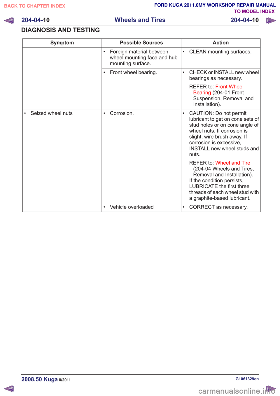
Action
Possible Sources
Symptom
• CLEAN mounting surfaces.
• Foreign material between
wheel mounting face and hub
mounting surface.
• CHECK or INSTALL new wheelbearings as necessary.
REFER to: Front Wheel
Bearing (204-01 Front
Suspension, Removal and
Installation).
• Front wheel bearing.
• CAUTION: Do not permitlubricant to get on cone sets of
stud holes or on cone angle of
wheel nuts. If corrosion is
slight, wire brush away. If
corrosion is excessive,
INSTALL new wheel studs and
nuts.
REFER to: Wheel and Tire
(204-04 Wheels and Tires,
Removal and Installation).
If the condition persists,
LUBRICATE the first three
threads of each wheel stud with
a graphite-based lubricant.
• Corrosion.
• Seized wheel nuts
• CORRECT as necessary.
• Vehicle overloaded
G1061329en2008.50 Kuga8/2011
204-04- 10
Wheels and Tires
204-04- 10
DIAGNOSIS AND TESTING
TO MODEL INDEX
BACK TO CHAPTER INDEX
FORD KUGA 2011.0MY WORKSHOP REPAIR MANUAL
Page 1239 of 2057
SECTION 205-01 Driveshaft
VEHICLE APPLICATION:2008.50 Kuga
PA G E
CONTENTS
REMOVAL AND INSTALLATION
205-01-2
(15 514 0)
Driveshaft ........................................................................\
...............................
205-01-1
Driveshaft
205-01- 1
.
TO MODEL INDEX
BACK TO CHAPTER INDEX
FORD KUGA 2011.0MY WORKSHOP REPAIR MANUAL
Page 1246 of 2057
SECTION 205-02 Rear Drive Axle/Differential
VEHICLE APPLICATION:2008.50 Kuga
PA G E
CONTENTS
DESCRIPTION AND OPERATION
205-02-2
Rear Drive Axle and Differential (Component Location) .....................................................
205-02-6
Rear Drive Axle and Differential (System Operation and Component Description) ...........
205-02-6
System Operation ........................................................................\
.......................................
205-02-6
General Information ........................................................................\
................................
205-02-6
Driving situations ........................................................................\
....................................
205-02-6
Haldex clutch ........................................................................\
..........................................
205-02-7
General overview ........................................................................\
....................................
205-02-7
Operation ........................................................................\
................................................
205-02-7
Design of the 3rd generation Haldex clutch ....................................................................
205-02-9
Design of the multi-plate clutch ........................................................................\
...............
205-02-10
All-wheel drive control unit ........................................................................\
......................
205-02-10
Electric feed pump ........................................................................\
..................................
205-02-10
Pressure control - 3rd generation Haldex clutch .............................................................
205-02-11
Base pressure ........................................................................\
.........................................
205-02-12
Increased base pressure (preload) ........................................................................\
.........
205-02-13
Pressure build-up ........................................................................\
....................................
205-02-14
Design of the 4th generation Haldex clutch ...................................................................
205-02-14
General overview ........................................................................\
....................................
205-02-15
Pressure control - 4th generation Haldex clutch .............................................................
GENERAL PROCEDURES 205-02-17
Differential Fluid Level Check ........................................................................\
.....................
205-02-19
Active On-Demand Coupling Fluid Level Check ................................................................
REMOVAL AND INSTALLATION 205-02-21
Differential Case ........................................................................\
.........................................
205-02-25
Active On-Demand Coupling Module ........................................................................\
.........
205-02-32
Differential Input Shaft Seal ........................................................................\
........................
205-02-38
Differential Support Insulator ........................................................................\
......................
205-02-39
Rear Halfshaft Seal ........................................................................\
.....................................
205-02-41
Drive Pinion Seal ........................................................................\
........................................
DISASSEMBLY AND ASSEMBLY
205-02-42
Active On-Demand Coupling — Vehicles With: 5-Speed Automatic Transaxle - AW55
AWD/6-Speed Automatic Transaxle - 6DCT450 ...............................................................
205-02-1
Rear Drive Axle/Differential
205-02- 1
.
TO MODEL INDEX
BACK TO CHAPTER INDEX
FORD KUGA 2011.0MY WORKSHOP REPAIR MANUAL
Page 1250 of 2057
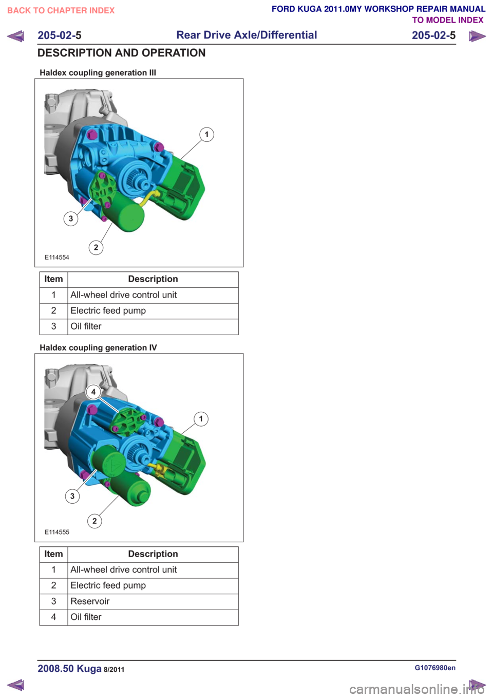
Haldex coupling generation III
1
2
3
E114554
Description
Item
All-wheel drive control unit
1
Electric feed pump
2
Oil filter
3
Haldex coupling generation IV
1
2
3
4
E114555
Description
Item
All-wheel drive control unit
1
Electric feed pump
2
Reservoir
3
Oil filter
4
G1076980en2008.50 Kuga8/2011
205-02- 5
Rear Drive Axle/Differential
205-02- 5
DESCRIPTION AND OPERATION
TO MODEL INDEX
BACK TO CHAPTER INDEX
FORD KUGA 2011.0MY WORKSHOP REPAIR MANUAL
Page 1251 of 2057
Rear Drive Axle and Differential – System Operation andComponent Description
System Operation
General Information
The powertrain with all-wheel drive consists of the
following main components:
• engine
• transaxle with front axle differential
• transfer box
• halfshafts and driveshafts
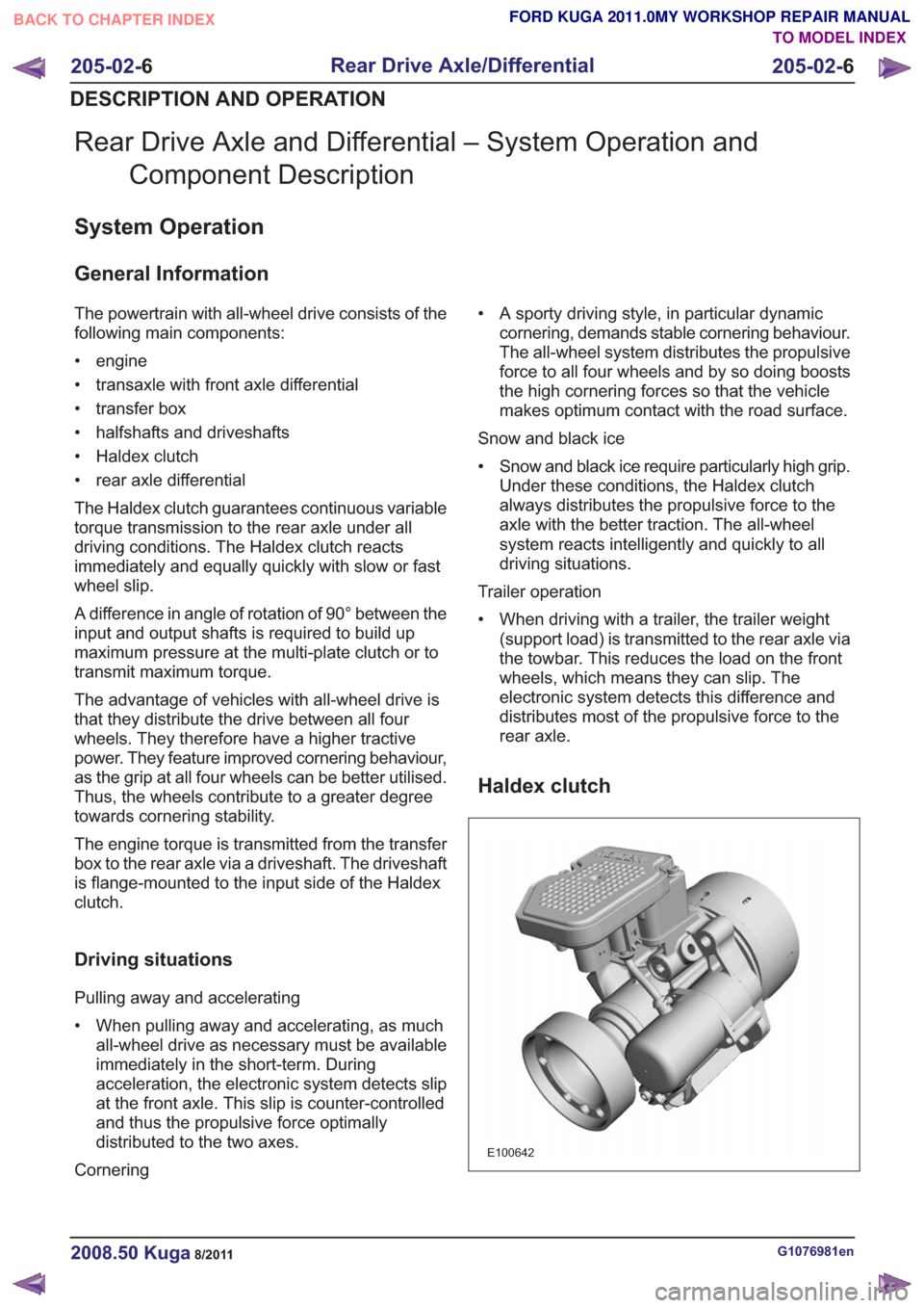
• Haldex clutch
• rear axle differential
The Haldex clutch guarantees continuous variable
torque transmission to the rear axle under all
driving conditions. The Haldex clutch reacts
immediately and equally quickly with slow or fast
wheel slip.
A difference in angle of rotation of 90° between the
input and output shafts is required to build up
maximum pressure at the multi-plate clutch or to
transmit maximum torque.
The advantage of vehicles with all-wheel drive is
that they distribute the drive between all four
wheels. They therefore have a higher tractive
power. They feature improved cornering behaviour,
as the grip at all four wheels can be better utilised.
Thus, the wheels contribute to a greater degree
towards cornering stability.
The engine torque is transmitted from the transfer
box to the rear axle via a driveshaft. The driveshaft
is flange-mounted to the input side of the Haldex
clutch.
Driving situations
Pulling away and accelerating
• When pulling away and accelerating, as muchall-wheel drive as necessary must be available
immediately in the short-term. During
acceleration, the electronic system detects slip
at the front axle. This slip is counter-controlled
and thus the propulsive force optimally
distributed to the two axes.
Cornering • A sporty driving style, in particular dynamic
cornering, demands stable cornering behaviour.
The all-wheel system distributes the propulsive
force to all four wheels and by so doing boosts
the high cornering forces so that the vehicle
makes optimum contact with the road surface.
Snow and black ice
• Snow and black ice require particularly high grip. Under these conditions, the Haldex clutch
always distributes the propulsive force to the
axle with the better traction. The all-wheel
system reacts intelligently and quickly to all
driving situations.
Trailer operation
• When driving with a trailer, the trailer weight (support load) is transmitted to the rear axle via
the towbar. This reduces the load on the front
wheels, which means they can slip. The
electronic system detects this difference and
distributes most of the propulsive force to the
rear axle.
Haldex clutch
E100642
G1076981en2008.50 Kuga8/2011
205-02- 6
Rear Drive Axle/Differential
205-02- 6
DESCRIPTION AND OPERATION
TO MODEL INDEX
BACK TO CHAPTER INDEX
FORD KUGA 2011.0MY WORKSHOP REPAIR MANUAL