2011 FORD KUGA remove pcm
[x] Cancel search: remove pcmPage 1525 of 2057
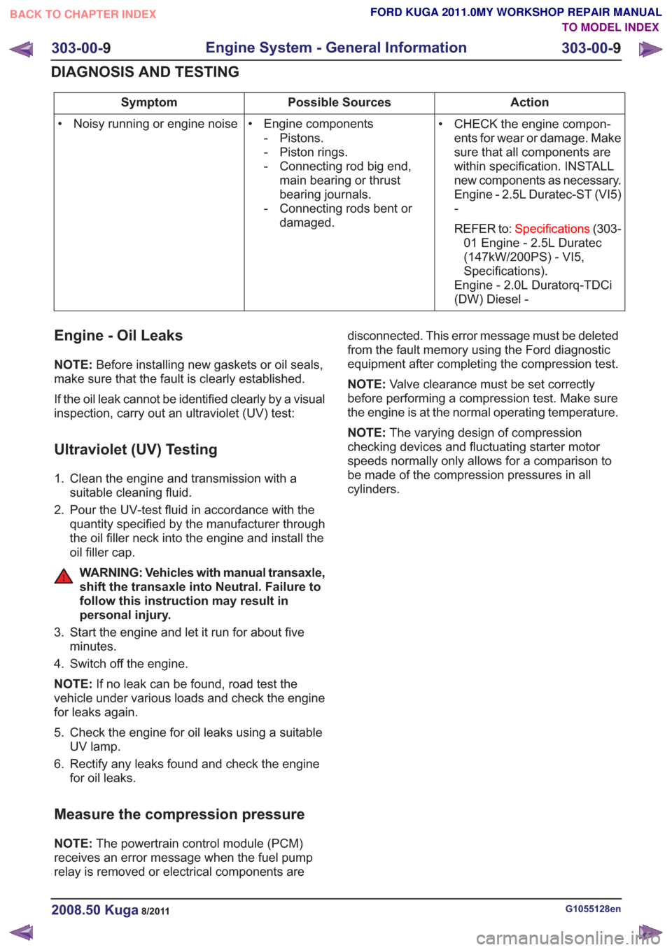
Action
Possible Sources
Symptom
• CHECK the engine compon-ents for wear or damage. Make
sure that all components are
within specification. INSTALL
new components as necessary.
Engine - 2.5L Duratec-ST (VI5)
-
REFER to: Specifications (303-
01 Engine - 2.5L Duratec
(147kW/200PS) - VI5,
Specifications).
Engine - 2.0L Duratorq-TDCi
(DW) Diesel -
• Engine components
- Pistons.
- Piston rings.
- Connecting rod big end,main bearing or thrust
bearing journals.
- Connecting rods bent or damaged.
• Noisy running or engine noise
Engine - Oil Leaks
NOTE:
Before installing new gaskets or oil seals,
make sure that the fault is clearly established.
If the oil leak cannot be identified clearly by a visual
inspection, carry out an ultraviolet (UV) test:
Ultraviolet (UV) Testing
1. Clean the engine and transmission with a suitable cleaning fluid.
2. Pour the UV-test fluid in accordance with the quantity specified by the manufacturer through
the oil filler neck into the engine and install the
oil filler cap.
WARNING: Vehicles with manual transaxle,
shift the transaxle into Neutral. Failure to
follow this instruction may result in
personal injury.
3. Start the engine and let it run for about five minutes.
4. Switch off the engine.
NOTE: If no leak can be found, road test the
vehicle under various loads and check the engine
for leaks again.
5. Check the engine for oil leaks using a suitable UV lamp.
6. Rectify any leaks found and check the engine for oil leaks.
Measure the compression pressure
NOTE: The powertrain control module (PCM)
receives an error message when the fuel pump
relay is removed or electrical components are disconnected. This error message must be deleted
from the fault memory using the Ford diagnostic
equipment after completing the compression test.
NOTE:
Valve clearance must be set correctly
before performing a compression test. Make sure
the engine is at the normal operating temperature.
NOTE: The varying design of compression
checking devices and fluctuating starter motor
speeds normally only allows for a comparison to
be made of the compression pressures in all
cylinders.
G1055128en2008.50 Kuga8/2011
303-00- 9
Engine System - General Information
303-00- 9
DIAGNOSIS AND TESTING
TO MODEL INDEX
BACK TO CHAPTER INDEX
FORD KUGA 2011.0MY WORKSHOP REPAIR MANUAL
Page 1530 of 2057
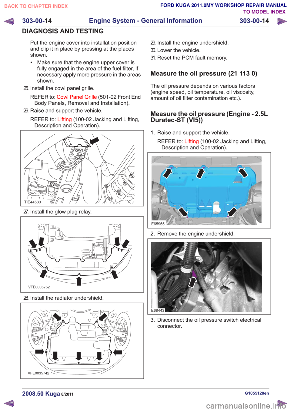
Put the engine cover into installation position
and clip it in place by pressing at the places
shown.• Make sure that the engine upper cover is fully engaged in the area of the fuel filter, if
necessary apply more pressure in the areas
shown.
25. Install the cowl panel grille.
REFER to: Cowl Panel Grille (501-02 Front End
Body Panels, Removal and Installation).
26. Raise and support the vehicle.
REFER to: Lifting(100-02 Jacking and Lifting,
Description and Operation).
TIE44583
27. Install the glow plug relay.
VFE0035752
28. Install the radiator undershield.
VFE0035742
29. Install the engine undershield.
30. Lower the vehicle.
31. Reset the PCM fault memory.
Measure the oil pressure (21 113 0)
The oil pressure depends on various factors
(engine speed, oil temperature, oil viscosity,
amount of oil filter contamination etc.).
Measure the oil pressure (Engine - 2.5L
Duratec-ST (VI5))
1. Raise and support the vehicle.
REFER to: Lifting(100-02 Jacking and Lifting,
Description and Operation).
E65955
2. Remove the engine undershield.
E68443
3. Disconnect the oil pressure switch electrical connector.
G1055128en2008.50 Kuga8/2011
303-00- 14
Engine System - General Information
303-00- 14
DIAGNOSIS AND TESTING
TO MODEL INDEX
BACK TO CHAPTER INDEX
FORD KUGA 2011.0MY WORKSHOP REPAIR MANUAL
Page 1595 of 2057
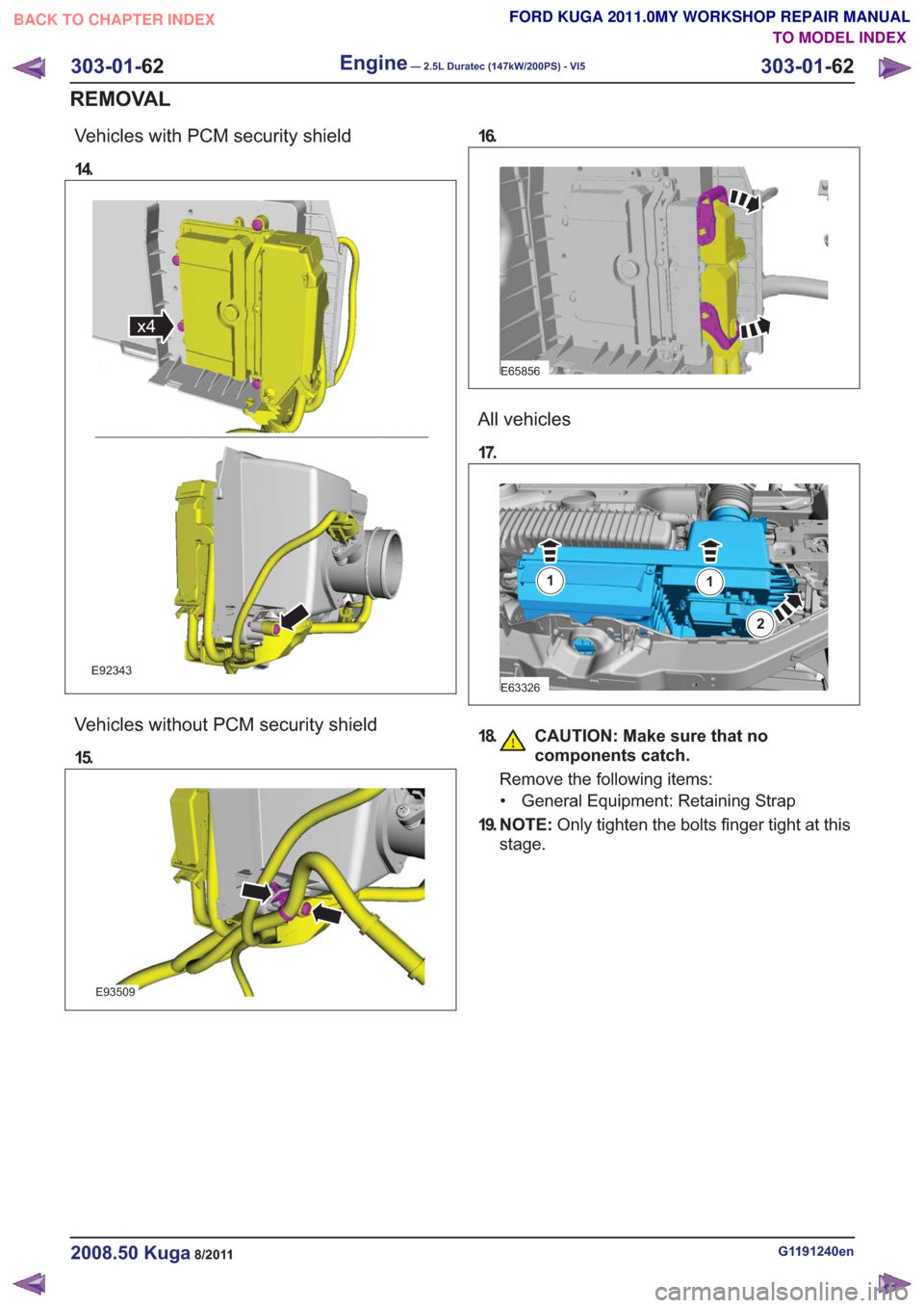
Vehicles with PCM security shield
14.
x4x4
E92343
Vehicles without PCM security shield
15.
E93509
16.
E65856
All vehicles
17.
E63326
11
2
18. CAUTION: Make sure that nocomponents catch.
Remove the following items:
• General Equipment: Retaining Strap
19. N O T E : Only tighten the bolts finger tight at this
stage.
G1191240en2008.50 Kuga8/2011
303-01- 62
Engine— 2.5L Duratec (147kW/200PS) - VI5303-01-
62
REMOVAL
TO MODEL INDEX
BACK TO CHAPTER INDEX
FORD KUGA 2011.0MY WORKSHOP REPAIR MANUAL
Page 1668 of 2057
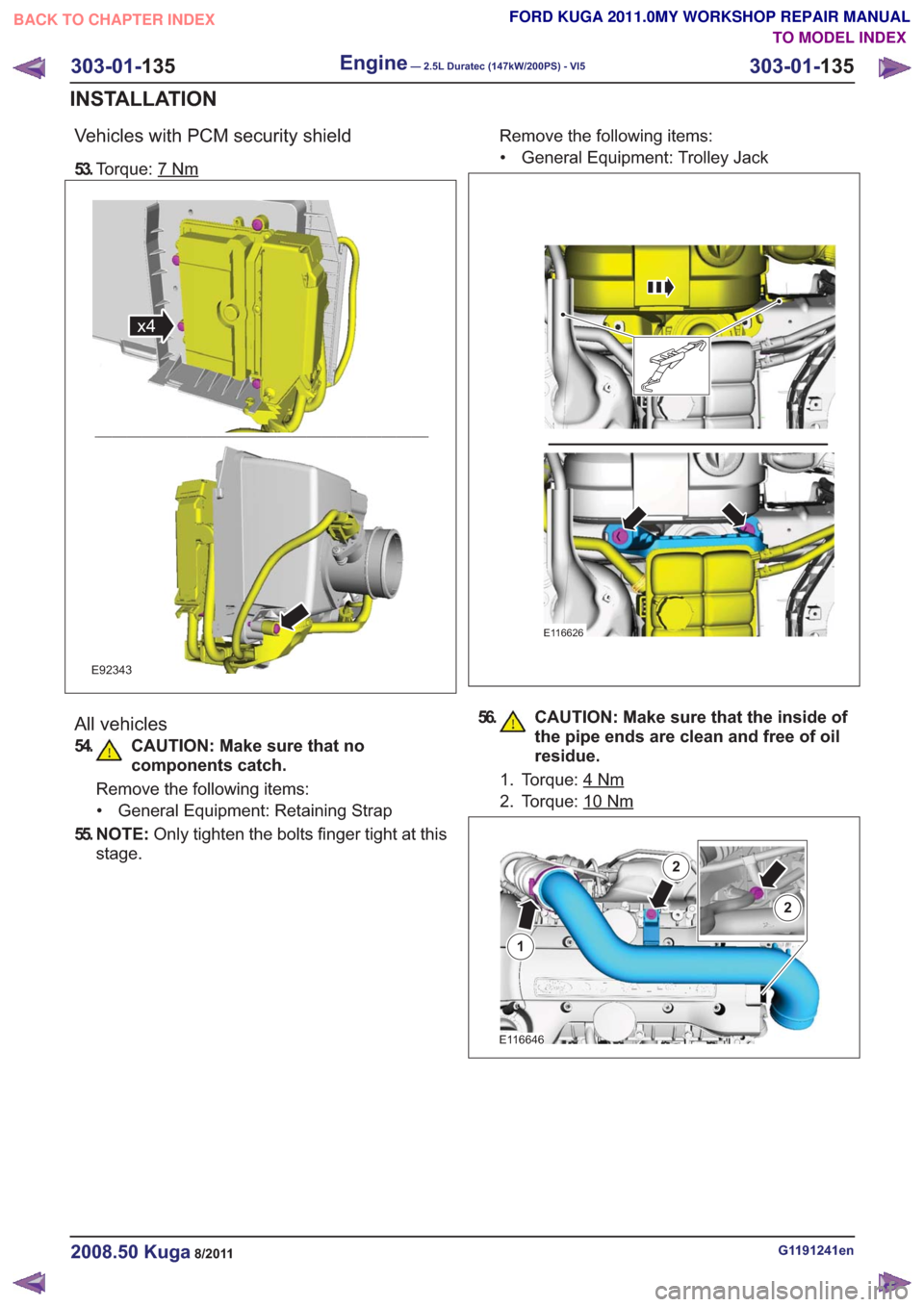
Vehicles with PCM security shield
53.Torque: 7Nm
x4x4
E92343
All vehicles
54. CAUTION: Make sure that no
components catch.
Remove the following items:
• General Equipment: Retaining Strap
55. N O T E : Only tighten the bolts finger tight at this
stage. Remove the following items:
• General Equipment: Trolley Jack
E116626
56. CAUTION: Make sure that the inside of the pipe ends are clean and free of oil
residue.
1. Torque: 4Nm
2. Torque: 10Nm
E116646
1
2
2
G1191241en2008.50 Kuga8/2011
303-01- 135
Engine— 2.5L Duratec (147kW/200PS) - VI5303-01-
135
INSTALLATION
TO MODEL INDEX
BACK TO CHAPTER INDEX
FORD KUGA 2011.0MY WORKSHOP REPAIR MANUAL
Page 1698 of 2057
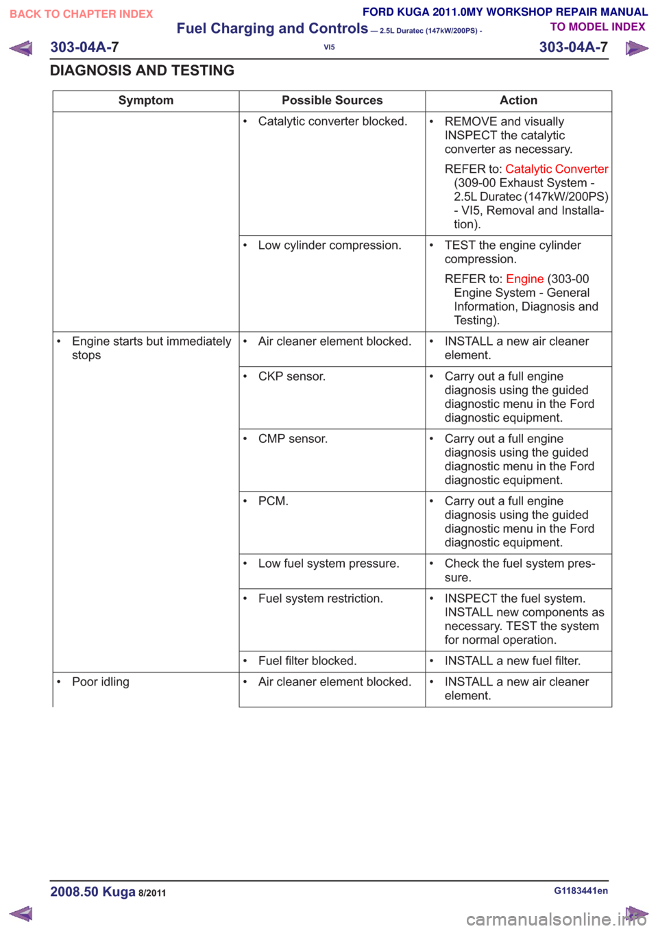
Action
Possible Sources
Symptom
• REMOVE and visuallyINSPECT the catalytic
converter as necessary.
REFER to: Catalytic Converter
(309-00 Exhaust System -
2.5L Duratec (147kW/200PS)
- VI5, Removal and Installa-
tion).
• Catalytic converter blocked.
• TEST the engine cylindercompression.
REFER to: Engine(303-00
Engine System - General
Information, Diagnosis and
Testing).
• Low cylinder compression.
• INSTALL a new air cleanerelement.
• Air cleaner element blocked.
• Engine starts but immediately
stops
• Carry out a full enginediagnosis using the guided
diagnostic menu in the Ford
diagnostic equipment.
• CKP sensor.
• Carry out a full enginediagnosis using the guided
diagnostic menu in the Ford
diagnostic equipment.
• CMP sensor.
• Carry out a full enginediagnosis using the guided
diagnostic menu in the Ford
diagnostic equipment.
•PCM.
• Check the fuel system pres-sure.
• Low fuel system pressure.
• INSPECT the fuel system.INSTALL new components as
necessary. TEST the system
for normal operation.
• Fuel system restriction.
• INSTALL a new fuel filter.
• Fuel filter blocked.
• INSTALL a new air cleanerelement.
• Air cleaner element blocked.
• Poor idling
G1183441en2008.50 Kuga8/2011
303-04A- 7
Fuel Charging and Controls
— 2.5L Duratec (147kW/200PS) -
VI5
303-04A- 7
DIAGNOSIS AND TESTING
TO MODEL INDEX
BACK TO CHAPTER INDEX
FORD KUGA 2011.0MY WORKSHOP REPAIR MANUAL
Page 1782 of 2057
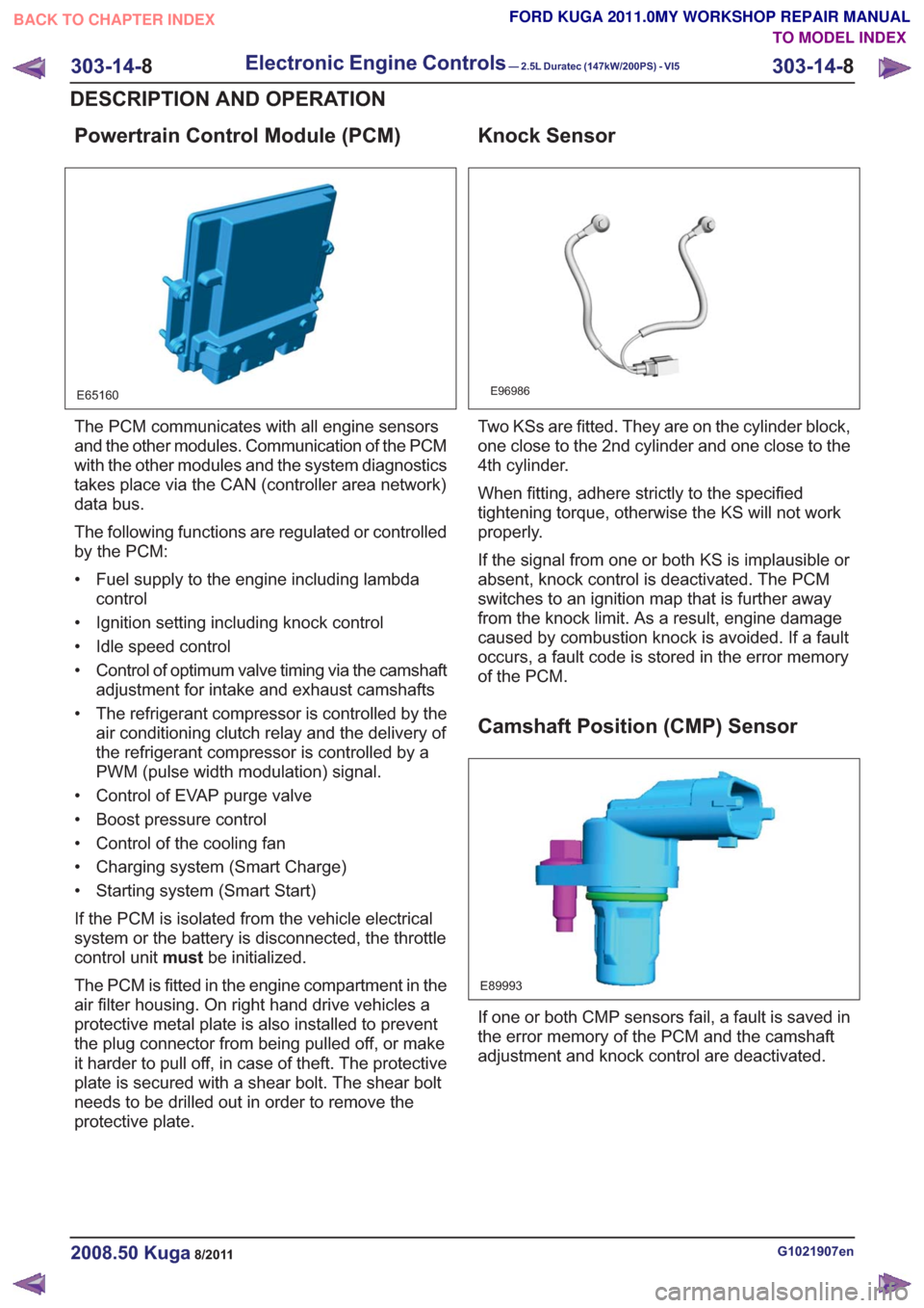
Powertrain Control Module (PCM)
E65160
The PCM communicates with all engine sensors
and the other modules. Communication of the PCM
with the other modules and the system diagnostics
takes place via the CAN (controller area network)
data bus.
The following functions are regulated or controlled
by the PCM:
• Fuel supply to the engine including lambdacontrol
• Ignition setting including knock control
• Idle speed control
• Control of optimum valve timing via the camshaft adjustment for intake and exhaust camshafts
• The refrigerant compressor is controlled by the air conditioning clutch relay and the delivery of
the refrigerant compressor is controlled by a
PWM (pulse width modulation) signal.
• Control of EVAP purge valve
• Boost pressure control
• Control of the cooling fan
• Charging system (Smart Charge)
• Starting system (Smart Start)
If the PCM is isolated from the vehicle electrical
system or the battery is disconnected, the throttle
control unit mustbe initialized.
The PCM is fitted in the engine compartment in the
air filter housing. On right hand drive vehicles a
protective metal plate is also installed to prevent
the plug connector from being pulled off, or make
it harder to pull off, in case of theft. The protective
plate is secured with a shear bolt. The shear bolt
needs to be drilled out in order to remove the
protective plate.
Knock Sensor
E96986
Two KSs are fitted. They are on the cylinder block,
one close to the 2nd cylinder and one close to the
4th cylinder.
When fitting, adhere strictly to the specified
tightening torque, otherwise the KS will not work
properly.
If the signal from one or both KS is implausible or
absent, knock control is deactivated. The PCM
switches to an ignition map that is further away
from the knock limit. As a result, engine damage
caused by combustion knock is avoided. If a fault
occurs, a fault code is stored in the error memory
of the PCM.
Camshaft Position (CMP) Sensor
E89993
If one or both CMP sensors fail, a fault is saved in
the error memory of the PCM and the camshaft
adjustment and knock control are deactivated.
G1021907en2008.50 Kuga8/2011
303-14- 8
Electronic Engine Controls— 2.5L Duratec (147kW/200PS) - VI5303-14-
8
DESCRIPTION AND OPERATION
TO MODEL INDEX
BACK TO CHAPTER INDEX
FORD KUGA 2011.0MY WORKSHOP REPAIR MANUAL
Page 1797 of 2057
Calculation of valve timing adjustment
angle
The 2.5L Duratec (VI5) engine has two camshaft
adjustment units which work independently of each
other.
One camshaft adjustment solenoid is installed for
each intake camshaft and exhaust camshaft.
This allows the PCM to continuously adjust the
intake and exhaust-side camshaft adjustments
independently of one another. The timing is
adjusted by the PCM using curves; adjustment is
primarily done as a function of engine load and
engine speed.
In this way the engine performance is increased
and internal exhaust gas recirculation is realized.
The advantages of camshaft adjustment are as
follows:
• Higher torque and improved torquecharacteristics
• Reduced fuel consumption
• Improved emissions performance
The camshaft adjustment solenoids are actuated
by the PWM by means of a PCM signal.
Continuous adjustment of the camshafts by the
PCM is achieved by means of the camshaft
adjustment solenoids, the camshaft adjustment
units and two CMP sensors. A defined quantity of
engine is oil is supplied to or drained from the
adjustment units via the camshaft adjustment
solenoids. The existing EOP (engine oil pressure)
is taken into account in the process. In this way
the valve timings are adjusted according to the
operating condition of the engine. The camshaft
adjusters work according to the vane-cell principle.
On starting the engine, both camshafts are
mechanically locked in their starting positions. The
intake camshaft is in the maximum late position
and the exhaust camshaft in the maximum early
position.
Control is divided into four main areas:
• Low engine speed and low load
• Partial load
• Low engine speed and high load
• High engine speed and high load
At low engine speed and low load, the exhaust
valves open early and the intake valves open late.
The result is reduced fuel consumption and more
uniform idling. In the partial load range, the exhaust valves and
the intake valves open late. The late opening of
the exhaust valves results in a good utilization of
the expanding gases in the cylinder. Closing the
exhaust valves after Top Dead Center allows
internal exhaust gas recirculation through aspiration
of exhaust gases into the combustion chamber.
Moreover, the intake valves close after Bottom
Dead Centre, allowing the fresh air/fuel mixture
and exhaust gases to flow back into the intake
tract. The result is reduced fuel consumption and
low emissions.
At low engine speed and high engine load, the
exhaust valves open late and the intake valves
open early. Due to the resulting valve opening
overlap at Top Dead Centre, the pulsating gas
column within the combustion chamber is utilized
to achieve better charging of the combustion
chamber. The result is increased torque at lower
RPM.
At high engine speeds and high engine load, the
exhaust valves open early and the intake valves
close late. Because a rapid gas exchange must be
achieved at high engine speeds, the early opening
of the exhaust valves achieves better expulsion of
the exhaust gas and the late closing of the intake
valves improves cylinder charge efficiency.
Optimum power output is achieved.
Many other camshaft positions are possible in
addition to these settings.
In order to avoid a malfunction in the camshaft
adjustment units at excessively low ambient or
engine-oil temperatures, they are activated by the
PCM with a time delay via the camshaft adjustment
solenoids. The PCM receives the information
required for this from the ECT sensor and the
outside air temperature sensor.
When idling and during deceleration, the camshaft
adjustment solenoids are activated repeatedly by
the PCM in order to remove any dirt which may be
on the bore holes and ring grooves.
Boost pressure control
Optimum regulation is achieved by means of an
electronically-controlled solenoid valve, the boost
control solenoid valve.
Refer to:
Turbocharger (303-04 Fuel Charging and
Controls - Turbocharger - 2.5L Duratec
(147kW/200PS) - VI5, Description and
Operation).
G1021908en2008.50 Kuga8/2011
303-14- 23
Electronic Engine Controls— 2.5L Duratec (147kW/200PS) - VI5303-14-
23
DESCRIPTION AND OPERATION
TO MODEL INDEX
BACK TO CHAPTER INDEX
FORD KUGA 2011.0MY WORKSHOP REPAIR MANUAL
Page 2005 of 2057
Speed Control – Overview
Speed Control
The cruise control system keeps the vehicle to a
target speed selected by the driver. The cruise
control system is controlled by the PCM (powertrain
control module)
WARNING: The cruise control system may
not be used in heavy traffic, on winding
roads or on a slippery road surface.
To remove the buttons for the cruise control
system, the airbag must be removed. The buttons
for the two control switch units cannot be replaced
individually.
G1015505en2008.50 Kuga8/2011
310-03- 2
Speed Control
310-03- 2
DESCRIPTION AND OPERATION
TO MODEL INDEX
BACK TO CHAPTER INDEX
FORD KUGA 2011.0MY WORKSHOP REPAIR MANUAL