2011 FORD KUGA Oil specification
[x] Cancel search: Oil specificationPage 1283 of 2057
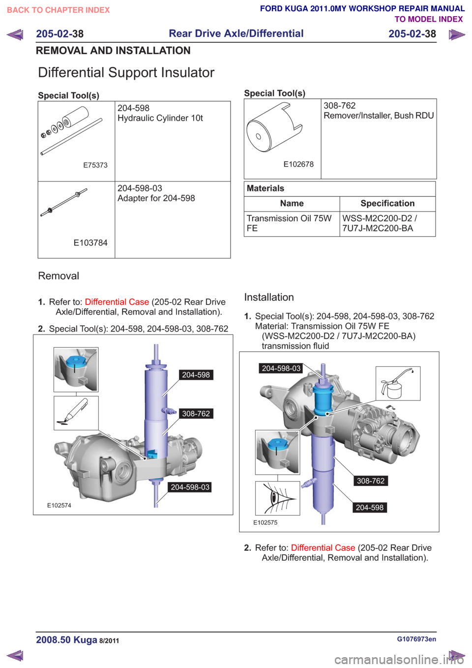
Differential Support Insulator
Special Tool(s)204-598
Hydraulic Cylinder 10t
E75373
204-598-03
Adapter for 204-598
E103784
Special Tool(s)308-762
Remover/Installer, Bush RDU
E102678
Materials
Specification
Name
WSS-M2C200-D2 /
7U7J-M2C200-BA
Transmission Oil 75W
FE
Removal
1.
Refer to: Differential Case (205-02 Rear Drive
Axle/Differential, Removal and Installation).
2. Special Tool(s): 204-598, 204-598-03, 308-762
308-762
204-598
204-598-03
308-762
204-598
204-598-03
E102574
Installation
1.Special Tool(s): 204-598, 204-598-03, 308-762
Material: Transmission Oil 75W FE
(WSS-M2C200-D2 / 7U7J-M2C200-BA)
transmission fluid
308-762
204-598
204-598-03
308-762
204-598
204-598-03
E102575
2. Refer to: Differential Case (205-02 Rear Drive
Axle/Differential, Removal and Installation).
G1076973en2008.50 Kuga8/2011
205-02- 38
Rear Drive Axle/Differential
205-02- 38
REMOVAL AND INSTALLATION
TO MODEL INDEX
BACK TO CHAPTER INDEX
FORD KUGA 2011.0MY WORKSHOP REPAIR MANUAL
Page 1287 of 2057
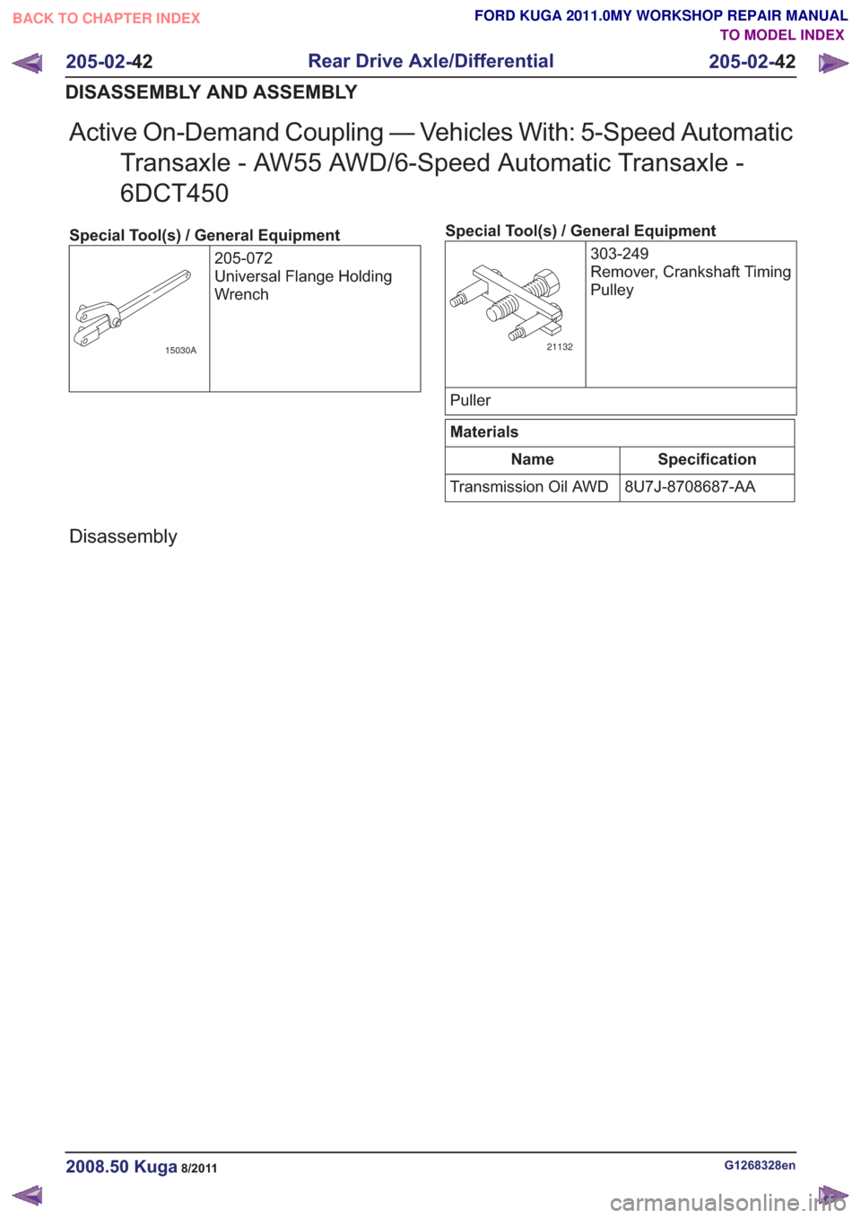
Active On-Demand Coupling — Vehicles With: 5-Speed AutomaticTransaxle - AW55 AWD/6-Speed Automatic Transaxle -
6DCT450
Special Tool(s) / General Equipment
205-072
Universal Flange Holding
Wrench
15030A
Special Tool(s) / General Equipment303-249
Remover, Crankshaft Timing
Pulley
21132
Puller
Materials
Specification
Name
8U7J-8708687-AA
Transmission Oil AWD
Disassembly
G1268328en2008.50 Kuga8/2011
205-02- 42
Rear Drive Axle/Differential
205-02- 42
DISASSEMBLY AND ASSEMBLY
TO MODEL INDEX
BACK TO CHAPTER INDEX
FORD KUGA 2011.0MY WORKSHOP REPAIR MANUAL
Page 1379 of 2057
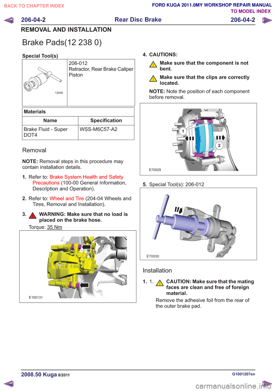
Brake Pads(12 238 0)
Special Tool(s)206-012
Retractor, Rear Brake Caliper
Piston
12006
Materials
Specification
Name
WSS-M6C57-A2
Brake Fluid - Super
DOT4
Removal
NOTE: Removal steps in this procedure may
contain installation details.
1. Refer to: Brake System Health and Safety
Precautions (100-00 General Information,
Description and Operation).
2. Refer to: Wheel and Tire (204-04 Wheels and
Tires, Removal and Installation).
3. WARNING: Make sure that no load is placed on the brake hose.
Torque: 35Nm
E100131
4. CAUTIONS:
Make sure that the component is not
bent.
Make sure that the clips are correctly
located.
NOTE: Note the position of each component
before removal.
E70029
1
2
5. Special Tool(s): 206-012
E70030
Installation
1. 1. CAUTION: Make sure that the mating
faces are clean and free of foreign
material.
Remove the adhesive foil from the rear of
the outer brake pad.
G1001207en2008.50 Kuga8/2011
206-04- 2
Rear Disc Brake
206-04- 2
REMOVAL AND INSTALLATION
TO MODEL INDEX
BACK TO CHAPTER INDEX
FORD KUGA 2011.0MY WORKSHOP REPAIR MANUAL
Page 1518 of 2057
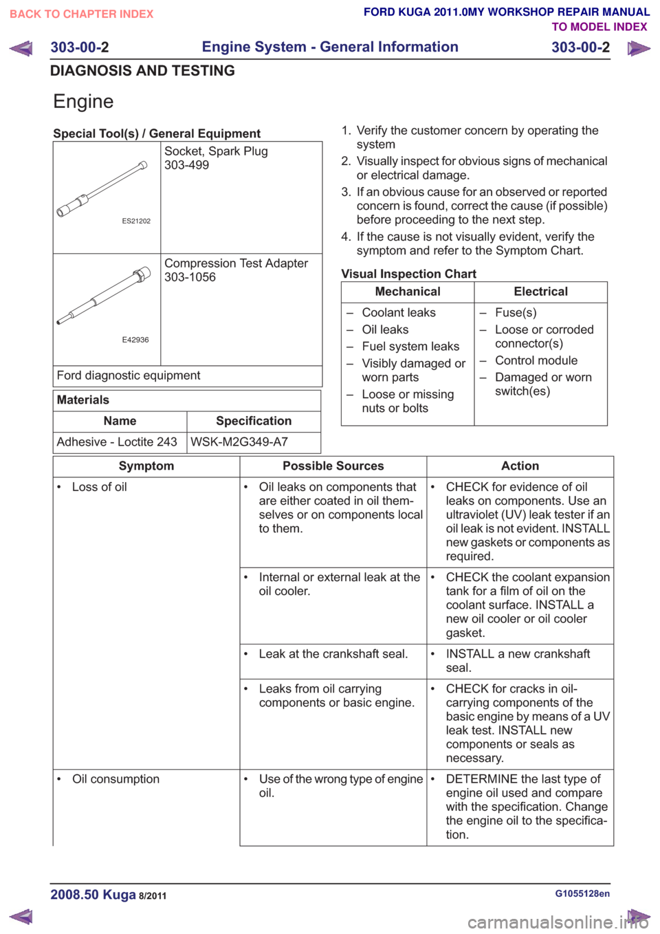
Engine
Special Tool(s) / General EquipmentSocket, Spark Plug
303-499
ES21202
Compression Test Adapter
303-1056
E42936
Ford diagnostic equipment
Materials
Specification
Name
WSK-M2G349-A7
Adhesive - Loctite 243 1. Verify the customer concern by operating the
system
2. Visually inspect for obvious signs of mechanical or electrical damage.
3. If an obvious cause for an observed or reported concern is found, correct the cause (if possible)
before proceeding to the next step.
4. If the cause is not visually evident, verify the symptom and refer to the Symptom Chart.
Visual Inspection Chart
Electrical
Mechanical
– Fuse(s)
– Loose or corrodedconnector(s)
– Control module
– Damaged or worn switch(es)
– Coolant leaks
– Oil leaks
– Fuel system leaks
– Visibly damaged or
worn parts
– Loose or missing nuts or bolts
Action
Possible Sources
Symptom
• CHECK for evidence of oilleaks on components. Use an
ultraviolet (UV) leak tester if an
oil leak is not evident. INSTALL
new gaskets or components as
required.
• Oil leaks on components that
are either coated in oil them-
selves or on components local
to them.
• Loss of oil
• CHECK the coolant expansiontank for a film of oil on the
coolant surface. INSTALL a
new oil cooler or oil cooler
gasket.
• Internal or external leak at the
oil cooler.
• INSTALL a new crankshaftseal.
• Leak at the crankshaft seal.
• CHECK for cracks in oil-carrying components of the
basic engine by means of a UV
leak test. INSTALL new
components or seals as
necessary.
• Leaks from oil carrying
components or basic engine.
• DETERMINE the last type ofengine oil used and compare
with the specification. Change
the engine oil to the specifica-
tion.
• Use of the wrong type of engine
oil.
• Oil consumption
G1055128en2008.50 Kuga8/2011
303-00-
2
Engine System - General Information
303-00- 2
DIAGNOSIS AND TESTING
TO MODEL INDEX
BACK TO CHAPTER INDEX
FORD KUGA 2011.0MY WORKSHOP REPAIR MANUAL
Page 1525 of 2057
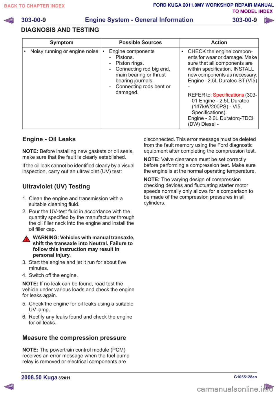
Action
Possible Sources
Symptom
• CHECK the engine compon-ents for wear or damage. Make
sure that all components are
within specification. INSTALL
new components as necessary.
Engine - 2.5L Duratec-ST (VI5)
-
REFER to: Specifications (303-
01 Engine - 2.5L Duratec
(147kW/200PS) - VI5,
Specifications).
Engine - 2.0L Duratorq-TDCi
(DW) Diesel -
• Engine components
- Pistons.
- Piston rings.
- Connecting rod big end,main bearing or thrust
bearing journals.
- Connecting rods bent or damaged.
• Noisy running or engine noise
Engine - Oil Leaks
NOTE:
Before installing new gaskets or oil seals,
make sure that the fault is clearly established.
If the oil leak cannot be identified clearly by a visual
inspection, carry out an ultraviolet (UV) test:
Ultraviolet (UV) Testing
1. Clean the engine and transmission with a suitable cleaning fluid.
2. Pour the UV-test fluid in accordance with the quantity specified by the manufacturer through
the oil filler neck into the engine and install the
oil filler cap.
WARNING: Vehicles with manual transaxle,
shift the transaxle into Neutral. Failure to
follow this instruction may result in
personal injury.
3. Start the engine and let it run for about five minutes.
4. Switch off the engine.
NOTE: If no leak can be found, road test the
vehicle under various loads and check the engine
for leaks again.
5. Check the engine for oil leaks using a suitable UV lamp.
6. Rectify any leaks found and check the engine for oil leaks.
Measure the compression pressure
NOTE: The powertrain control module (PCM)
receives an error message when the fuel pump
relay is removed or electrical components are disconnected. This error message must be deleted
from the fault memory using the Ford diagnostic
equipment after completing the compression test.
NOTE:
Valve clearance must be set correctly
before performing a compression test. Make sure
the engine is at the normal operating temperature.
NOTE: The varying design of compression
checking devices and fluctuating starter motor
speeds normally only allows for a comparison to
be made of the compression pressures in all
cylinders.
G1055128en2008.50 Kuga8/2011
303-00- 9
Engine System - General Information
303-00- 9
DIAGNOSIS AND TESTING
TO MODEL INDEX
BACK TO CHAPTER INDEX
FORD KUGA 2011.0MY WORKSHOP REPAIR MANUAL
Page 1534 of 2057
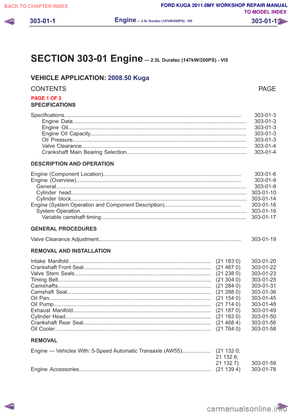
SECTION 303-01 Engine— 2.5L Duratec (147kW/200PS) - VI5
VEHICLE APPLICATION:2008.50 Kuga
PA G E
CONTENTS
SPECIFICATIONS
303-01-3
Specifications ........................................................................\
..............................................
303-01-3
Engine Data ........................................................................\
............................................
303-01-3
Engine Oil ........................................................................\
...............................................
303-01-3
Engine Oil Capacity ........................................................................\
................................
303-01-3
Oil Pressure ........................................................................\
............................................
303-01-4
Valve Clearance ........................................................................\
......................................
303-01-4
Crankshaft Main Bearing Selection ........................................................................\
........
DESCRIPTION AND OPERATION 303-01-6
Engine (Component Location) ........................................................................\
....................
303-01-9
Engine (Overview) ........................................................................\
......................................
303-01-9
General ........................................................................\
.......................................................
303-01-10
Cylinder head ........................................................................\
.............................................
303-01-14
Cylinder block ........................................................................\
.............................................
303-01-16
Engine (System Operation and Component Description) ...................................................
303-01-16
System Operation ........................................................................\
.......................................
303-01-17
Variable camshaft timing ........................................................................\
.........................
GENERAL PROCEDURES 303-01-19
Valve Clearance Adjustment ........................................................................\
.......................
REMOVAL AND INSTALLATION 303-01-20
(21 183 0)
Intake Manifold ........................................................................\
.......................
303-01-22
(21 467 0)
Crankshaft Front Seal ........................................................................\
.............
303-01-23
(21 238 0)
Valve Stem Seals ........................................................................\
...................
303-01-25
(21 304 0)
Timing Belt ........................................................................\
..............................
303-01-31
(21 284 0)
Camshafts ........................................................................\
..............................
303-01-36
(21 288 0)
Camshaft Seal ........................................................................\
........................
303-01-45
(21 154 0)
Oil Pan ........................................................................\
....................................
303-01-48
(21 714 0)
Oil Pump ........................................................................\
.................................
303-01-49
(21 187 0)
Exhaust Manifold ........................................................................\
....................
303-01-50
(21 163 0)
Cylinder Head ........................................................................\
.........................
303-01-56
(21 468 4)
Crankshaft Rear Seal ........................................................................\
.............
303-01-58
(21 764 0)
Oil Cooler ........................................................................\
................................
REMOVAL
303-01-59
(21
132 0;
21 132 6;
21 132 7)
Engine — Vehicles With: 5-Speed Automatic Transaxle (AW55)
...................
303-01-78
(21 139 4)
Engine Accessories ........................................................................\
................
303-01-1
Engine— 2.5L Duratec (147kW/200PS) - VI5303-01-
1
.
TO MODEL INDEX
BACK TO CHAPTER INDEX
PAGE 1 OF 2 FORD KUGA 2011.0MY WORKSHOP REPAIR MANUAL
Page 1536 of 2057
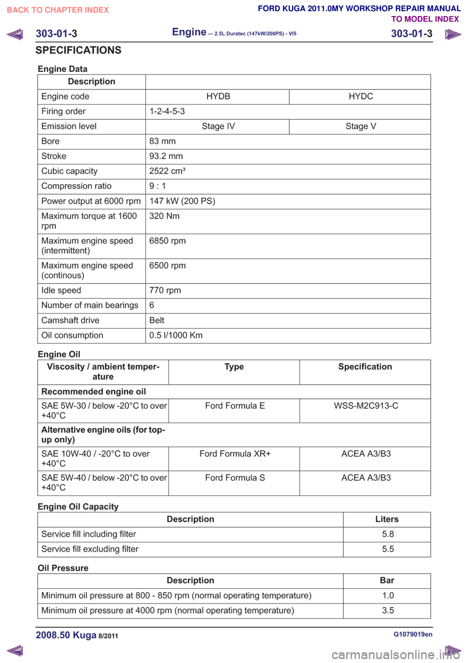
Engine Data
DescriptionHYDC
HYDB
Engine code
1-2-4-5-3
Firing order
Stage V
Stage IV
Emission level
83 mm
Bore
93.2 mm
Stroke
2522 cm³
Cubic capacity
9:1
Compression ratio
147 kW (200 PS)
Power output at 6000 rpm
320 Nm
Maximum torque at 1600
rpm
6850 rpm
Maximum engine speed
(intermittent)
6500 rpm
Maximum engine speed
(continous)
770 rpm
Idle speed
6
Number of main bearings
Belt
Camshaft drive
0.5 l/1000 Km
Oil consumption
Engine Oil
Specification
Ty p e
Viscosity / ambient temper-
ature
Recommended engine oil WSS-M2C913-C
Ford Formula E
SAE 5W-30 / below -20°C to over
+40°C
Alternative engine oils (for top-
up only)
ACEA A3/B3
Ford Formula XR+
SAE 10W-40 / -20°C to over
+40°C
ACEA A3/B3
Ford Formula S
SAE 5W-40 / below -20°C to over
+40°C
Engine Oil Capacity
Liters
Description
5.8
Service fill including filter
5.5
Service fill excluding filter
Oil Pressure
Bar
Description
1.0
Minimum oil pressure at 800 - 850 rpm (normal operating temperature)
3.5
Minimum oil pressure at 4000 rpm (normal operating temperature)
G1079019en2008.50 Kuga8/2011
303-01- 3
Engine— 2.5L Duratec (147kW/200PS) - VI5303-01-
3
SPECIFICATIONS
TO MODEL INDEX
BACK TO CHAPTER INDEX
FORD KUGA 2011.0MY WORKSHOP REPAIR MANUAL
Page 1537 of 2057
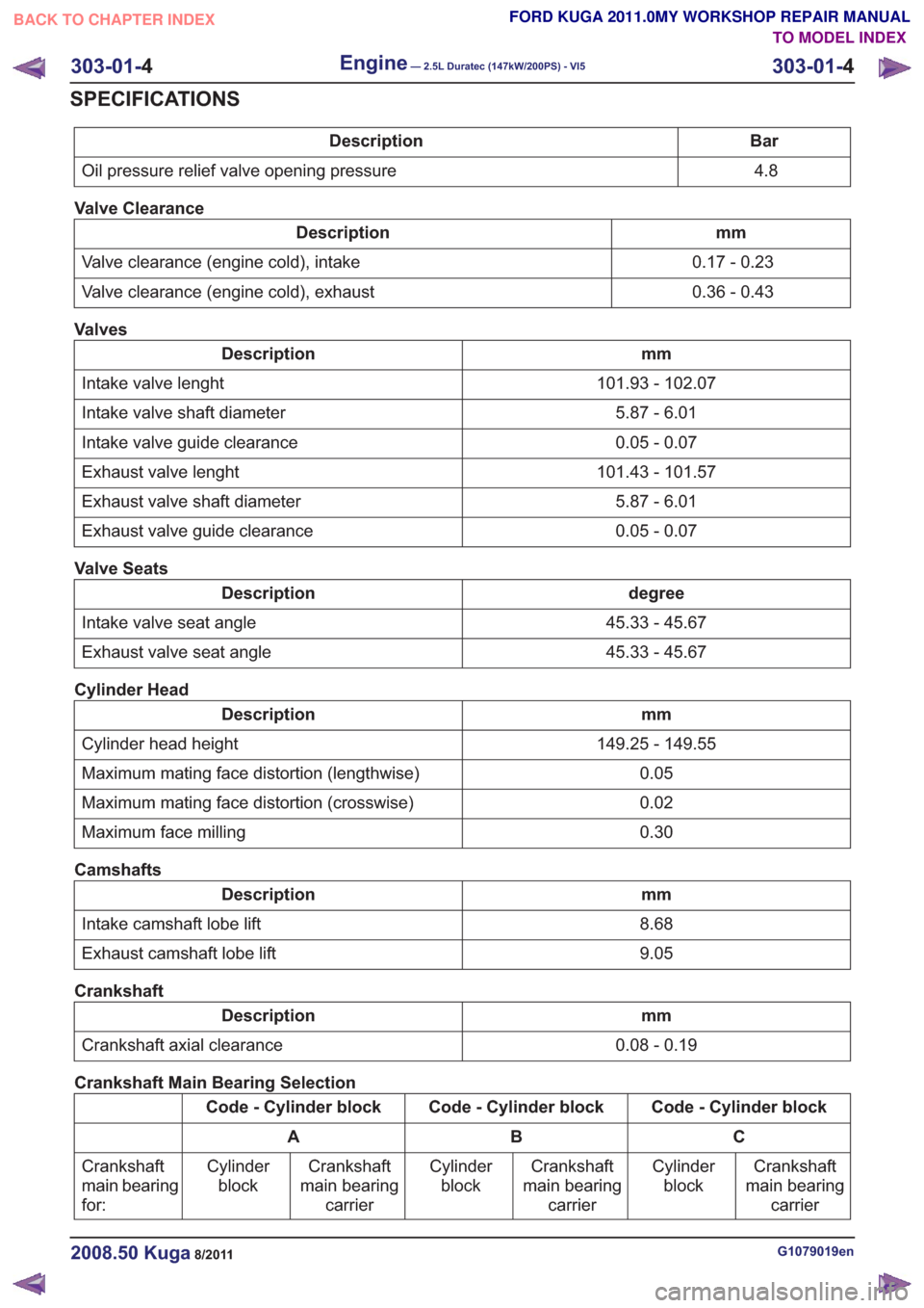
Bar
Description
4.8
Oil pressure relief valve opening pressure
Valve Clearance
mm
Description
0.17 - 0.23
Valve clearance (engine cold), intake
0.36 - 0.43
Valve clearance (engine cold), exhaust
Valves
mm
Description
101.93 - 102.07
Intake valve lenght
5.87 - 6.01
Intake valve shaft diameter
0.05 - 0.07
Intake valve guide clearance
101.43 - 101.57
Exhaust valve lenght
5.87 - 6.01
Exhaust valve shaft diameter
0.05 - 0.07
Exhaust valve guide clearance
Valve Seats
degree
Description
45.33 - 45.67
Intake valve seat angle
45.33 - 45.67
Exhaust valve seat angle
Cylinder Head
mm
Description
149.25 - 149.55
Cylinder head height
0.05
Maximum mating face distortion (lengthwise)
0.02
Maximum mating face distortion (crosswise)
0.30
Maximum face milling
Camshafts
mm
Description
8.68
Intake camshaft lobe lift
9.05
Exhaust camshaft lobe lift
Crankshaft
mm
Description
0.08 - 0.19
Crankshaft axial clearance
Crankshaft Main Bearing Selection
Code - Cylinder block
Code - Cylinder block
Code - Cylinder block
C
B
A
Crankshaft
main bearing carrier
Cylinder
block
Crankshaft
main bearing carrier
Cylinder
block
Crankshaft
main bearing carrier
Cylinder
block
Crankshaft
main bearing
for:
G1079019en2008.50 Kuga8/2011
303-01-
4
Engine— 2.5L Duratec (147kW/200PS) - VI5303-01-
4
SPECIFICATIONS
TO MODEL INDEX
BACK TO CHAPTER INDEX
FORD KUGA 2011.0MY WORKSHOP REPAIR MANUAL