2011 FORD KUGA Oil specification
[x] Cancel search: Oil specificationPage 1964 of 2057
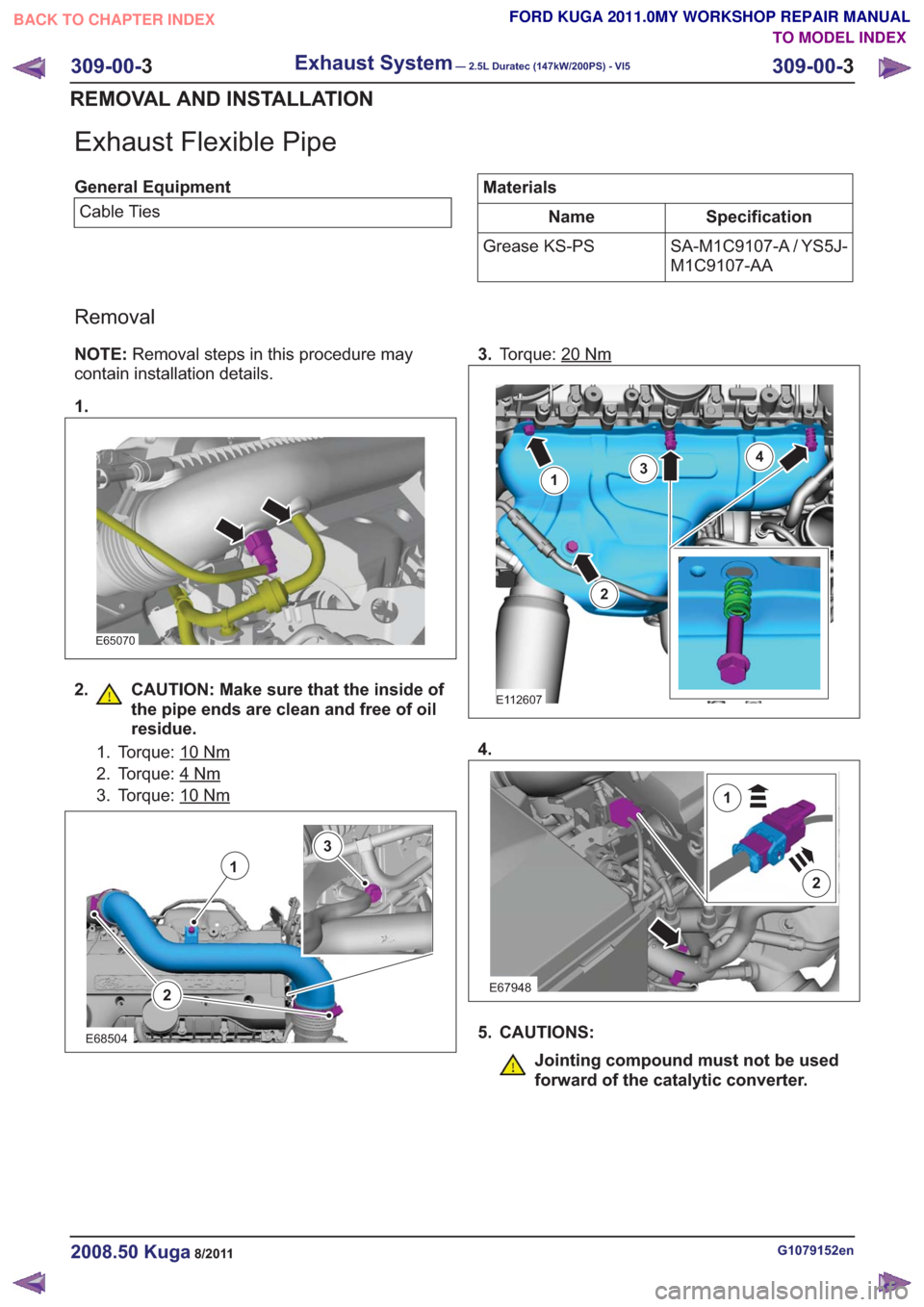
Exhaust Flexible Pipe
General EquipmentCable TiesMaterials
Specification
Name
SA-M1C9107-A / YS5J-
M1C9107-AA
Grease KS-PS
Removal
NOTE:
Removal steps in this procedure may
contain installation details.
1.
E65070
2. CAUTION: Make sure that the inside of the pipe ends are clean and free of oil
residue.
1. Torque: 10Nm
2. Torque: 4Nm
3. Torque: 10Nm
2
1
3
E68504
3.Torque: 20Nm
E112607
1
2
34
4.
E67948
2
1
5. CAUTIONS:
Jointing compound must not be used
forward of the catalytic converter.
G1079152en2008.50 Kuga8/2011
309-00- 3
Exhaust System— 2.5L Duratec (147kW/200PS) - VI5309-00-
3
REMOVAL AND INSTALLATION
TO MODEL INDEX
BACK TO CHAPTER INDEX
FORD KUGA 2011.0MY WORKSHOP REPAIR MANUAL
Page 1971 of 2057
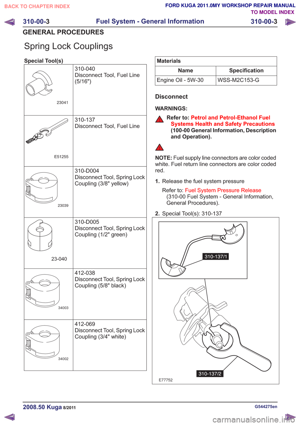
Spring Lock Couplings
Special Tool(s)310-040
Disconnect Tool, Fuel Line
(5/16")
23041
310-137
Disconnect Tool, Fuel Line
E51255
310-D004
Disconnect Tool, Spring Lock
Coupling (3/8" yellow)
23039
310-D005
Disconnect Tool, Spring Lock
Coupling (1/2" green)
23-040
412-038
Disconnect Tool, Spring Lock
Coupling (5/8" black)
34003
412-069
Disconnect Tool, Spring Lock
Coupling (3/4" white)
34002
Materials
Specification
Name
WSS-M2C153-G
Engine Oil - 5W-30
Disconnect
WARNINGS:
Refer to: Petrol and Petrol-Ethanol Fuel
Systems Health and Safety Precautions
(100-00 General Information, Description
and Operation).
NOTE: Fuel supply line connectors are color coded
white. Fuel return line connectors are color coded
red.
1. Release the fuel system pressure
Refer to: Fuel System Pressure Release
(310-00 Fuel System - General Information,
General Procedures).
2. Special Tool(s): 310-137
E77752
G544275en2008.50 Kuga8/2011
310-00- 3
Fuel System - General Information
310-00- 3
GENERAL PROCEDURES
TO MODEL INDEX
BACK TO CHAPTER INDEX
FORD KUGA 2011.0MY WORKSHOP REPAIR MANUAL
Page 2012 of 2057
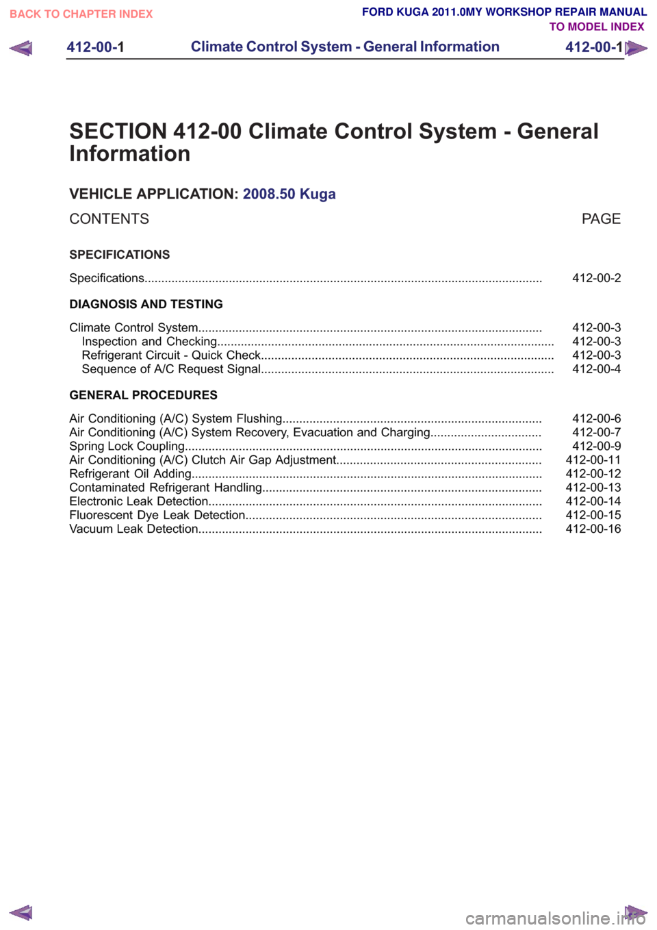
SECTION 412-00 Climate Control System - General
Information
VEHICLE APPLICATION:2008.50 Kuga
PA G E
CONTENTS
SPECIFICATIONS
412-00-2
Specifications ........................................................................\
..............................................
DIAGNOSIS AND TESTING 412-00-3
Climate Control System ........................................................................\
..............................
412-00-3
Inspection and Checking ........................................................................\
............................
412-00-3
Refrigerant Circuit - Quick Check ........................................................................\
...............
412-00-4
Sequence of A/C Request Signal ........................................................................\
...............
GENERAL PROCEDURES 412-00-6
Air Conditioning (A/C) System Flushing ........................................................................\
.....
412-00-7
Air Conditioning (A/C) System Recovery, Evacuation and Charging .................................
412-00-9
Spring Lock Coupling ........................................................................\
..................................
412-00-11
Air Conditioning (A/C) Clutch Air Gap Adjustment .............................................................
412-00-12
Refrigerant Oil Adding ........................................................................\
................................
412-00-13
Contaminated Refrigerant Handling ........................................................................\
...........
412-00-14
Electronic Leak Detection ........................................................................\
...........................
412-00-15
Fluorescent Dye Leak Detection ........................................................................\
................
412-00-16
Vacuum Leak Detection ........................................................................\
..............................
412-00-1
Climate Control System - General Information
412-00- 1
.
TO MODEL INDEX
BACK TO CHAPTER INDEX
FORD KUGA 2011.0MY WORKSHOP REPAIR MANUAL
Page 2013 of 2057
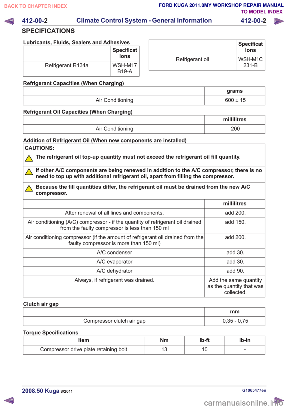
Lubricants, Fluids, Sealers and Adhesives
Specifications
WSH-M17 B19-A
Refrigerant R134a
Specificat
ions
WSH-M1C 231-B
Refrigerant oil
Refrigerant Capacities (When Charging)
grams
600 ± 15
Air Conditioning
Refrigerant Oil Capacities (When Charging)
millilitres 200
Air Conditioning
Addition of Refrigerant Oil (When new components are installed)
CAUTIONS:
The refrigerant oil top-up quantity must not exceed the refrigerant oil fill quantity.
If other A/C components are being renewed in addition to the A/C compressor, there is no
need to top up with additional refrigerant oil, apart from filling the compressor.
Because the fill quantities differ, the refrigerant oil must be drained from the new A/C
compressor.
millilitres add 200.
After renewal of all lines and components.
add 150.
Air conditioning (A/C) compressor - if the quantity of refrigerant oil drained
from the faulty compressor is less than 150 ml
add 200.
Air conditioning compressor (if the amount of refrigerant oil drained from the
faulty compressor is more than 150 ml)
add 30.
A/C condenser
add 30.
A/C evaporator
add 90.
A/C dehydrator
Add the same quantity
as the quantity that was collected.
Always, if refrigerant was drained.
Clutch air gap
mm
0,35 - 0,75
Compressor clutch air gap
Torque Specifications
lb-in
lb-ft
Nm
Item
-
10
13
Compressor drive plate retaining bolt
G1065477en2008.50 Kuga8/2011
412-00- 2
Climate Control System - General Information
412-00- 2
SPECIFICATIONS
TO MODEL INDEX
BACK TO CHAPTER INDEX
FORD KUGA 2011.0MY WORKSHOP REPAIR MANUAL
Page 2018 of 2057
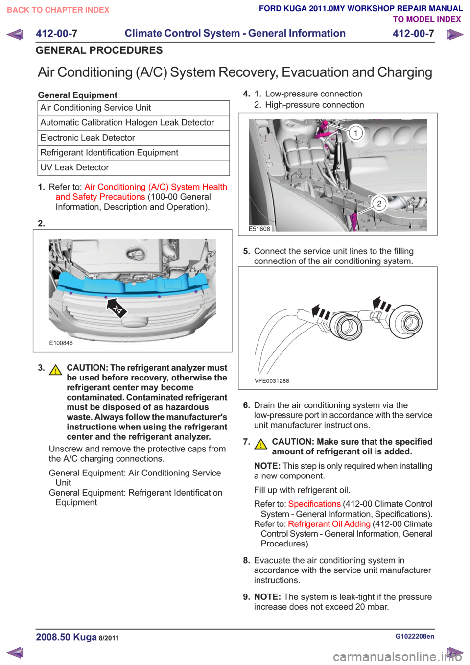
Air Conditioning (A/C) System Recovery, Evacuation and Charging
General EquipmentAir Conditioning Service Unit
Automatic Calibration Halogen Leak Detector
Electronic Leak Detector
Refrigerant Identification Equipment
UV Leak Detector
1. Refer to: Air Conditioning (A/C) System Health
and Safety Precautions (100-00 General
Information, Description and Operation).
2.
E100846
x4
3. CAUTION: The refrigerant analyzer must be used before recovery, otherwise the
refrigerant center may become
contaminated. Contaminated refrigerant
must be disposed of as hazardous
waste. Always follow the manufacturer's
instructions when using the refrigerant
center and the refrigerant analyzer.
Unscrew and remove the protective caps from
the A/C charging connections.
General Equipment: Air Conditioning Service Unit
General Equipment: Refrigerant Identification Equipment 4.
Low-pressure connection
1.
2. High-pressure connection
2
E51608
1
5. Connect the service unit lines to the filling
connection of the air conditioning system.
VFE0031288
6.Drain the air conditioning system via the
low-pressure port in accordance with the service
unit manufacturer instructions.
7. CAUTION: Make sure that the specified amount of refrigerant oil is added.
NOTE:This step is only required when installing
a new component.
Fill up with refrigerant oil.
Refer to: Specifications (412-00 Climate Control
System - General Information, Specifications).
Refer to: Refrigerant Oil Adding (412-00 Climate
Control System - General Information, General
Procedures).
8. Evacuate the air conditioning system in
accordance with the service unit manufacturer
instructions.
9. NOTE: The system is leak-tight if the pressure
increase does not exceed 20 mbar.
G1022208en2008.50 Kuga8/2011
412-00- 7
Climate Control System - General Information
412-00- 7
GENERAL PROCEDURES
TO MODEL INDEX
BACK TO CHAPTER INDEX
FORD KUGA 2011.0MY WORKSHOP REPAIR MANUAL
Page 2019 of 2057
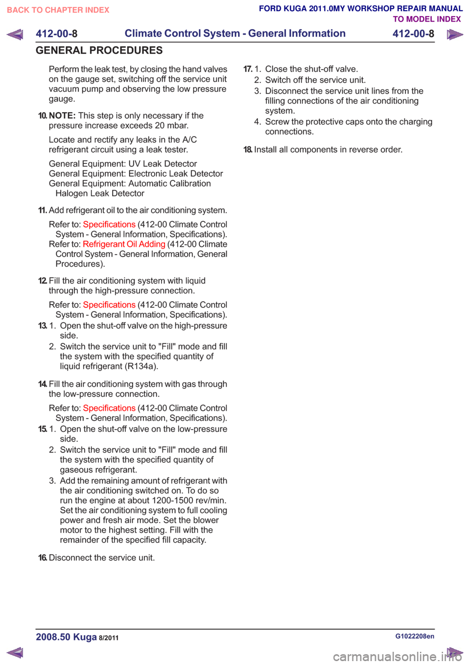
Perform the leak test, by closing the hand valves
on the gauge set, switching off the service unit
vacuum pump and observing the low pressure
gauge.
10. N O T E : This step is only necessary if the
pressure increase exceeds 20 mbar.
Locate and rectify any leaks in the A/C
refrigerant circuit using a leak tester.
General Equipment: UV Leak Detector
General Equipment: Electronic Leak Detector
General Equipment: Automatic Calibration Halogen Leak Detector
11 . Add refrigerant oil to the air conditioning system.
Refer to: Specifications (412-00 Climate Control
System - General Information, Specifications).
Refer to: Refrigerant Oil Adding (412-00 Climate
Control System - General Information, General
Procedures).
12. Fill the air conditioning system with liquid
through the high-pressure connection.
Refer to: Specifications (412-00 Climate Control
System - General Information, Specifications).
13. Open the shut-off valve on the high-pressure
side.
1.
2. Switch the service unit to "Fill" mode and fill
the system with the specified quantity of
liquid refrigerant (R134a).
14. Fill the air conditioning system with gas through
the low-pressure connection.
Refer to: Specifications (412-00 Climate Control
System - General Information, Specifications).
15. Open the shut-off valve on the low-pressure
side.
1.
2. Switch the service unit to "Fill" mode and fill
the system with the specified quantity of
gaseous refrigerant.
3. Add the remaining amount of refrigerant with the air conditioning switched on. To do so
run the engine at about 1200-1500 rev/min.
Set the air conditioning system to full cooling
power and fresh air mode. Set the blower
motor to the highest setting. Fill with the
remainder of the specified fill capacity.
16. Disconnect the service unit. 17.
Close the shut-off valve.
1.
2. Switch off the service unit.
3. Disconnect the service unit lines from the
filling connections of the air conditioning
system.
4. Screw the protective caps onto the charging connections.
18. Install all components in reverse order.
G1022208en2008.50 Kuga8/2011
412-00- 8
Climate Control System - General Information
412-00- 8
GENERAL PROCEDURES
TO MODEL INDEX
BACK TO CHAPTER INDEX
FORD KUGA 2011.0MY WORKSHOP REPAIR MANUAL
Page 2020 of 2057
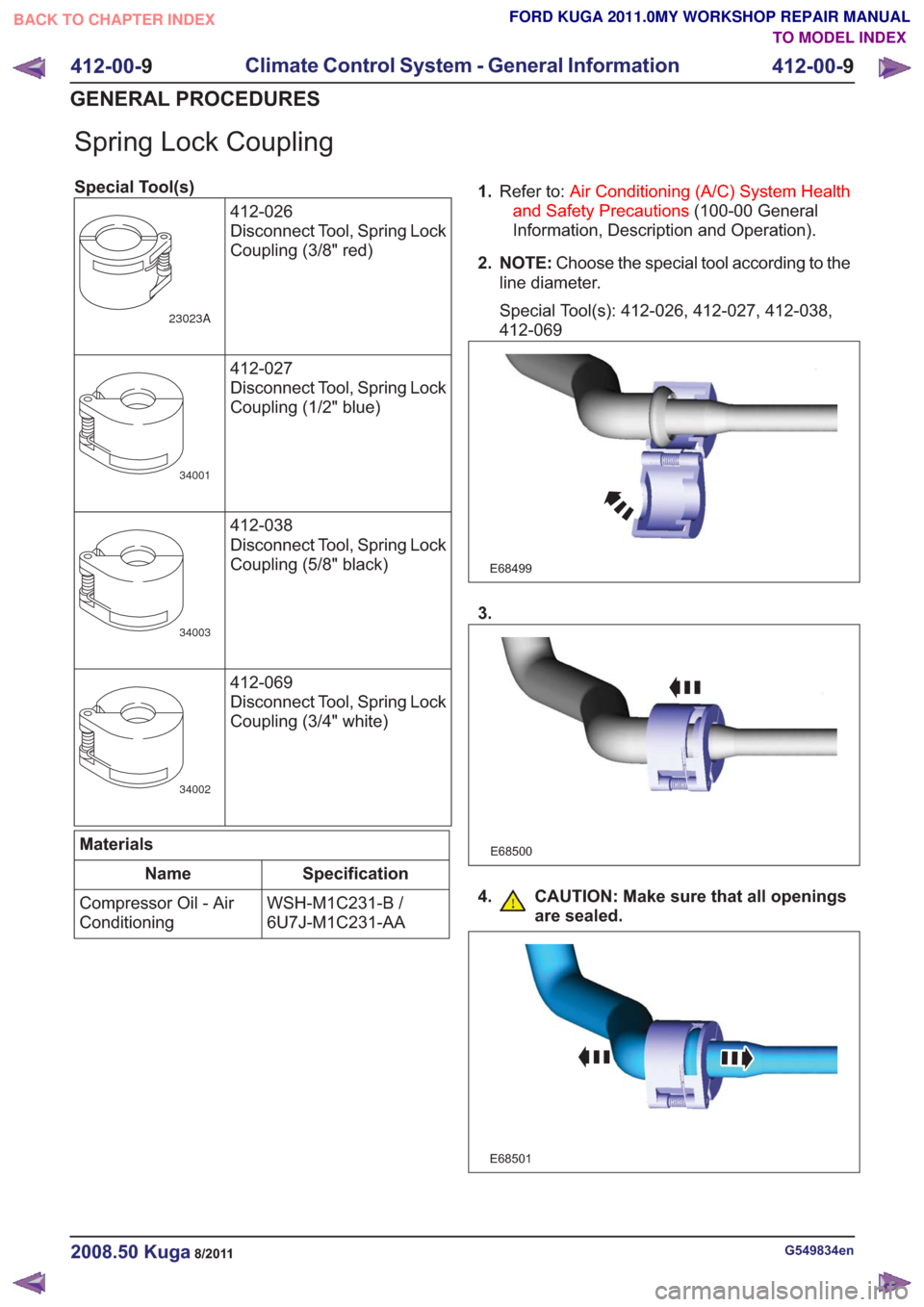
Spring Lock Coupling
Special Tool(s)412-026
Disconnect Tool, Spring Lock
Coupling (3/8" red)
23023A
412-027
Disconnect Tool, Spring Lock
Coupling (1/2" blue)
34001
412-038
Disconnect Tool, Spring Lock
Coupling (5/8" black)
34003
412-069
Disconnect Tool, Spring Lock
Coupling (3/4" white)
34002
Materials
Specification
Name
WSH-M1C231-B /
6U7J-M1C231-AA
Compressor Oil - Air
Conditioning 1.
Refer to: Air Conditioning (A/C) System Health
and Safety Precautions (100-00 General
Information, Description and Operation).
2. NOTE: Choose the special tool according to the
line diameter.
Special Tool(s): 412-026, 412-027, 412-038,
412-069
E68499
3.
E68500
4. CAUTION: Make sure that all openings are sealed.
E68501
G549834en2008.50 Kuga8/2011
412-00- 9
Climate Control System - General Information
412-00- 9
GENERAL PROCEDURES
TO MODEL INDEX
BACK TO CHAPTER INDEX
FORD KUGA 2011.0MY WORKSHOP REPAIR MANUAL
Page 2023 of 2057
Refrigerant Oil Adding
CAUTION: Collect the refrigerant oil in a
clean measuring cylinder.
1. NOTE: This step only needs to be carried out
when removing the A/C compressor.
NOTE: Rotate the compressor shaft at least 6
to 8 turns when draining the refrigerant oil.
Drain the refrigerant oil from the defective A/C
compressor and dispose of it.
2. CAUTIONS:
The refrigerant oil top-up quantity must
not exceed the refrigerant oil fill
quantity.
If other A/C components are being
renewed in addition to the A/C
compressor, there is no need to top up
with additional refrigerant oil, apart from
filling the compressor.
Top up with the calculated quantity of new
refrigerant oil. See:Specifications(412-00
Heating, Ventilation, Air-Conditioning - General
information, Specifications).
G549839en2008.50 Kuga8/2011
412-00- 12
Climate Control System - General Information
412-00- 12
GENERAL PROCEDURES
TO MODEL INDEX
BACK TO CHAPTER INDEX
FORD KUGA 2011.0MY WORKSHOP REPAIR MANUAL