2011 FORD KUGA Heater hose
[x] Cancel search: Heater hosePage 49 of 2057

Solvent-based Adhesives/Sealers - See
Solvents
Follow manufacturers instructions.
Water-based Adhesives/Sealers
Those based on polymer emulsions and rubber
latexes may contain small amounts of volatile toxic
and harmful chemicals. Skin and eye contact
should be avoided and adequate ventilation
provided during use.
Hot Melt Adhesives
In the solid state, they are safe. In the molten state
they may cause burns and health hazards may
arise from the inhalation of toxic fumes.
Use appropriate protective clothing and a
thermostatically controlled heater with a thermal
cut-out and adequate extraction.
Resin-based Adhesives/Sealers, for
example Epoxide and Formaldehyde
Resin-based
Mixing should be carried out in well ventilated
areas, as harmful or toxic volatile chemicals may
be released.
Skin contact with uncured resins and hardeners
can result in irritation, dermatitis, and absorption
of toxic or harmful chemicals through the skin.
Splashes can damage the eyes.
Provide adequate ventilation and avoid skin and
eye contact.
Anaerobic, Cyanoacrylate (super-glues)
and other Acrylic Adhesives
Many are irritant, sensitizing or harmful to the skin
and respiratory tract. Some are eye irritants.
Skin and eye contact should be avoided and the
manufacturers instructions followed.
Cyanoacrylate adhesives (super-glues) MUST NOT
contact the skin or eyes. If skin or eye tissue is
bonded, cover with a clean moist pad and SEEK
IMMEDIATE MEDICAL ATTENTION. Do not
attempt to pull tissue apart. Use in well ventilated
areas as vapors can cause irritation to the nose
and eyes.For two-pack systems see Resin-based and
Isocyanate Adhesives/Sealers.
Isocyanate (Polyurethane)
Adhesives/Sealers
See also
Resin-based Adhesives.
Individuals suffering from asthma or respiratory
allergies should not work with or near these
materials as sensitivity reactions can occur.
Over exposure is irritating to the eyes and
respiratory system. Excessive concentrations may
produce effects on the nervous system including
drowsiness. In extreme cases, loss of
consciousness may result. Long term exposure to
vapor concentrations may result in adverse health
effects.
Prolonged contact with the skin may have a
defatting effect which may lead to skin irritation
and in some cases, dermatitis.
Splashes entering the eye will cause discomfort
and possible damage.
Any spraying should preferably be carried out in
exhaust ventilated booths, removing vapors and
spray droplets from the breathing zone.
Wear appropriate gloves, eye and respiratory
protection.
Antifreeze
See also Fire, Solvents.
For example isopropanol, ethylene glycol,
methanol.
Highly flammable, flammable, combustible.
Used in vehicle coolant systems, brake air pressure
systems, screenwash solutions.
For additional information, refer to: Engine Cooling
System Health and Safety Precautions (100-00
General Information, Description and Operation).
Asbestos
See also Warning Symbols on Vehicles at the end
of this subsection.
Breathing asbestos dust may cause lung damage
or, in some cases, cancer.
Used in brake and clutch linings, transmission
brake bands and gaskets.
G566527en2008.50 Kuga8/2011
100-00- 43
General Information
100-00- 43
DESCRIPTION AND OPERATION
TO MODEL INDEX
BACK TO CHAPTER INDEX
FORD KUGA 2011.0MY WORKSHOP REPAIR MANUAL
Page 54 of 2057

Accidental eye contact should be dealt with as per
normal first aid practices, by flushing the eyes with
an eye wash or clean cool water for 10 minutes,
after which medical attention should be obtained.
Remove and launder clothing which becomes
contaminated with the fluids. Do not place rags
contaminated with fluid in clothing pockets.
Wash thoroughly after completing operations where
skin exposure may have occurred.
It is important that personnel do not smoke, eat or
drink whilst handling the fluids or affected
transmissions. These measures are designed to
limit the risk from accidental ingestion.
Label any decanted fluid properly/use an equivalent
label to that on original product containers.
Clean up any spills promptly using an inert
absorbent and wash down contaminated surfaces
with detergent and water.
Dispose of any waste fluids safely as hazardous
waste.
Safety Data Sheets
Safety Data Sheets, which detail specific material
handling instructions and precautions are available
from the respective national sales company, and
via internet www.msds.ford.com.
Used Engine Oil
Prolonged and repeated contact with mineral oil
will result in the removal of natural fats from the
skin, leading to dryness, irritation and dermatitis.
In addition, used engine oil contains potentially
harmful contaminants, which may cause skin
cancer. Adequate means of skin protection and
washing facilities must be provided.
Do not employ used engine oils as lubricants or
for any application where appreciable skin contact
is likely to occur.
Environmental Precautions
Burning used engine oil in small space heaters or
boilers can be recommended only for units of
approved design. If in doubt check with the
appropriate local authority and manufacturer of
approved appliances.
Dispose of used oil and used oil filters through
authorized waste disposal contractors or licensedwaste disposal sites, or to the waste oil reclamation
trade. If in doubt, contact the relevant local
authority for advice on disposal facilities.
It is illegal to pour used oil on to the ground, down
sewers or drains, or into watercourses.
Noise
Some operations may produce high noise levels,
which could, in time, damage hearing. In these
cases, suitable ear protection must be worn.
Noise Insulation Materials
See
Foams, Fibre Insulation.
O-Rings (Fluoroelastomer)
SeeViton.
Paints
See also Solvents, Chemical Materials.
Highly flammable, flammable - observe No
Smoking policy
One Pack
Can contain harmful or toxic pigments, driers and
other components as well as solvents. Spraying
should be carried out only with adequate
ventilation.
Two Pack
Can also contain harmful and toxic unreacted
resins and resin hardening agents. The
manufacturers instructions should be followed. See
also Resin-based Adhesives and Isocyanate
Adhesives and Sealers under Adhesives and
Sealers.
Spraying should preferably be carried out in
exhausted ventilated booths removing vapor and
spray mists from the breathing zone. Individuals
working in booths should wear appropriate
respiratory protection. Those doing small-scale
repair work in the open workshop should wear
air-fed respirators.
G566527en2008.50 Kuga8/2011
100-00- 49
General Information
100-00- 49
DESCRIPTION AND OPERATION
TO MODEL INDEX
BACK TO CHAPTER INDEX
FORD KUGA 2011.0MY WORKSHOP REPAIR MANUAL
Page 174 of 2057
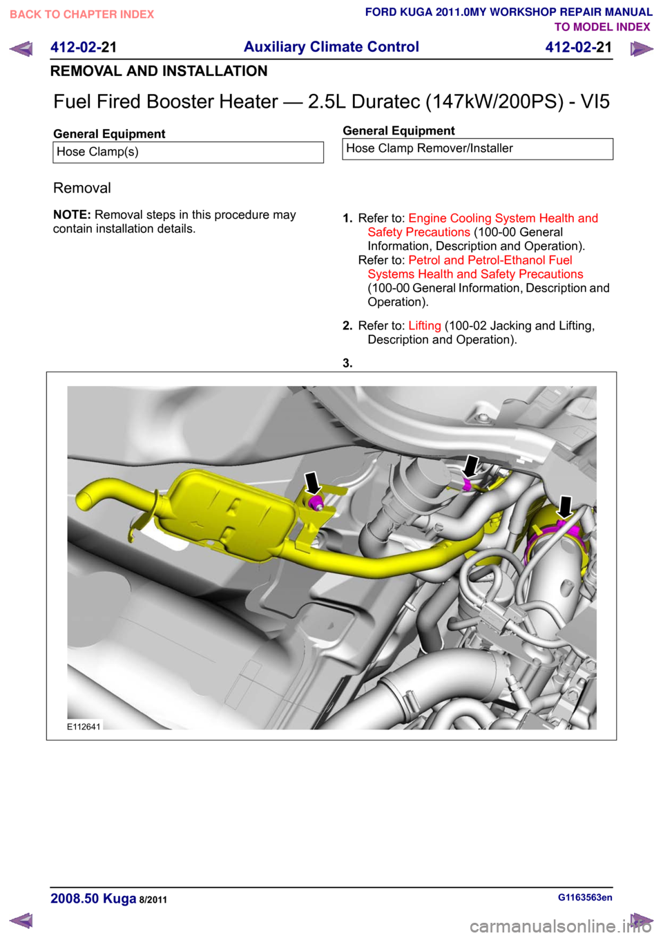
Fuel Fired Booster Heater — 2.5L Duratec (147kW/200PS) - VI5
General Equipment
Hose Clamp(s) General Equipment
Hose Clamp Remover/Installer
Removal
NOTE: Removal steps in this procedure may
contain installation details. 1.
Refer to: Engine Cooling System Health and
Safety Precautions (100-00 General
Information, Description and Operation).
Refer to: Petrol and Petrol-Ethanol Fuel
Systems Health and Safety Precautions
(100-00 General Information, Description and
Operation).
2. Refer to: Lifting(100-02 Jacking and Lifting,
Description and Operation).
3. G1163563en
2008.50 Kuga 8/2011 412-02-21
Auxiliary Climate Control
412-02-21
REMOVAL AND INSTALLATIONTO MODEL INDEX
BACK TO CHAPTER INDEX
FORD KUGA 2011.0MY WORKSHOP REPAIR MANUALE112641
Page 190 of 2057

Instrument Cluster
Refer to
Wiring Diagrams Section 413-01, for
schematic and connector information. General Equipment
The Ford approved diagnostic tool
Inspection and Verification
1. Verify the customer concern.
2. Visually inspect for obvious signs of mechanical
or electrical damage.
Visual Inspection Chart Electrical
Mechanical
– Fuse(s)
– Wiring harness
– Electricalconnector(s)
– Instrument cluster
– Light emitting diode(s) (LED)(s)
– Engine oil filter
– Engine oil level
–
Engine coolant level
– Oil pressure switch
– Engine coolant level
– Coolant thermostat
– Engine coolant temperature (ECT)
sensor
– Fuel gauge
– Collapsed or damaged fuel tank
– Recirculation hose
– Fuel tank filler pipe/hose
– Indicated fuel level
– Fuel lines
– Fuel tank filler cap
– Fuel filter (external to the fuel tank)
– Fuel tank
– Door adjustment
3. If an obvious cause for an observed or reported concern is found, correct the cause (if possible)
before proceeding to the next step.
4. NOTE: If none of the following warning indicators are operating correctly this may
indicate a concern with the central junction
box (CJB). If only one or two of the following
warning indicators are not operating
correctly this may indicate an instrument
cluster concern. Verify the following warning indicators are
working correctly:
• Charging.
• Turn signals.
• Headlamps.
5. If the cause is not visually evident, verify the symptom and refer to the diagnostic tab within
the Ford approved diagnostic tool.
Configuration of the Instrument Cluster
The instrument cluster is a programmable module,
which must be configured by selecting the
Programmable Module Installation Routine on the
Ford approved diagnostic tool.
NOTE: When the new instrument cluster has been
configured with the odometer value, its
configuration cannot be decreased or matched. A
new configuration will result in an increase in the
displayed odometer value by a minimum of two
units.
NOTE: The odometer value must be recorded from
the original instrument cluster before removal.
If the odometer value cannot be obtained from
the original instrument cluster (display failure)
the customer should supply the approximate
value.
The following features will need to be configured
when a new instrument cluster is installed:
• Anti-lock Brake System (ABS)
• All wheel drive
• Keyless vehicle entry
• Electronic power assisted steering
• Trip computer
• Voice control
• Parking aid
• Belt minder
• Safety belt not fastened
• Right hand drive
• Overspeed warning
• Reverse warning
• Turbocharger boost pressure
• Speed control
• Auxiliary heater
• Suspension control
• Washer fluid sensor G1054964en
2008.50 Kuga 8/2011 413-01-7
Instrument Cluster
413-01-7
DIAGNOSIS AND TESTINGTO MODEL INDEX
BACK TO CHAPTER INDEX
FORD KUGA 2011.0MY WORKSHOP REPAIR MANUAL
Page 1675 of 2057
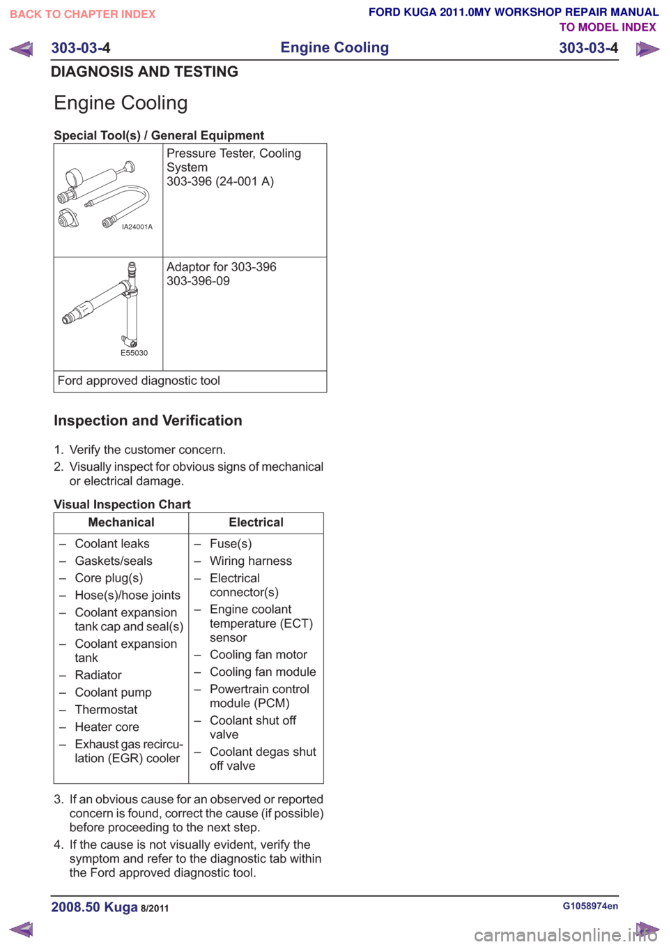
Engine Cooling
Special Tool(s) / General EquipmentPressure Tester, Cooling
System
303-396 (24-001 A)
IA24001A
Adaptor for 303-396
303-396-09
E55030
Ford approved diagnostic tool
Inspection and Verification
1. Verify the customer concern.
2. Visually inspect for obvious signs of mechanicalor electrical damage.
Visual Inspection Chart
Electrical
Mechanical
– Fuse(s)
– Wiring harness
– Electricalconnector(s)
– Engine coolant temperature (ECT)
sensor
– Cooling fan motor
– Cooling fan module
– Powertrain control module (PCM)
– Coolant shut off valve
– Coolant degas shut off valve
– Coolant leaks
– Gaskets/seals
– Core plug(s)
– Hose(s)/hose joints
– Coolant expansion
tank cap and seal(s)
– Coolant expansion tank
– Radiator
– Coolant pump
– Thermostat
– Heater core
– Exhaust gas recircu- lation (EGR) cooler
3. If an obvious cause for an observed or reported concern is found, correct the cause (if possible)
before proceeding to the next step.
4. If the cause is not visually evident, verify the symptom and refer to the diagnostic tab within
the Ford approved diagnostic tool.
G1058974en2008.50 Kuga8/2011
303-03- 4
Engine Cooling
303-03- 4
DIAGNOSIS AND TESTING
TO MODEL INDEX
BACK TO CHAPTER INDEX
FORD KUGA 2011.0MY WORKSHOP REPAIR MANUAL
Page 1982 of 2057
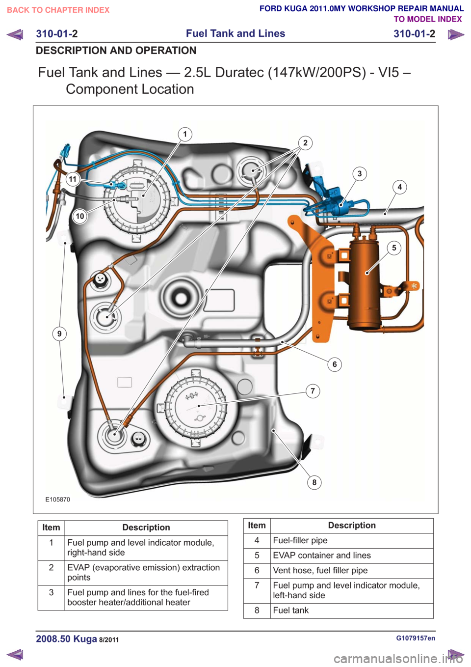
Fuel Tank and Lines — 2.5L Duratec (147kW/200PS) - VI5 –Component Location
E105870
1
2
3
4
5
6
7
8
10
9
11
Description
Item
Fuel pump and level indicator module,
right-hand side
1
EVAP (evaporative emission) extraction
points
2
Fuel pump and lines for the fuel-fired
booster heater/additional heater
3Description
Item
Fuel-filler pipe
4
EVAP container and lines
5
Vent hose, fuel filler pipe
6
Fuel pump and level indicator module,
left-hand side
7
Fuel tank
8
G1079157en2008.50 Kuga8/2011
310-01- 2
Fuel Tank and Lines
310-01- 2
DESCRIPTION AND OPERATION
TO MODEL INDEX
BACK TO CHAPTER INDEX
FORD KUGA 2011.0MY WORKSHOP REPAIR MANUAL
Page 1983 of 2057
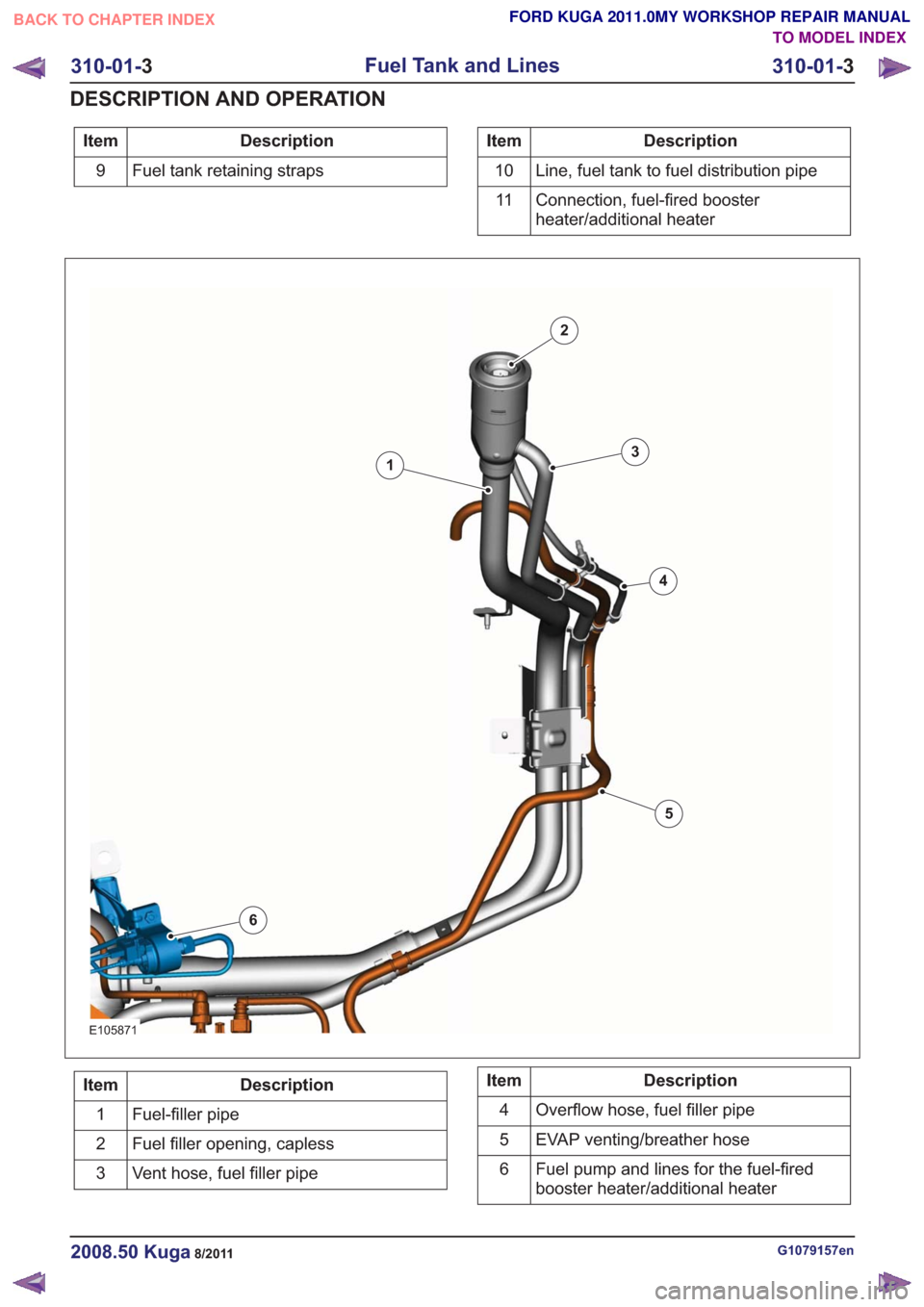
Description
Item
Fuel tank retaining straps
9Description
Item
Line, fuel tank to fuel distribution pipe
10
Connection, fuel-fired booster
heater/additional heater
11
E105871
1
2
3
4
5
6
Description
Item
Fuel-filler pipe
1
Fuel filler opening, capless
2
Vent hose, fuel filler pipe
3Description
Item
Overflow hose, fuel filler pipe
4
EVAP venting/breather hose
5
Fuel pump and lines for the fuel-fired
booster heater/additional heater
6
G1079157en2008.50 Kuga8/2011
310-01-
3
Fuel Tank and Lines
310-01- 3
DESCRIPTION AND OPERATION
TO MODEL INDEX
BACK TO CHAPTER INDEX
FORD KUGA 2011.0MY WORKSHOP REPAIR MANUAL
Page 1986 of 2057
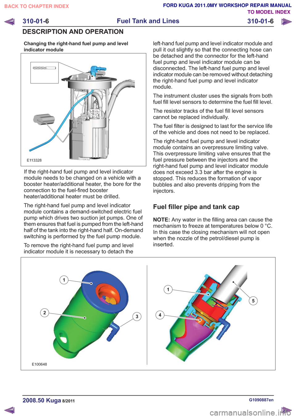
Changing the right-hand fuel pump and level
indicator module
E113328
If the right-hand fuel pump and level indicator
module needs to be changed on a vehicle with a
booster heater/additional heater, the bore for the
connection to the fuel-fired booster
heater/additional heater must be drilled.
The right-hand fuel pump and level indicator
module contains a demand-switched electric fuel
pump which drives two suction jet pumps. One of
them ensures that fuel is pumped from the left-hand
half of the tank into the right-hand half. On-demand
switching is performed by the fuel pump module.
To remove the right-hand fuel pump and level
indicator module it is necessary to detach theleft-hand fuel pump and level indicator module and
pull it out slightly so that the connecting hose can
be detached and the connector for the left-hand
fuel pump and level indicator module can be
disconnected. The left-hand fuel pump and level
indicator module can be removed without detaching
the right-hand fuel pump and level indicator
module.
The instrument cluster uses the signals from both
fuel fill level sensors to determine the fuel fill level.
The resistor tracks of the fuel fill level sensors
cannot be replaced individually.
The fuel filter is designed to last for the service life
of the vehicle and does not need to be replaced.
The right-hand fuel pump and level indicator
module contains an overpressure limiting valve.
This overpressure limiting valve ensures that the
fuel pressure between the injectors and the
right-hand fuel pump and level indicator module
does not exceed 3.3 bar after the engine is
stopped. This reduces the formation of vapor
bubbles and also prevents dripping from the
injectors.
Fuel filler pipe and tank cap
NOTE:
Any water in the filling area can cause the
mechanism to freeze at temperatures below 0 °C.
In this case the closing mechanism will not open
when the nozzle of the petrol/diesel pump is
inserted.
43
1
2
1
5
43
1
2
1
5
E100648
G1090887en2008.50 Kuga8/2011
310-01- 6
Fuel Tank and Lines
310-01- 6
DESCRIPTION AND OPERATION
TO MODEL INDEX
BACK TO CHAPTER INDEX
FORD KUGA 2011.0MY WORKSHOP REPAIR MANUAL