2011 FORD KUGA Ambient temperature sensor
[x] Cancel search: Ambient temperature sensorPage 1797 of 2057
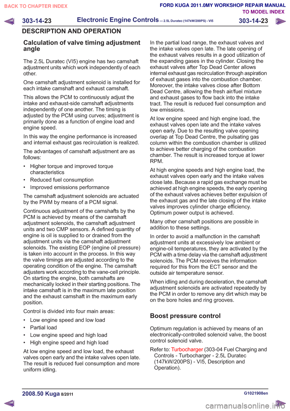
Calculation of valve timing adjustment
angle
The 2.5L Duratec (VI5) engine has two camshaft
adjustment units which work independently of each
other.
One camshaft adjustment solenoid is installed for
each intake camshaft and exhaust camshaft.
This allows the PCM to continuously adjust the
intake and exhaust-side camshaft adjustments
independently of one another. The timing is
adjusted by the PCM using curves; adjustment is
primarily done as a function of engine load and
engine speed.
In this way the engine performance is increased
and internal exhaust gas recirculation is realized.
The advantages of camshaft adjustment are as
follows:
• Higher torque and improved torquecharacteristics
• Reduced fuel consumption
• Improved emissions performance
The camshaft adjustment solenoids are actuated
by the PWM by means of a PCM signal.
Continuous adjustment of the camshafts by the
PCM is achieved by means of the camshaft
adjustment solenoids, the camshaft adjustment
units and two CMP sensors. A defined quantity of
engine is oil is supplied to or drained from the
adjustment units via the camshaft adjustment
solenoids. The existing EOP (engine oil pressure)
is taken into account in the process. In this way
the valve timings are adjusted according to the
operating condition of the engine. The camshaft
adjusters work according to the vane-cell principle.
On starting the engine, both camshafts are
mechanically locked in their starting positions. The
intake camshaft is in the maximum late position
and the exhaust camshaft in the maximum early
position.
Control is divided into four main areas:
• Low engine speed and low load
• Partial load
• Low engine speed and high load
• High engine speed and high load
At low engine speed and low load, the exhaust
valves open early and the intake valves open late.
The result is reduced fuel consumption and more
uniform idling. In the partial load range, the exhaust valves and
the intake valves open late. The late opening of
the exhaust valves results in a good utilization of
the expanding gases in the cylinder. Closing the
exhaust valves after Top Dead Center allows
internal exhaust gas recirculation through aspiration
of exhaust gases into the combustion chamber.
Moreover, the intake valves close after Bottom
Dead Centre, allowing the fresh air/fuel mixture
and exhaust gases to flow back into the intake
tract. The result is reduced fuel consumption and
low emissions.
At low engine speed and high engine load, the
exhaust valves open late and the intake valves
open early. Due to the resulting valve opening
overlap at Top Dead Centre, the pulsating gas
column within the combustion chamber is utilized
to achieve better charging of the combustion
chamber. The result is increased torque at lower
RPM.
At high engine speeds and high engine load, the
exhaust valves open early and the intake valves
close late. Because a rapid gas exchange must be
achieved at high engine speeds, the early opening
of the exhaust valves achieves better expulsion of
the exhaust gas and the late closing of the intake
valves improves cylinder charge efficiency.
Optimum power output is achieved.
Many other camshaft positions are possible in
addition to these settings.
In order to avoid a malfunction in the camshaft
adjustment units at excessively low ambient or
engine-oil temperatures, they are activated by the
PCM with a time delay via the camshaft adjustment
solenoids. The PCM receives the information
required for this from the ECT sensor and the
outside air temperature sensor.
When idling and during deceleration, the camshaft
adjustment solenoids are activated repeatedly by
the PCM in order to remove any dirt which may be
on the bore holes and ring grooves.
Boost pressure control
Optimum regulation is achieved by means of an
electronically-controlled solenoid valve, the boost
control solenoid valve.
Refer to:
Turbocharger (303-04 Fuel Charging and
Controls - Turbocharger - 2.5L Duratec
(147kW/200PS) - VI5, Description and
Operation).
G1021908en2008.50 Kuga8/2011
303-14- 23
Electronic Engine Controls— 2.5L Duratec (147kW/200PS) - VI5303-14-
23
DESCRIPTION AND OPERATION
TO MODEL INDEX
BACK TO CHAPTER INDEX
FORD KUGA 2011.0MY WORKSHOP REPAIR MANUAL
Page 1835 of 2057
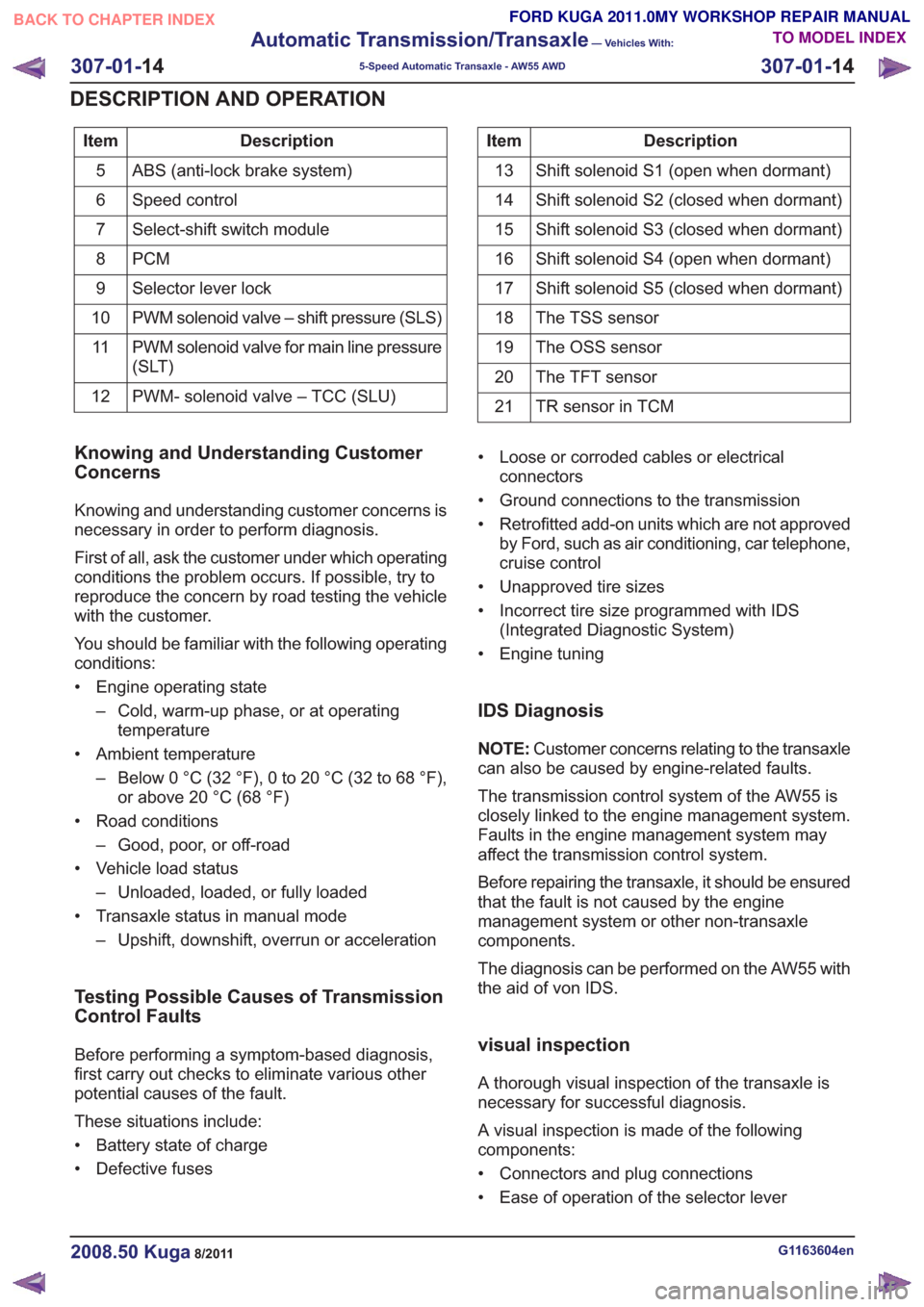
Description
Item
ABS (anti-lock brake system)
5
Speed control
6
Select-shift switch module
7
PCM
8
Selector lever lock
9
PWM solenoid valve – shift pressure (SLS)
10
PWM solenoid valve for main line pressure
(SLT)
11
PWM- solenoid valve – TCC (SLU)
12Description
Item
Shift solenoid S1 (open when dormant)
13
Shift solenoid S2 (closed when dormant)
14
Shift solenoid S3 (closed when dormant)
15
Shift solenoid S4 (open when dormant)
16
Shift solenoid S5 (closed when dormant)
17
The TSS sensor
18
The OSS sensor
19
The TFT sensor
20
TR sensor in TCM
21
Knowing and Understanding Customer
Concerns
Knowing and understanding customer concerns is
necessary in order to perform diagnosis.
First of all, ask the customer under which operating
conditions the problem occurs. If possible, try to
reproduce the concern by road testing the vehicle
with the customer.
You should be familiar with the following operating
conditions:
• Engine operating state
– Cold, warm-up phase, or at operatingtemperature
• Ambient temperature – Below 0 °C (32 °F), 0 to 20 °C (32 to 68 °F),or above 20 °C (68 °F)
• Road conditions – Good, poor, or off-road
• Vehicle load status – Unloaded, loaded, or fully loaded
• Transaxle status in manual mode – Upshift, downshift, overrun or acceleration
Testing Possible Causes of Transmission
Control Faults
Before performing a symptom-based diagnosis,
first carry out checks to eliminate various other
potential causes of the fault.
These situations include:
• Battery state of charge
• Defective fuses • Loose or corroded cables or electrical
connectors
• Ground connections to the transmission
• Retrofitted add-on units which are not approved by Ford, such as air conditioning, car telephone,
cruise control
• Unapproved tire sizes
• Incorrect tire size programmed with IDS (Integrated Diagnostic System)
• Engine tuning
IDS Diagnosis
NOTE: Customer concerns relating to the transaxle
can also be caused by engine-related faults.
The transmission control system of the AW55 is
closely linked to the engine management system.
Faults in the engine management system may
affect the transmission control system.
Before repairing the transaxle, it should be ensured
that the fault is not caused by the engine
management system or other non-transaxle
components.
The diagnosis can be performed on the AW55 with
the aid of von IDS.
visual inspection
A thorough visual inspection of the transaxle is
necessary for successful diagnosis.
A visual inspection is made of the following
components:
• Connectors and plug connections
• Ease of operation of the selector lever
G1163604en2008.50 Kuga8/2011
307-01- 14
Automatic Transmission/Transaxle
— Vehicles With:
5-Speed Automatic Transaxle - AW55 AWD
307-01- 14
DESCRIPTION AND OPERATION
TO MODEL INDEX
BACK TO CHAPTER INDEX
FORD KUGA 2011.0MY WORKSHOP REPAIR MANUAL
Page 1851 of 2057
select-shift switch module transmits a downshift
signal to the TCM.
If you move the gear selector lever backwards (+),
an upshift signal is transmitted to the TCM. In the
instrument cluster, the symbol when the selector
lever is in the 'S' position changes from 'D' to the
current gear, for example 3.
The TCM transmits a signal to the select-shift
switch module to switch on the light emitting diode
for 'S' and to switch off all other light emitting
diodes. The TCM decides whether the shift process
is possible.
If the shift process is permitted, then the various
valves are activated according to the intended
combination for each gear.
In certain situations however, the TCM determines
the gear shifting. The following applies:
• If the vehicle is stationary, only 1st, 2nd and 3rdgears can be selected. 4th gear can be selected
at speeds over 30 km/h and 5th gear at speeds
over 40 km/h.
• The kickdown function is only available in the automatic transmission range 'D'
• Automatic gear changes into the next higher or next lower gear occur at fixed vehicle speeds
and fixed engine speeds
• The permitted engine speed for manual change down agree with that for the kickdown change
up, i.e. an engine speed of approximately 6000
rpm.
• If the temperature inside the transmission rises too high, the TCM takes control of the shift
decisions in order to select a gear in which
activation of torque converter lockup at the
current speed is possible
• Torque converter lockup is possible in 3rd, 4th and 5th gear. (1st and 2nd gears do not have
torque converter lockup)
The signal that specifies the position of the lever
to the select-shift switch module is generated as
follows in the selector lever position 'S': there is a
Hall sensor at the printed circuit board for the
module for each of the three selector lever
positions. A permanent magnet on the cover in the
selector lever affects the output signals to the
control module from the sensors. The control
module recognizes the position of the lever by the
differences in the signal properties.Selector lever from 'N' to 'R' position
The TCM only permits shifting to reverse gear if
the vehicle speed is less than 4.35 mph.
If the vehicle speed is greater than 7 km/h (approx.
4.35 mph), the clutch (C2) and the multi-plate brake
(B3) are not activated and the gearshift is thus
prevented.
Self-test and Diagnosis
The TCM monitors all the transaxle sensors and
electronic components including the PCM. If a fault
occurs, the driver is informed via a warning
indicator and a text message in the instrument
cluster. Faults are stored as DTCs in the fault
memory of the TCM and can be read out and
cleared using the IDS.
Temperature controlled torque converter
lockup
If heavy load and high ambient temperatures cause
an abnormal rise in the transmission temperature,
torque converter lockup is activated as often as
possible (temperature controlled lockup).
This reduces the slip and the heat developed in
the transmission. When the temperature drops
below +20 °C, torque converter lockup is not used.
Slip locking
When changing gear this function makes it possible
for the gears to engage more smoothly with
reduced vibration and less noise. In this mode, the
torque converter clutch is activated but not fully
locked.
The following conditions must be met for the
function to activate:
• Gear selector lever in position D or S.
• Gear 3, 4 or 5.
• The transmission input speed is 1100 rpm or more and the throttle plate opening 20 - 35%.
• The transmission fluid temperature is 40 - 120 °C.
Hill climbing
The TCM can change the shift pattern slightly when
driving uphill to avoid changing gear too often.
G1163605en2008.50 Kuga8/2011
307-01- 30
Automatic Transmission/Transaxle
— Vehicles With:
5-Speed Automatic Transaxle - AW55 AWD
307-01- 30
DESCRIPTION AND OPERATION
TO MODEL INDEX
BACK TO CHAPTER INDEX
FORD KUGA 2011.0MY WORKSHOP REPAIR MANUAL
Page 2028 of 2057
SECTION 412-01 Climate Control
VEHICLE APPLICATION:2008.50 Kuga
PA G E
CONTENTS
SPECIFICATIONS
412-01-3
Specifications ........................................................................\
..............................................
DESCRIPTION AND OPERATION 412-01-4
Climate Control (Component Location) ........................................................................\
......
412-01-10
Climate Control (Overview) ........................................................................\
........................
412-01-10
Pollen filter ........................................................................\
..................................................
412-01-10
Heat exchanger ........................................................................\
..........................................
412-01-10
Evaporator assembly ........................................................................\
..................................
412-01-10
Blower motor ........................................................................\
..............................................
412-01-11
Fault Memory Interrogation without diagnostics unit - vehicles with automatic temperature
control ........................................................................\
.......................................................
412-01-11
Switch over from Celsius to Fahrenheit ........................................................................\
......
412-01-12
Climate Control (System Operation and Component Description) .....................................
412-01-12
System Diagram ........................................................................\
.........................................
412-01-19
System Operation ........................................................................\
.......................................
412-01-19
Climate control housing ........................................................................\
..........................
412-01-22
Climate control ........................................................................\
........................................
412-01-24
Component Description ........................................................................\
..............................
412-01-24
Air conditioning compressor ........................................................................\
...................
412-01-24
Pollen filter ........................................................................\
..............................................
412-01-24
Control assembly, climate control - vehicles with manual temperature control ..............
412-01-25
Control assembly, climate control - vehicles with automatic temperature control ...........
412-01-25
Control assembly, climate control - vehicles with DVD navigation system with a touch
screen........................................................................\
................................................... 412-01-25
Climate control module - vehicles with DVD navigation system with a touch screen.....
412-01-25
Sun sensor - vehicles with automatic temperature control .............................................
412-01-26
In-vehicle temperature sensor ........................................................................\
................
412-01-26
Ambient temperature sensor ........................................................................\
..................
412-01-26
Blower motor ........................................................................\
...........................................
412-01-26
Blower control module - vehicles equipped with automatic temperature control ............
REMOVAL AND INSTALLATION 412-01-28
(34 626 4)
Air Conditioning (A/C) Compressor — 2.5L Duratec (147kW/200PS) - VI5 ....
412-01-29
Air Conditioning (A/C) Compressor to Condenser Discharge Line .....................................
412-01-30
Air Conditioning (A/C) Compressor to Condenser Discharge Line — 2.5L Duratec
(147kW/200PS) - VI5 ........................................................................\
................................
412-01-31
Condenser ........................................................................\
..................................................
412-01-35
Clutch and Clutch Field Coil........................................................................\
.......................
412-01-36
Pollen Filter — RHD........................................................................\
...................................
412-01-37
(34
374 0)
Blower Motor — RHD ........................................................................\
.............
412-01-40
(34 382 0)
Blower Motor Resistor — Vehicles With: Manual Temperature Control, RHD .
412-01-41
(34 382 0)
Blower Motor Resistor — Vehicles With: Dual Automatic Temperature
Control ........................................................................\
..................................
412-01- 1
Climate Control
412-01- 1
.
TO MODEL INDEX
BACK TO CHAPTER INDEX
PAGE 1 OF 2 FORD KUGA 2011.0MY WORKSHOP REPAIR MANUAL
Page 2029 of 2057

412-01-42
Heater Core and Evaporator Core Housing .......................................................................
412-01-45
(34 364 0)
Heater Core — RHD ........................................................................\
...............
412-01-53
Suction Accumulator ........................................................................\
...................................
412-01-56
Suction Accumulator to Air Conditioning (A/C) Compressor Line ......................................
412-01-57
Suction Accumulator to Air Conditioning (A/C) Compressor Line — 2.5L Duratec
(147kW/200PS) - VI5 ........................................................................\
................................
412-01-58
Low-Pressure Cutoff Switch ........................................................................\
.......................
412-01-59
High-Pressure Cutoff Switch ........................................................................\
.......................
412-01-60
Evaporator ........................................................................\
..................................................
412-01-62
Evaporator Outlet Line ........................................................................\
................................
412-01-65
Evaporator Core Orifice ........................................................................\
..............................
412-01-68
Condenser to Evaporator Line........................................................................\
....................
412-01-71
(34 300 0)
Climate Control Assembly — Vehicles With: Manual Temperature Control ....
412-01-72
(34 300 0)
Climate Control Assembly — Vehicles With: Automatic Temperature Control .
412-01-73
(34 485 4)
Footwell Air Discharge Temperature Sensor ..................................................
412-01-74
Center Register Air Discharge Temperature Sensor ..........................................................
412-01-75
In-Vehicle Temperature Sensor ........................................................................\
..................
412-01-76
(34 676 0)
Ambient Air Temperature Sensor ...................................................................
412-01-77
(34 665 0)
Sunload Sensor ........................................................................\
......................
412-01-78
(34 591 0)
Footwell Vent/Duct Blend Door Actuator — RHD ...........................................
412-01-79
(34 606 0)
Air Inlet Blend Door Actuator ........................................................................\
..
412-01-80
(34 608 0)
Driver Side Temperature Blend Door Actuator ...............................................
412-01-81
(34 608 0)
Passenger Side Temperature Blend Door Actuator .......................................
412-01-82
(34 591 0)
Defrost Vent/Register Blend Door Actuator — RHD ......................................
412-01-2
Climate Control
412-01- 2
.
TO MODEL INDEX
BACK TO CHAPTER INDEX
PAGE 2 OF 2 FORD KUGA 2011.0MY WORKSHOP REPAIR MANUAL
Page 2041 of 2057
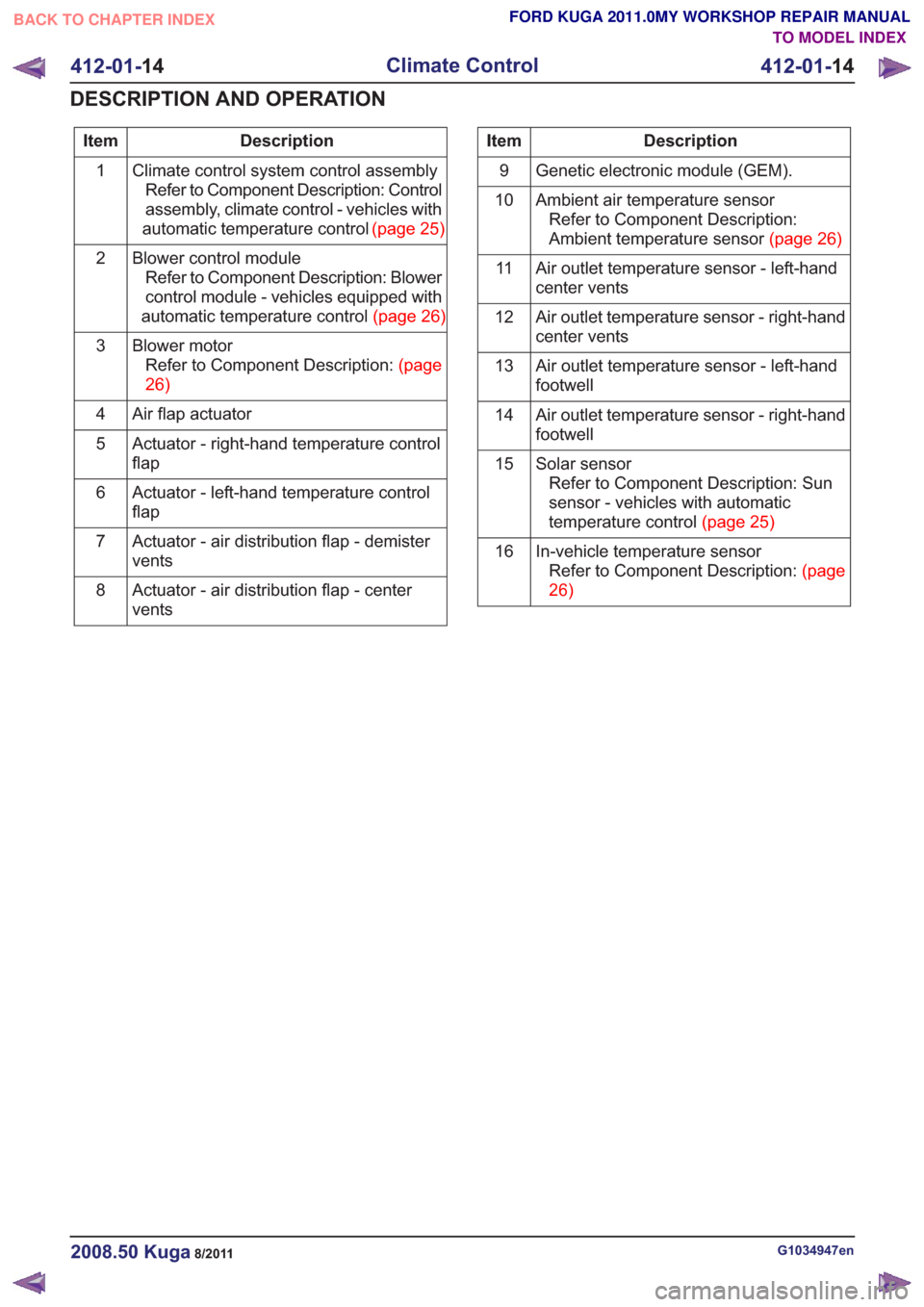
Description
Item
Climate control system control assemblyRefer to Component Description: Control
assembly, climate control - vehicles with
automatictemperaturecontrol (page25)
1
Blower control moduleRefer to Component Description: Blower
control module - vehicles equipped with
automatictemperaturecontrol(page26)
2
Blower motorRefertoComponentDescription:(page
26)
3
Air flap actuator
4
Actuator - right-hand temperature control
flap
5
Actuator - left-hand temperature control
flap
6
Actuator - air distribution flap - demister
vents
7
Actuator - air distribution flap - center
vents
8Description
Item
Genetic electronic module (GEM).
9
Ambient air temperature sensorRefer to Component Description:
Ambienttemperaturesensor(page26)
10
Air outlet temperature sensor - left-hand
center vents
11
Air outlet temperature sensor - right-hand
center vents
12
Air outlet temperature sensor - left-hand
footwell
13
Air outlet temperature sensor - right-hand
footwell
14
Solar sensorRefer to Component Description: Sun
sensor - vehicles with automatic
temperaturecontrol(page25)
15
In-vehicle temperature sensorRefertoComponentDescription:(page
26)
16
G1034947en2008.50 Kuga8/2011
412-01-
14
Climate Control
412-01- 14
DESCRIPTION AND OPERATION
TO MODEL INDEX
BACK TO CHAPTER INDEX
FORD KUGA 2011.0MY WORKSHOP REPAIR MANUAL
Page 2043 of 2057
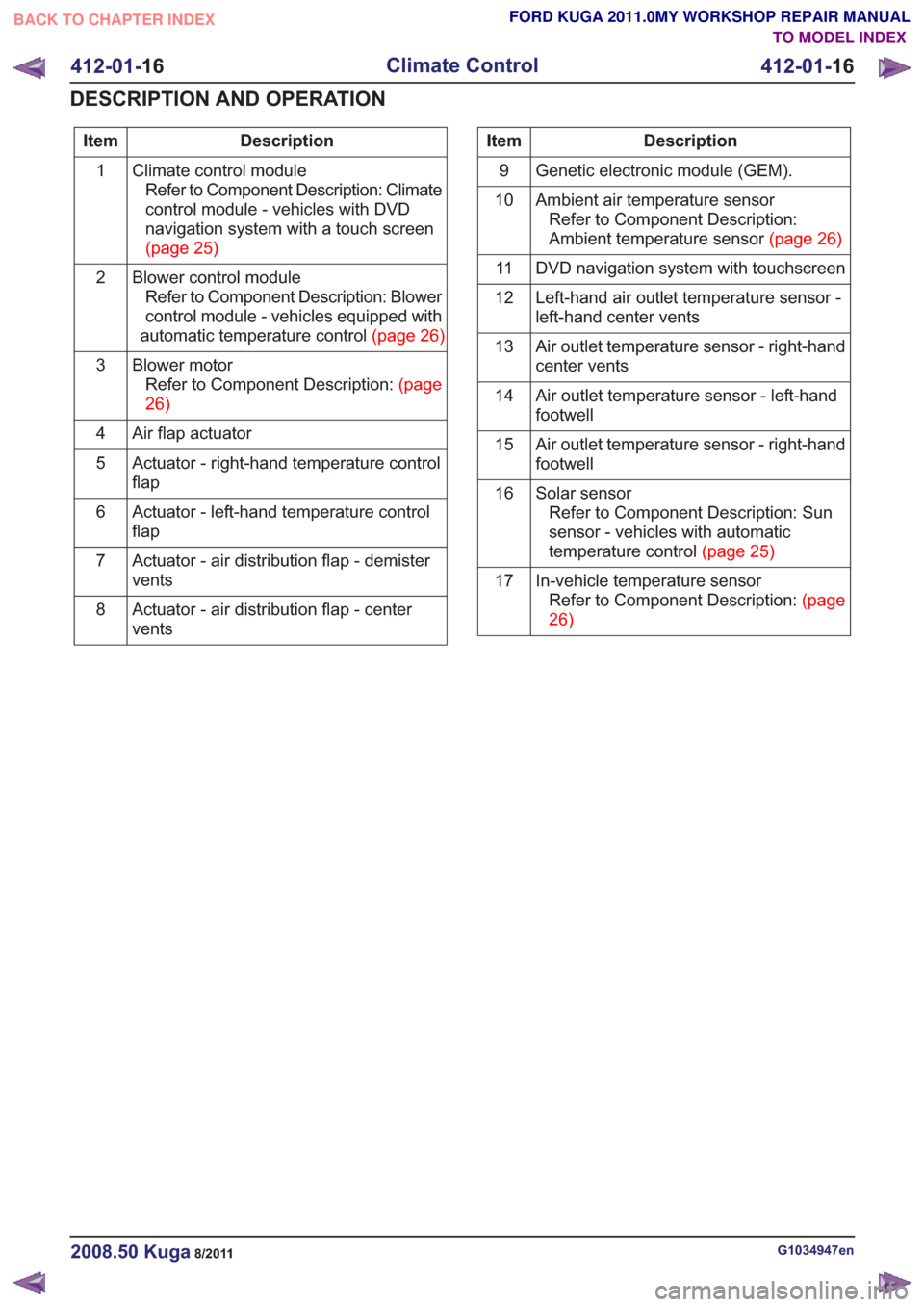
Description
Item
Climate control moduleRefer to Component Description: Climate
control module - vehicles with DVD
navigation system with a touch screen
(page25)
1
Blower control moduleRefer to Component Description: Blower
control module - vehicles equipped with
automatictemperaturecontrol(page26)
2
Blower motorRefertoComponentDescription:(page
26)
3
Air flap actuator
4
Actuator - right-hand temperature control
flap
5
Actuator - left-hand temperature control
flap
6
Actuator - air distribution flap - demister
vents
7
Actuator - air distribution flap - center
vents
8Description
Item
Genetic electronic module (GEM).
9
Ambient air temperature sensorRefer to Component Description:
Ambienttemperaturesensor(page26)
10
DVD navigation system with touchscreen
11
Left-hand air outlet temperature sensor -
left-hand center vents
12
Air outlet temperature sensor - right-hand
center vents
13
Air outlet temperature sensor - left-hand
footwell
14
Air outlet temperature sensor - right-hand
footwell
15
Solar sensorRefer to Component Description: Sun
sensor - vehicles with automatic
temperaturecontrol(page25)
16
In-vehicle temperature sensorRefertoComponentDescription:(page
26)
17
G1034947en2008.50 Kuga8/2011
412-01-
16
Climate Control
412-01- 16
DESCRIPTION AND OPERATION
TO MODEL INDEX
BACK TO CHAPTER INDEX
FORD KUGA 2011.0MY WORKSHOP REPAIR MANUAL
Page 2044 of 2057
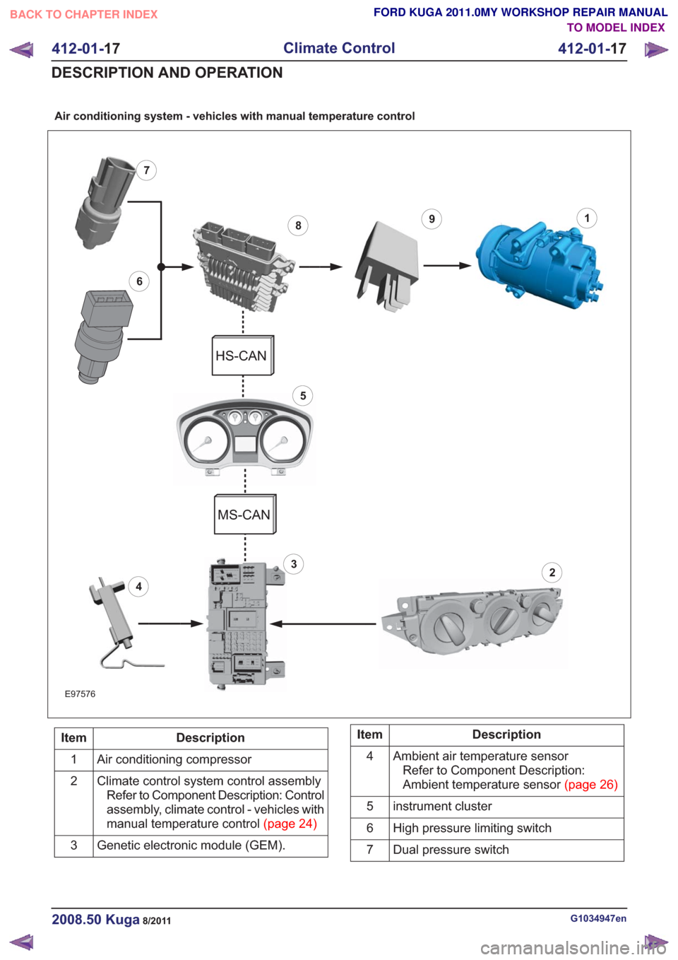
Air conditioning system - vehicles with manual temperature control
18
6
7
3
9
2
5
4
E97576
HS-CAN
MS-CAN
Description
Item
Air conditioning compressor
1
Climate control system control assemblyRefer to Component Description: Control
assembly, climate control - vehicles with
manualtemperaturecontrol(page24)
2
Genetic electronic module (GEM).
3Description
Item
Ambient air temperature sensorRefer to Component Description:
Ambienttemperaturesensor(page26)
4
instrument cluster
5
High pressure limiting switch
6
Dual pressure switch
7
G1034947en2008.50 Kuga8/2011
412-01- 17
Climate Control
412-01- 17
DESCRIPTION AND OPERATION
TO MODEL INDEX
BACK TO CHAPTER INDEX
FORD KUGA 2011.0MY WORKSHOP REPAIR MANUAL