Page 1934 of 2057

External Controls – Overview
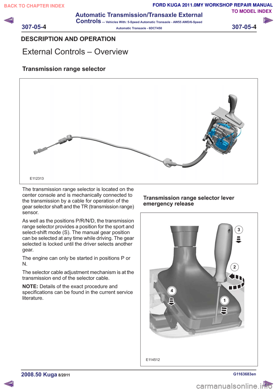
Transmission range selector
E112313
The transmission range selector is located on the
center console and is mechanically connected to
the transmission by a cable for operation of the
gear selector shaft and the TR (transmission range)
sensor.
As well as the positions P/R/N/D, the transmission
range selector provides a position for the sport and
select-shift mode (S). The manual gear position
can be selected at any time while driving. The gear
selected is locked until the driver selects another
gear.
The engine can only be started in positions P or
N.
The selector cable adjustment mechanism is at the
transmission end of the selector cable.
NOTE:Details of the exact procedure and
specifications can be found in the current service
literature.
Transmission range selector lever
emergency release
E114512
1
2
3
4
G1163683en2008.50 Kuga8/2011
DESCRIPTION AND OPERATION
TO MODEL INDEX
BACK TO CHAPTER INDEX
FORD KUGA 2011.0MY WORKSHOP REPAIR MANUAL
307-05-
4
Automatic Transmission/Transaxle External
Controls
— Vehicles With: 5-Speed Automatic Transaxle - AW55 AWD/6-Speed
Automatic Transaxle - 6DCT450
307-05-4
.
Page 1945 of 2057
Transfer Case – Component Location
Powertrain overview
6
6
1
2
3
3
4
5
6
6
E102416
Description
Item
Transaxle with front axle differential
1
Transfer box
2
Front wheel half shafts
3Description
Item
Drive shaft
4
Rear drive axle
5
Rear wheel half shafts
6
G1164985en2008.50 Kuga8/2011
307-07- 3
Transfer Case
— Vehicles With: 5-Speed Automatic Transaxle - AW55
AWD/6-Speed Automatic Transaxle - 6DCT450
307-07- 3
DESCRIPTION AND OPERATION
TO MODEL INDEX
BACK TO CHAPTER INDEX
FORD KUGA 2011.0MY WORKSHOP REPAIR MANUAL
Page 1947 of 2057
Transfer box seals
1
2
3
4
5
E115284
Description
Item
Output drive shaft flange retaining bolt
1
Output drive flange
2Description
Item
Hollow shaft seals, left
3
Hollow shaft seals, right
4
Output differential pinion gear seal
5
G1164985en2008.50 Kuga8/2011
307-07- 5
Transfer Case
— Vehicles With: 5-Speed Automatic Transaxle - AW55
AWD/6-Speed Automatic Transaxle - 6DCT450
307-07- 5
DESCRIPTION AND OPERATION
TO MODEL INDEX
BACK TO CHAPTER INDEX
FORD KUGA 2011.0MY WORKSHOP REPAIR MANUAL
Page 1950 of 2057

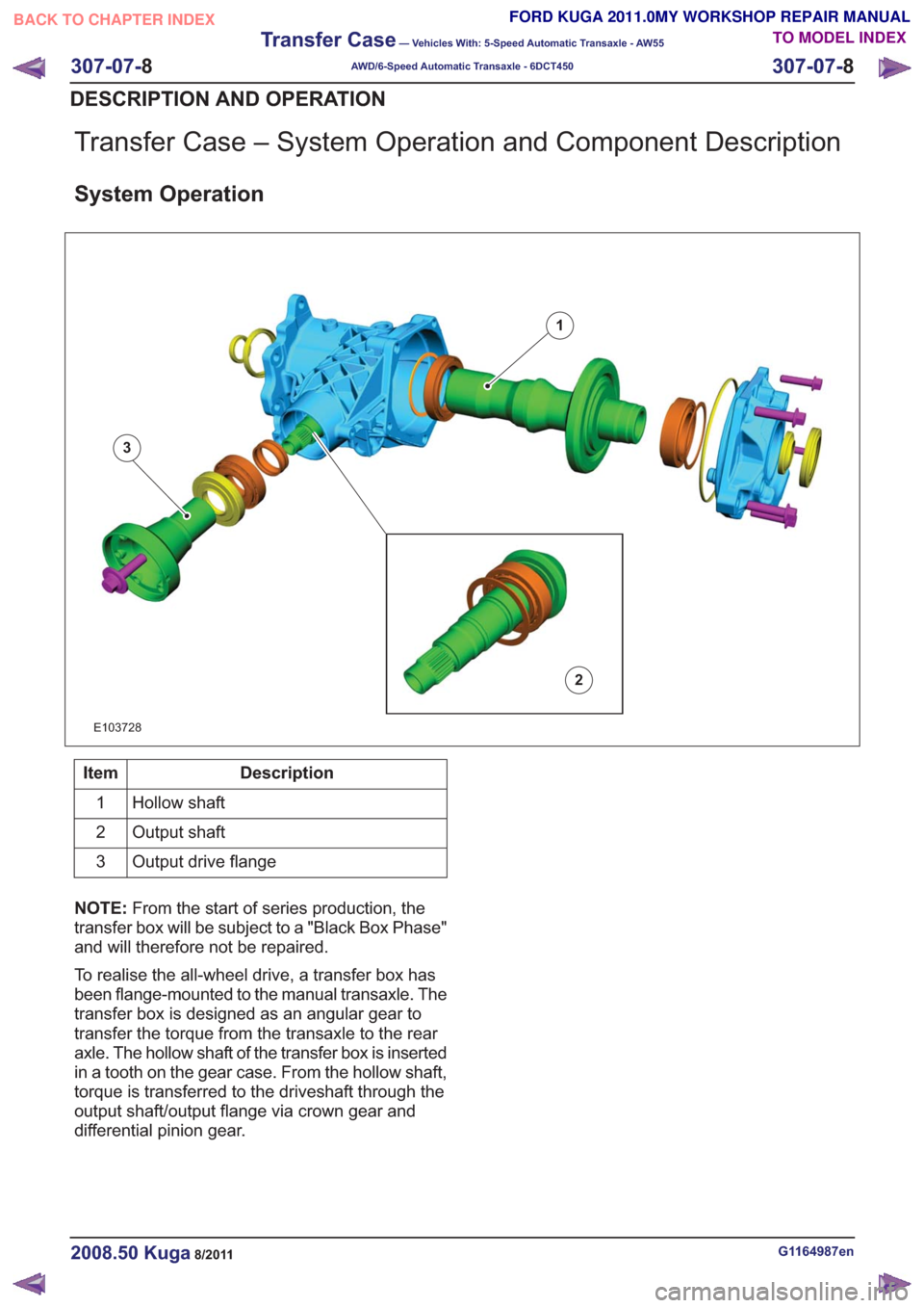
Transfer Case – System Operation and Component Description
System Operation
1
2
3
E103728
Description
Item
Hollow shaft
1
Output shaft
2
Output drive flange
3
NOTE: From the start of series production, the
transfer box will be subject to a "Black Box Phase"
and will therefore not be repaired.
To realise the all-wheel drive, a transfer box has
been flange-mounted to the manual transaxle. The
transfer box is designed as an angular gear to
transfer the torque from the transaxle to the rear
axle. The hollow shaft of the transfer box is inserted
in a tooth on the gear case. From the hollow shaft,
torque is transferred to the driveshaft through the
output shaft/output flange via crown gear and
differential pinion gear.
G1164987en2008.50 Kuga8/2011
307-07- 8
Transfer Case
— Vehicles With: 5-Speed Automatic Transaxle - AW55
AWD/6-Speed Automatic Transaxle - 6DCT450
307-07- 8
DESCRIPTION AND OPERATION
TO MODEL INDEX
BACK TO CHAPTER INDEX
FORD KUGA 2011.0MY WORKSHOP REPAIR MANUAL
Page 1952 of 2057
Transfer Case Connecting Sleeve
Special Tool(s) / General Equipment308-784
Installer, Halfshaft Seal
E115803
Special Tool(s) / General Equipment308-785
Installer, Halfshaft Seal
E115804
Copper Hammer
Flat-bladed screwdriver
Hot Air Gun
Puller
Punch
Removal
G1164990en2008.50 Kuga8/2011
307-07-10
Transfer Case
— Vehicles With: 5-Speed Automatic Transaxle - AW55
AWD/6-Speed Automatic Transaxle - 6DCT450
307-07- 10
REMOVAL AND INSTALLATION
TO MODEL INDEX
BACK TO CHAPTER INDEX
FORD KUGA 2011.0MY WORKSHOP REPAIR MANUAL
Page 1985 of 2057
Fuel Tank and Lines — 2.5L Duratec (147kW/200PS) - VI5 –Overview
Fuel tank
The fuel tank is the same on vehicles with FWD
and AWD. The fuel tank is saddle-shaped to accommodate the drive shaft and the exhaust
system. Depending on the design, the volume of
the tank is 56 liters or 66 liters.
Fuel pump and sender unit
E106247
12
Description
Item
Fuel pump and level indicator module,
left-hand side
Comments:Inactive side without separate fuel pump
1
Fuel pump and level indicator module,
right-hand side
2
G1090887en2008.50 Kuga8/2011
310-01-
5
Fuel Tank and Lines
310-01- 5
DESCRIPTION AND OPERATION
TO MODEL INDEX
BACK TO CHAPTER INDEX
FORD KUGA 2011.0MY WORKSHOP REPAIR MANUAL
Page 1988 of 2057
Fuel Tank — 2.5L Duratec (147kW/200PS) - VI5
Removal
WARNING: Avoid flames, sparks or lighted
substances.
NOTE: Removal steps in this procedure may
contain installation details.
1. Refer to: Battery Disconnect and Connect
(414-01 Battery, Mounting and Cables,
General Procedures).
4x4
2. Refer to: Driveshaft (205-01 Driveshaft,
Removal and Installation).
All vehicles
3. Torque: 48Nm
x2x2
E104225
4.
E104226
5.Torque: 15Nm
E113922
x2
6.Torque: 15Nm
x4x4
E113923
G1175018en2008.50 Kuga8/2011
310-01- 8
Fuel Tank and Lines
310-01- 8
REMOVAL AND INSTALLATION
TO MODEL INDEX
BACK TO CHAPTER INDEX
FORD KUGA 2011.0MY WORKSHOP REPAIR MANUAL