Page 1861 of 2057
E125594
12
4
3
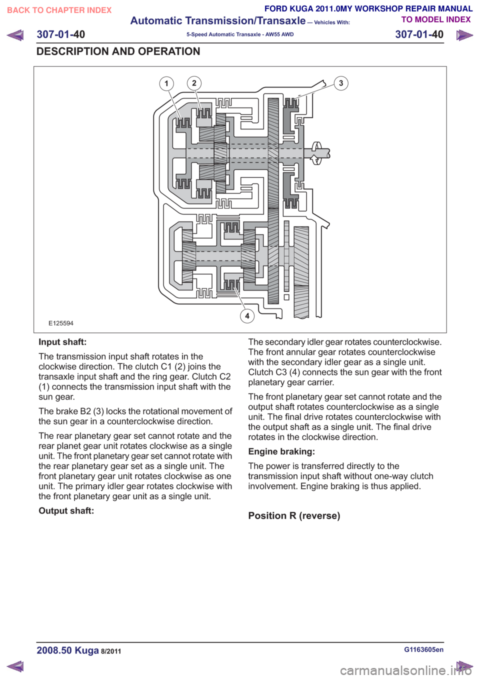
Input shaft:
The transmission input shaft rotates in the
clockwise direction. The clutch C1 (2) joins the
transaxle input shaft and the ring gear. Clutch C2
(1) connects the transmission input shaft with the
sun gear.
The brake B2 (3) locks the rotational movement of
the sun gear in a counterclockwise direction.
The rear planetary gear set cannot rotate and the
rear planet gear unit rotates clockwise as a single
unit. The front planetary gear set cannot rotate with
the rear planetary gear set as a single unit. The
front planetary gear unit rotates clockwise as one
unit. The primary idler gear rotates clockwise with
the front planetary gear unit as a single unit.
Output shaft:The secondary idler gear rotates counterclockwise.
The front annular gear rotates counterclockwise
with the secondary idler gear as a single unit.
Clutch C3 (4) connects the sun gear with the front
planetary gear carrier.
The front planetary gear set cannot rotate and the
output shaft rotates counterclockwise as a single
unit. The final drive rotates counterclockwise with
the output shaft as a single unit. The final drive
rotates in the clockwise direction.
Engine braking:
The power is transferred directly to the
transmission input shaft without one-way clutch
involvement. Engine braking is thus applied.
Position R (reverse)
G1163605en2008.50 Kuga8/2011
307-01-
40
Automatic Transmission/Transaxle
— Vehicles With:
5-Speed Automatic Transaxle - AW55 AWD
307-01- 40
DESCRIPTION AND OPERATION
TO MODEL INDEX
BACK TO CHAPTER INDEX
FORD KUGA 2011.0MY WORKSHOP REPAIR MANUAL
Page 1862 of 2057
E127362
12
3
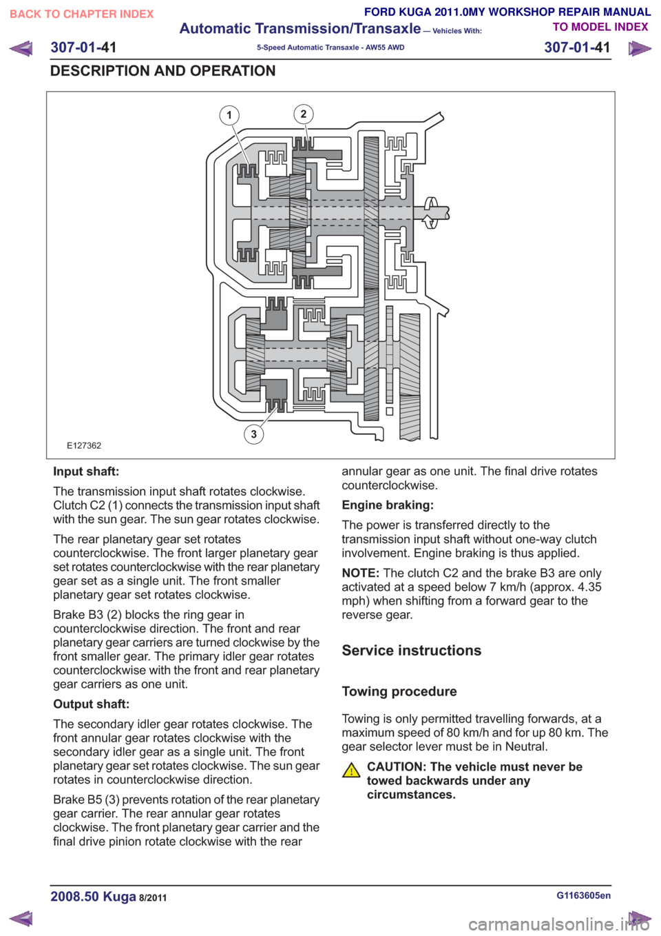
Input shaft:
The transmission input shaft rotates clockwise.
Clutch C2 (1) connects the transmission input shaft
with the sun gear. The sun gear rotates clockwise.
The rear planetary gear set rotates
counterclockwise. The front larger planetary gear
set rotates counterclockwise with the rear planetary
gear set as a single unit. The front smaller
planetary gear set rotates clockwise.
Brake B3 (2) blocks the ring gear in
counterclockwise direction. The front and rear
planetary gear carriers are turned clockwise by the
front smaller gear. The primary idler gear rotates
counterclockwise with the front and rear planetary
gear carriers as one unit.
Output shaft:
The secondary idler gear rotates clockwise. The
front annular gear rotates clockwise with the
secondary idler gear as a single unit. The front
planetary gear set rotates clockwise. The sun gear
rotates in counterclockwise direction.
Brake B5 (3) prevents rotation of the rear planetary
gear carrier. The rear annular gear rotates
clockwise. The front planetary gear carrier and the
final drive pinion rotate clockwise with the rearannular gear as one unit. The final drive rotates
counterclockwise.
Engine braking:
The power is transferred directly to the
transmission input shaft without one-way clutch
involvement. Engine braking is thus applied.
NOTE:
The clutch C2 and the brake B3 are only
activated at a speed below 7 km/h (approx. 4.35
mph) when shifting from a forward gear to the
reverse gear.
Service instructions
Towing procedure
Towing is only permitted travelling forwards, at a
maximum speed of 80 km/h and for up 80 km. The
gear selector lever must be in Neutral.
CAUTION: The vehicle must never be
towed backwards under any
circumstances.
G1163605en2008.50 Kuga8/2011
307-01- 41
Automatic Transmission/Transaxle
— Vehicles With:
5-Speed Automatic Transaxle - AW55 AWD
307-01- 41
DESCRIPTION AND OPERATION
TO MODEL INDEX
BACK TO CHAPTER INDEX
FORD KUGA 2011.0MY WORKSHOP REPAIR MANUAL
Page 1874 of 2057
well as vehicle speed, driving comfort is improved
by linear actuation of the TCC.
Selector lever with integrated select-shift
switch module
E112332
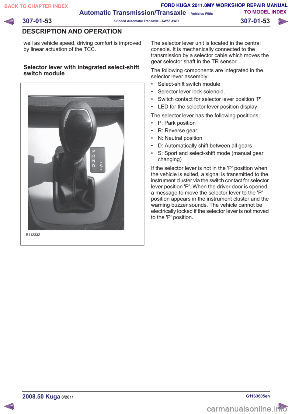
The selector lever unit is located in the central
console. It is mechanically connected to the
transmission by a selector cable which moves the
gear selector shaft in the TR sensor.
The following components are integrated in the
selector lever assembly:
• Select-shift switch module
• Selector lever lock solenoid.
• Switch contact for selector lever position 'P'
• LED for the selector lever position display
The selector lever has the following positions:
• P: Park position
• R: Reverse gear.
• N: Neutral position
• D: Automatically shift between all gears
• S: Sport and select-shift mode (manual gearchanging)
If the selector lever is not in the 'P' position when
the vehicle is exited, a signal is transmitted to the
instrument cluster via the switch contact for selector
lever position 'P'. When the driver door is opened,
a message to move the selector lever to the 'P'
position appears in the instrument cluster and the
warning buzzer sounds. The vehicle cannot be
electrically locked if the selector lever is not moved
to the 'P' position.
G1163605en2008.50 Kuga8/2011
307-01- 53
Automatic Transmission/Transaxle
— Vehicles With:
5-Speed Automatic Transaxle - AW55 AWD
307-01- 53
DESCRIPTION AND OPERATION
TO MODEL INDEX
BACK TO CHAPTER INDEX
FORD KUGA 2011.0MY WORKSHOP REPAIR MANUAL
Page 1876 of 2057
Description
Item
Drive
3
Intake side
4
Delivery side
5
The fluid pump operates on the principle of a
G-rotor fluid pump.
The fluid pump draws transmission fluid from the
fluid pan, builds up fluid pressure and then supplies
it to the valve body.
The fluid pump is driven by the crankshaft via the
torque converter housing.
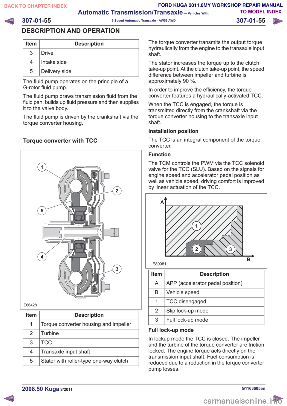
Torque converter with TCC
E66428E66428
1
2
3
5
4
Description
Item
Torque converter housing and impeller
1
Turbine
2
TCC3
Transaxle input shaft
4
Stator with roller-type one-way clutch
5 The torque converter transmits the output torque
hydraulically from the engine to the transaxle input
shaft.
The stator increases the torque up to the clutch
take-up point. At the clutch take-up point, the speed
difference between impeller and turbine is
approximately 90 %.
In order to improve the efficiency, the torque
converter features a hydraulically-activated TCC.
When the TCC is engaged, the torque is
transmitted directly from the crankshaft via the
torque converter housing to the transaxle input
shaft.
Installation position
The TCC is an integral component of the torque
converter.
Function
The TCM controls the PWM via the TCC solenoid
valve for the TCC (SLU). Based on the signals for
engine speed and accelerator pedal position as
well as vehicle speed, driving comfort is improved
by linear actuation of the TCC.
E89081
1
A
B
23
Description
Item
APP (accelerator pedal position)
A
Vehicle speed
B
TCC disengaged
1
Slip lock-up mode
2
Full lock-up mode
3
Full lock-up mode
In lockup mode the TCC is closed. The impeller
and the turbine of the torque converter are friction
locked. The engine torque acts directly on the
transmission input shaft. Fuel consumption is
reduced due to a reduction in the torque converter
pump losses.
G1163605en2008.50 Kuga8/2011
307-01- 55
Automatic Transmission/Transaxle
— Vehicles With:
5-Speed Automatic Transaxle - AW55 AWD
307-01- 55
DESCRIPTION AND OPERATION
TO MODEL INDEX
BACK TO CHAPTER INDEX
FORD KUGA 2011.0MY WORKSHOP REPAIR MANUAL
Page 1888 of 2057
Halfshaft Seal LH
Special Tool(s)303-293
Remover, Crankshaft Seal
21143
Special Tool(s)308-203
Installer, Differential Double
Lip Seal
16066
Removal
1.Refer to: Health and Safety Precautions (100-00
General Information, Description and
Operation).
2. Refer to: Front Halfshaft LH (205-04 Front Drive
Halfshafts, Removal and Installation).
3. Special Tool(s): 303-293
303-293303-293
E114366
Installation
1.Special Tool(s): 308-203
308-203308-203
E114367
2.Refer to: Front Halfshaft LH (205-04 Front Drive
Halfshafts, Removal and Installation).
3. Refer to: Transmission Fluid Level Check
(307-01 Automatic Transmission/Transaxle -
Vehicles With: 5-Speed Automatic Transaxle
- AW55 AWD, General Procedures).
G1163610en2008.50 Kuga8/2011
307-01- 67
Automatic Transmission/Transaxle
— Vehicles With:
5-Speed Automatic Transaxle - AW55 AWD
307-01- 67
REMOVAL AND INSTALLATION
TO MODEL INDEX
BACK TO CHAPTER INDEX
FORD KUGA 2011.0MY WORKSHOP REPAIR MANUAL
Page 1889 of 2057
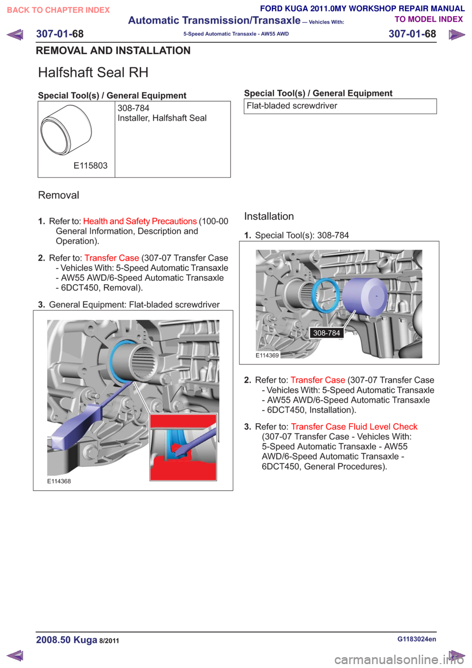
Halfshaft Seal RH
Special Tool(s) / General Equipment308-784
Installer, Halfshaft Seal
E115803
Special Tool(s) / General EquipmentFlat-bladed screwdriver
Removal
1. Refer to: Health and Safety Precautions (100-00
General Information, Description and
Operation).
2. Refer to: Transfer Case (307-07 Transfer Case
- Vehicles With: 5-Speed Automatic Transaxle
- AW55 AWD/6-Speed Automatic Transaxle
- 6DCT450, Removal).
3. General Equipment: Flat-bladed screwdriver
E114368
Installation
1.Special Tool(s): 308-784
308-784308-784
E114369
2.Refer to: Transfer Case (307-07 Transfer Case
- Vehicles With: 5-Speed Automatic Transaxle
- AW55 AWD/6-Speed Automatic Transaxle
- 6DCT450, Installation).
3. Refer to: Transfer Case Fluid Level Check
(307-07 Transfer Case - Vehicles With:
5-Speed Automatic Transaxle - AW55
AWD/6-Speed Automatic Transaxle -
6DCT450, General Procedures).
G1183024en2008.50 Kuga8/2011
307-01- 68
Automatic Transmission/Transaxle
— Vehicles With:
5-Speed Automatic Transaxle - AW55 AWD
307-01- 68
REMOVAL AND INSTALLATION
TO MODEL INDEX
BACK TO CHAPTER INDEX
FORD KUGA 2011.0MY WORKSHOP REPAIR MANUAL
Page 1908 of 2057
25.Refer to: Front Halfshaft LH (205-04 Front Drive
Halfshafts, Removal and Installation).
Refer to: Front Halfshaft RH - LHD 4WD/RHD
4WD (205-04 Front Drive Halfshafts, Removal
and Installation).
26. NOTE: Note the position of the component
before removal.
1.
E101018
27.
E101021
28.
E115557
G1163644en2008.50 Kuga8/2011
307-01-
87
Automatic Transmission/Transaxle
— Vehicles With:
5-Speed Automatic Transaxle - AW55 AWD
307-01- 87
REMOVAL
FORD KUGA 2011.0MY WORKSHOP REPAIR MANUALBACK TO CHAPTER INDEX
TO MODEL INDEX
20 mm
1
2
x3
1
2
x4
3
x2
3
x3
1
2
E101022
29.
x6
x3
Page 1917 of 2057
21.
20 mm1
2
20 mm1
2
E101044
22.Torque: 25Nm
E101021
23. 1. CAUTION: Make sure that the
installation marks are aligned.
Torque: 35Nm
2. Torque: 35Nm
3. Torque: 35Nm
3
x2
2
1
2
1
x3
3
x2
2
1
2
1
x3
E101042
24.Refer to: Front Halfshaft LH (205-04 Front Drive
Halfshafts, Removal and Installation).
25. Torque: 48
Nm1.
2. Torque: 80
Nm
1
2
E114913
G1163646en2008.50 Kuga8/2011
307-01- 96
Automatic Transmission/Transaxle
— Vehicles With:
5-Speed Automatic Transaxle - AW55 AWD
307-01- 96
INSTALLATION
TO MODEL INDEX
BACK TO CHAPTER INDEX
FORD KUGA 2011.0MY WORKSHOP REPAIR MANUAL