Page 1334 of 2057
1
2
E93313
6.On both sides.
Torque: 130
Nm
E101642
7.Remove the following items:
1. Spacer
2. General Equipment: Transmission Jack
8. On both sides.
Torque: 5
Nm
E114252
G1058429en2008.50 Kuga8/2011
205-05- 6
Rear Drive Halfshafts
205-05- 6
REMOVAL AND INSTALLATION
TO MODEL INDEX
BACK TO CHAPTER INDEX
FORD KUGA 2011.0MY WORKSHOP REPAIR MANUAL
Page 1335 of 2057
9.On both sides.
Material: Sealant LGN (WSK-M2G349-A8 /
9U7J-M2G349-AA) adhesive
E120924
10. On both sides.
E101640
11 .On both sides.
Torque: 1
10Nm
x4x4
E101639
12.On both sides.
Refer to: Spring(204-02 Rear Suspension,
Removal and Installation).
13. WARNING: Make sure that no load is placed on the brake hose.
On both sides.
Torque: 1
10Nm
x2x2
E101662
14.On both sides.
Material: Sealant LGN (WSK-M2G349-A8 /
9U7J-M2G349-AA) adhesive
Torque: 50
Nm
E101661
G1058429en2008.50 Kuga8/2011
205-05- 7
Rear Drive Halfshafts
205-05- 7
REMOVAL AND INSTALLATION
TO MODEL INDEX
BACK TO CHAPTER INDEX
FORD KUGA 2011.0MY WORKSHOP REPAIR MANUAL
Page 1336 of 2057
15.On both sides.
Refer to: Wheel and Tire (204-04 Wheels and
Tires, Removal and Installation).
16. Refer to: Differential Fluid Level Check (205-02
Rear Drive Axle/Differential, General
Procedures).
G1058429en2008.50 Kuga8/2011
205-05- 8
Rear Drive Halfshafts
205-05- 8
REMOVAL AND INSTALLATION
TO MODEL INDEX
BACK TO CHAPTER INDEX
FORD KUGA 2011.0MY WORKSHOP REPAIR MANUAL
Page 1423 of 2057
Front wheel sensor
E96823
The ABS sensor rings are built into the seals in the
front wheel bearings. The wheel sensors are joined
to the main wiring harness using a separate
connecting cable.
Rear wheel sensor
E96824
4X4:The ABS sensor rings are pressed onto the
rear drive shafts. The wheel sensors are joined to
the main wiring harness using a separate
connecting cable.
4X2: The ABS sensor rings are built into the hubs
of the rear wheel bearings. When installing a
replacement bearing, ensure that the new part is
aligned correctly. The wheel sensors are joined to
the main wiring harness using a separate
connecting cable.
Opto-electronic steering wheel rotation
sensor
E80158
G1001303en2008.50 Kuga8/2011
206-09B- 5
Anti-Lock Control - Stability Assist
206-09B- 5
DESCRIPTION AND OPERATION
TO MODEL INDEX
BACK TO CHAPTER INDEX
FORD KUGA 2011.0MY WORKSHOP REPAIR MANUAL
Page 1430 of 2057

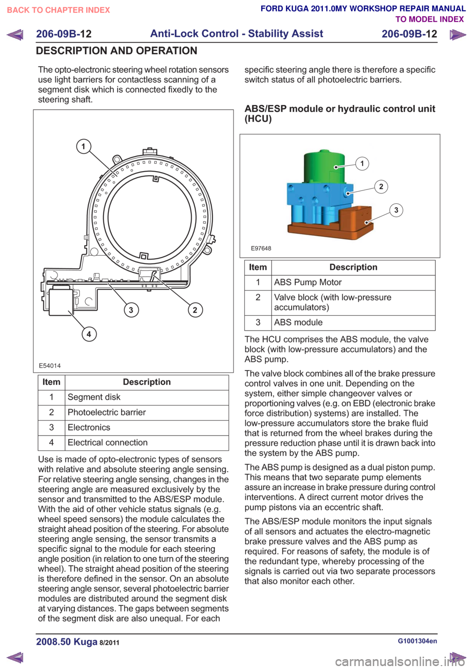
The opto-electronic steering wheel rotation sensors
use light barriers for contactless scanning of a
segment disk which is connected fixedly to the
steering shaft.
E54014
1
23
4
Description
Item
Segment disk
1
Photoelectric barrier
2
Electronics
3
Electrical connection
4
Use is made of opto-electronic types of sensors
with relative and absolute steering angle sensing.
For relative steering angle sensing, changes in the
steering angle are measured exclusively by the
sensor and transmitted to the ABS/ESP module.
With the aid of other vehicle status signals (e.g.
wheel speed sensors) the module calculates the
straight ahead position of the steering. For absolute
steering angle sensing, the sensor transmits a
specific signal to the module for each steering
angle position (in relation to one turn of the steering
wheel). The straight ahead position of the steering
is therefore defined in the sensor. On an absolute
steering angle sensor, several photoelectric barrier
modules are distributed around the segment disk
at varying distances. The gaps between segments
of the segment disk are also unequal. For each specific steering angle there is therefore a specific
switch status of all photoelectric barriers.
ABS/ESP module or hydraulic control unit
(HCU)
E97648
1
2
3
Description
Item
ABS Pump Motor
1
Valve block (with low-pressure
accumulators)
2
ABS module
3
The HCU comprises the ABS module, the valve
block (with low-pressure accumulators) and the
ABS pump.
The valve block combines all of the brake pressure
control valves in one unit. Depending on the
system, either simple changeover valves or
proportioning valves (e.g. on EBD (electronic brake
force distribution) systems) are installed. The
low-pressure accumulators store the brake fluid
that is returned from the wheel brakes during the
pressure reduction phase until it is drawn back into
the system by the ABS pump.
The ABS pump is designed as a dual piston pump.
This means that two separate pump elements
assure an increase in brake pressure during control
interventions. A direct current motor drives the
pump pistons via an eccentric shaft.
The ABS/ESP module monitors the input signals
of all sensors and actuates the electro-magnetic
brake pressure valves and the ABS pump as
required. For reasons of safety, the module is of
the redundant type, whereby processing of the
signals is carried out via two separate processors
that also monitor each other.
G1001304en2008.50 Kuga8/2011
206-09B- 12
Anti-Lock Control - Stability Assist
206-09B- 12
DESCRIPTION AND OPERATION
TO MODEL INDEX
BACK TO CHAPTER INDEX
FORD KUGA 2011.0MY WORKSHOP REPAIR MANUAL
Page 1443 of 2057

Steering System
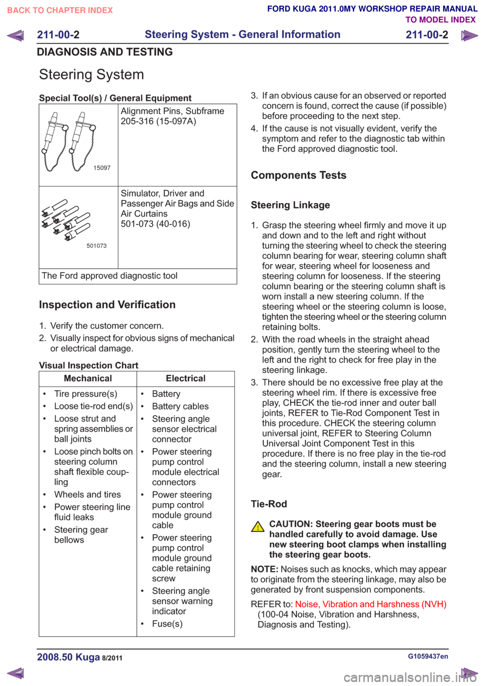
Special Tool(s) / General EquipmentAlignment Pins, Subframe
205-316 (15-097A)
15097
Simulator, Driver and
Passenger Air Bags and Side
Air Curtains
501-073 (40-016)
501073
The Ford approved diagnostic tool
Inspection and Verification
1. Verify the customer concern.
2. Visually inspect for obvious signs of mechanicalor electrical damage.
Visual Inspection Chart
Electrical
Mechanical
• Battery
• Battery cables
• Steering anglesensor electrical
connector
• Power steering pump control
module electrical
connectors
• Power steering pump control
module ground
cable
• Power steering pump control
module ground
cable retaining
screw
• Steering angle sensor warning
indicator
• Fuse(s)
• Tire pressure(s)
• Loose tie-rod end(s)
• Loose strut and
spring assemblies or
ball joints
• Loose pinch bolts on steering column
shaft flexible coup-
ling
• Wheels and tires
• Power steering line fluid leaks
• Steering gear bellows 3. If an obvious cause for an observed or reported
concern is found, correct the cause (if possible)
before proceeding to the next step.
4. If the cause is not visually evident, verify the symptom and refer to the diagnostic tab within
the Ford approved diagnostic tool.
Components Tests
Steering Linkage
1. Grasp the steering wheel firmly and move it upand down and to the left and right without
turning the steering wheel to check the steering
column bearing for wear, steering column shaft
for wear, steering wheel for looseness and
steering column for looseness. If the steering
column bearing or the steering column shaft is
worn install a new steering column. If the
steering wheel or the steering column is loose,
tighten the steering wheel or the steering column
retaining bolts.
2. With the road wheels in the straight ahead position, gently turn the steering wheel to the
left and the right to check for free play in the
steering linkage.
3. There should be no excessive free play at the steering wheel rim. If there is excessive free
play, CHECK the tie-rod inner and outer ball
joints, REFER to Tie-Rod Component Test in
this procedure. CHECK the steering column
universal joint, REFER to Steering Column
Universal Joint Component Test in this
procedure. If there is no free play in the tie-rod
and the steering column, install a new steering
gear.
Tie-Rod
CAUTION: Steering gear boots must be
handled carefully to avoid damage. Use
new steering boot clamps when installing
the steering gear boots.
NOTE: Noises such as knocks, which may appear
to originate from the steering linkage, may also be
generated by front suspension components.
REFER to: Noise, Vibration and Harshness (NVH)
(100-04 Noise, Vibration and Harshness,
Diagnosis and Testing).
G1059437en2008.50 Kuga8/2011
211-00- 2
Steering System - General Information
211-00- 2
DIAGNOSIS AND TESTING
TO MODEL INDEX
BACK TO CHAPTER INDEX
FORD KUGA 2011.0MY WORKSHOP REPAIR MANUAL
Page 1469 of 2057

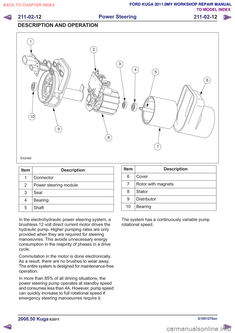
1
2
3
45
6
7
8
9
10
E42460
Description
Item
Connector
1
Power steering module
2
Seal
3
Bearing
4
Shaft
5Description
Item
Cover
6
Rotor with magnets
7
Stator8
Distributor
9
Bearing
10
In the electrohydraulic power steering system, a
brushless 12 volt direct current motor drives the
hydraulic pump. Higher pumping rates are only
provided when they are required for steering
manoeuvres. This avoids unnecessary energy
consumption in the majority of phases in a drive
cycle.
Commutation in the motor is done electronically.
As a result, there are no brushes to wear away.
The entire system is designed for maintenance-free
operation.
In more than 85% of all driving situations, the
power steering pump operates at standby speed
and consumes less than 4A. However, pump speed
can quickly increase to full rotational speed if
emergency steering manoeuvres require it. The system has a continuously variable pump
rotational speed.
G1001270en2008.50 Kuga8/2011
211-02-
12
Power Steering
211-02- 12
DESCRIPTION AND OPERATION
TO MODEL INDEX
BACK TO CHAPTER INDEX
FORD KUGA 2011.0MY WORKSHOP REPAIR MANUAL
Page 1503 of 2057
Steering Column – Overview
General overview
E98628
1
2
3
4
5
6
7
8
9
Description
Item
Driver airbag
Refer to: Air Bag and Safety Belt
Pretensioner Supplemental Restraint
System (SRS) (501-20 Supplemental
Restraint System, Description and
Operation).
1
Steering wheel
2
Switch unit, steering column
Refer to: Steering Column Switches
(211-05 Steering Column Switches,
Description and Operation).
3Description
Item
Steering column lower shroud
4
Steering column upper shroud
5
Steering Column
6
Steering lock
7
Extension, steering shaft
8
Steering gear to bulkhead seal
9
G1030751en2008.50 Kuga8/2011
211-04- 2
Steering Column
211-04- 2
DESCRIPTION AND OPERATION
TO MODEL INDEX
BACK TO CHAPTER INDEX
FORD KUGA 2011.0MY WORKSHOP REPAIR MANUAL