2011 FORD KUGA Drive shaft
[x] Cancel search: Drive shaftPage 1828 of 2057
E125525
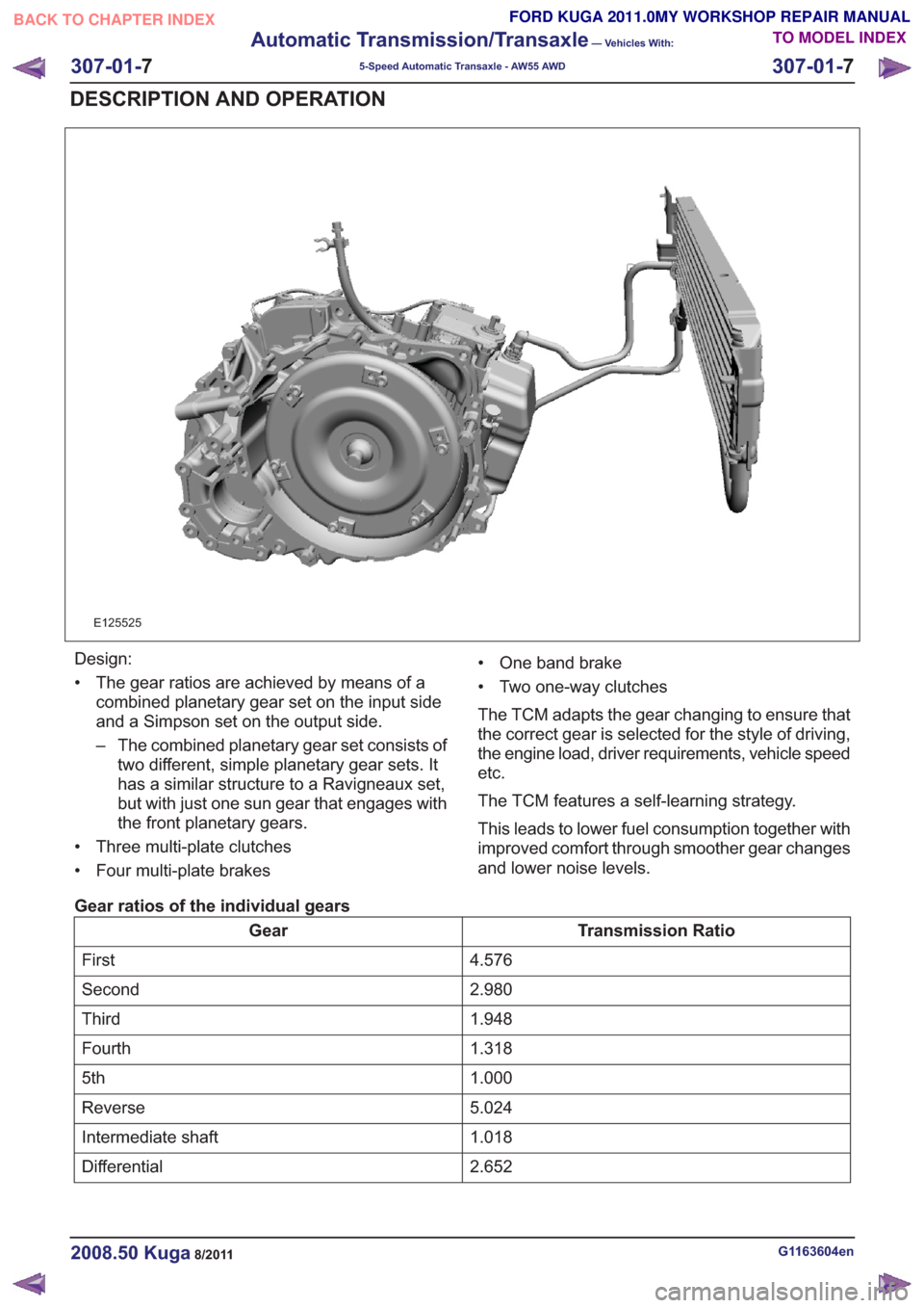
Design:
• The gear ratios are achieved by means of acombined planetary gear set on the input side
and a Simpson set on the output side.
– The combined planetary gear set consists oftwo different, simple planetary gear sets. It
has a similar structure to a Ravigneaux set,
but with just one sun gear that engages with
the front planetary gears.
• Three multi-plate clutches
• Four multi-plate brakes • One band brake
• Two one-way clutches
The TCM adapts the gear changing to ensure that
the correct gear is selected for the style of driving,
the engine load, driver requirements, vehicle speed
etc.
The TCM features a self-learning strategy.
This leads to lower fuel consumption together with
improved comfort through smoother gear changes
and lower noise levels.
Gear ratios of the individual gears
Transmission Ratio
Gear
4.576
First
2.980
Second
1.948
Third
1.318
Fourth
1.000
5th
5.024
Reverse
1.018
Intermediate shaft
2.652
Differential
G1163604en2008.50 Kuga8/2011
307-01- 7
Automatic Transmission/Transaxle
— Vehicles With:
5-Speed Automatic Transaxle - AW55 AWD
307-01- 7
DESCRIPTION AND OPERATION
TO MODEL INDEX
BACK TO CHAPTER INDEX
FORD KUGA 2011.0MY WORKSHOP REPAIR MANUAL
Page 1830 of 2057
1
234
5
6
8
9
7
E112582
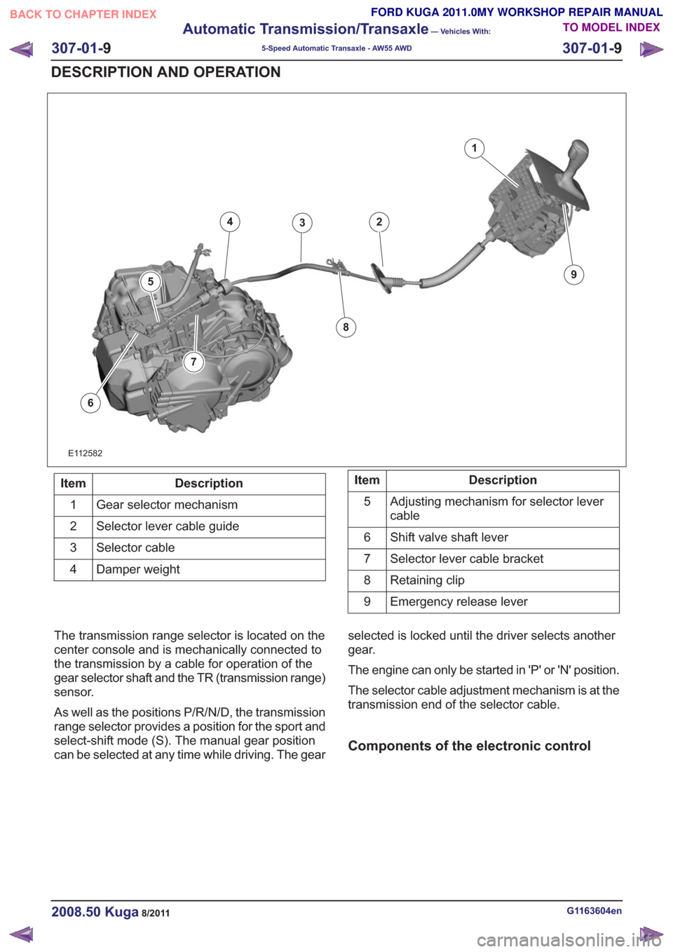
Description
Item
Gear selector mechanism
1
Selector lever cable guide
2
Selector cable
3
Damper weight
4Description
Item
Adjusting mechanism for selector lever
cable
5
Shift valve shaft lever
6
Selector lever cable bracket
7
Retaining clip
8
Emergency release lever
9
The transmission range selector is located on the
center console and is mechanically connected to
the transmission by a cable for operation of the
gear selector shaft and the TR (transmission range)
sensor.
As well as the positions P/R/N/D, the transmission
range selector provides a position for the sport and
select-shift mode (S). The manual gear position
can be selected at any time while driving. The gear selected is locked until the driver selects another
gear.
The engine can only be started in 'P' or 'N' position.
The selector cable adjustment mechanism is at the
transmission end of the selector cable.
Components of the electronic control
G1163604en2008.50 Kuga8/2011
307-01-
9
Automatic Transmission/Transaxle
— Vehicles With:
5-Speed Automatic Transaxle - AW55 AWD
307-01- 9
DESCRIPTION AND OPERATION
TO MODEL INDEX
BACK TO CHAPTER INDEX
FORD KUGA 2011.0MY WORKSHOP REPAIR MANUAL
Page 1842 of 2057
Transmission Description – System Operation and ComponentDescription
System Operation
E112576
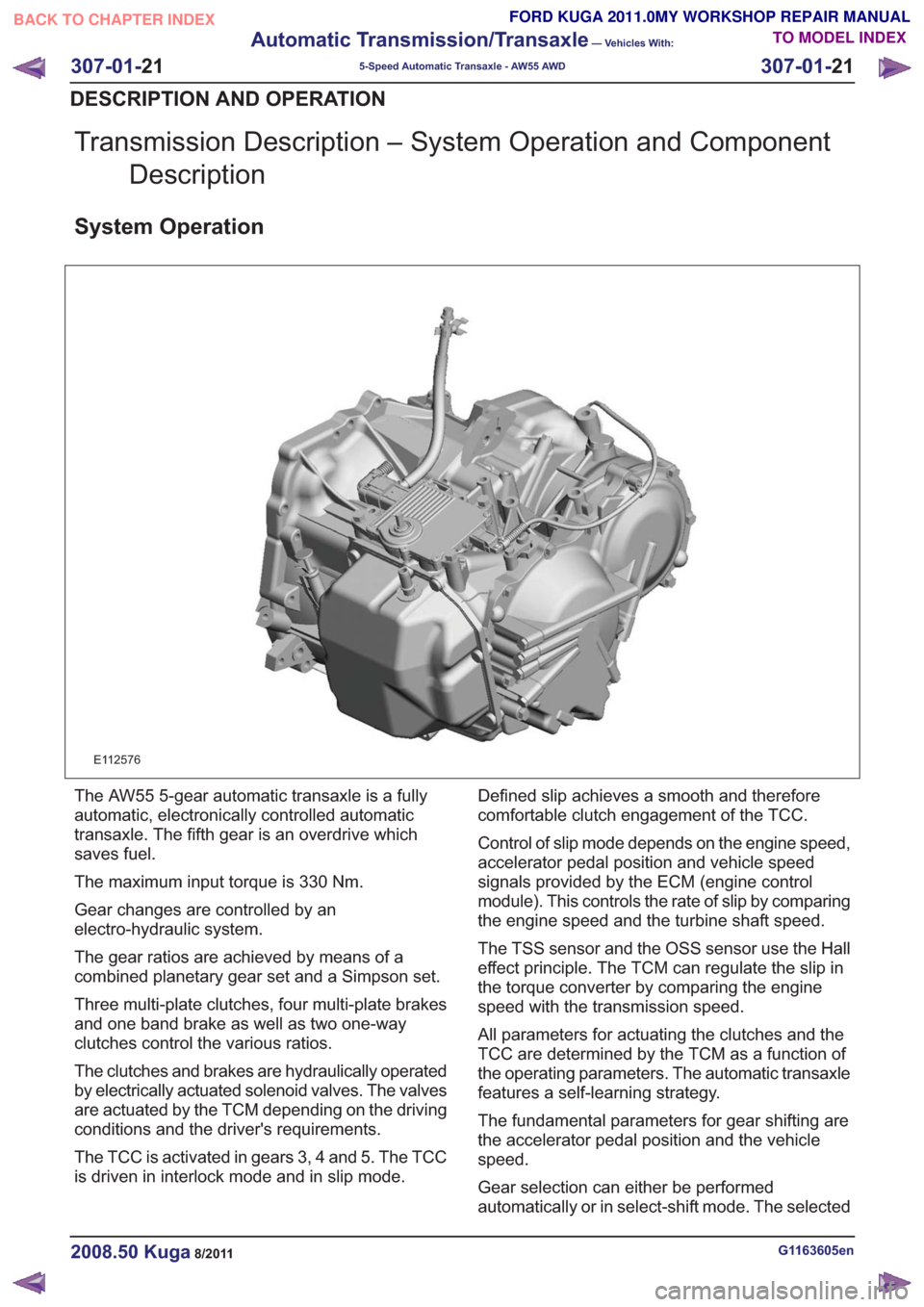
The AW55 5-gear automatic transaxle is a fully
automatic, electronically controlled automatic
transaxle. The fifth gear is an overdrive which
saves fuel.
The maximum input torque is 330 Nm.
Gear changes are controlled by an
electro-hydraulic system.
The gear ratios are achieved by means of a
combined planetary gear set and a Simpson set.
Three multi-plate clutches, four multi-plate brakes
and one band brake as well as two one-way
clutches control the various ratios.
The clutches and brakes are hydraulically operated
by electrically actuated solenoid valves. The valves
are actuated by the TCM depending on the driving
conditions and the driver's requirements.
The TCC is activated in gears 3, 4 and 5. The TCC
is driven in interlock mode and in slip mode. Defined slip achieves a smooth and therefore
comfortable clutch engagement of the TCC.
Control of slip mode depends on the engine speed,
accelerator pedal position and vehicle speed
signals provided by the ECM (engine control
module). This controls the rate of slip by comparing
the engine speed and the turbine shaft speed.
The TSS sensor and the OSS sensor use the Hall
effect principle. The TCM can regulate the slip in
the torque converter by comparing the engine
speed with the transmission speed.
All parameters for actuating the clutches and the
TCC are determined by the TCM as a function of
the operating parameters. The automatic transaxle
features a self-learning strategy.
The fundamental parameters for gear shifting are
the accelerator pedal position and the vehicle
speed.
Gear selection can either be performed
automatically or in select-shift mode. The selected
G1163605en2008.50 Kuga8/2011
307-01-
21
Automatic Transmission/Transaxle
— Vehicles With:
5-Speed Automatic Transaxle - AW55 AWD
307-01- 21
DESCRIPTION AND OPERATION
TO MODEL INDEX
BACK TO CHAPTER INDEX
FORD KUGA 2011.0MY WORKSHOP REPAIR MANUAL
Page 1847 of 2057

E112322
The TCM adapts the gear changing to ensure that
the correct gear is selected for the style of driving,
the engine load, driver requirements, vehicle speed
etc. This leads to lower fuel consumption together
with improved comfort through smoother gear
changes and lower noise levels.
The TCM receives information on the driver's
desired transmission range and type of driving
mode. In contrast to a transmission which is only
controlled hydraulically, the control module can
calculate the best times to shift gear and activate
torque converter lockup by using the signals from
the sensors in the transmission and the engine
management system.
The control module enables small changes in the
operating conditions to be made and adapts thevarious transmission functions to ensure that the
correct gear is always selected in relation to the
type of driving mode.
The TCM has adaptive capabilities. This ensures
smooth gear changes throughout the whole service
life of the transmission.
To exactly determine the activation points of the
gear shifts and torque converter lockup on the
basis of the type of driving mode chosen, the TCM
receives the following information:
• Transmission range chosen (TR sensor).
• Type of driving mode chosen
(normal/sport/select-shift).
• Transmission input shaft speed (TSS sensor).
• Transmission output shaft speed (OSS sensor).
• Transmission fluid temperature (TFT sensor).
• The engine speed and the torque as well as the throttle plate opening - from the PCM via the
CAN data bus.
• Actuation of the accelerator pedal - from the PCM via the CAN data bus.
• Coolant temperature - from the PCM via the CAN data bus.
• Vehicle speed - from the ABS via the CAN data bus.
• Actuation of the brake pedal - from the ABS via the CAN data bus.
Pin assignment for TCM connector 'A' (connection to vehicle)
11
E125669
Description
Item
Battery (+)
1
not assigned
2Description
Item
not assigned
3
not assigned
4
G1163605en2008.50 Kuga8/2011
307-01- 26
Automatic Transmission/Transaxle
— Vehicles With:
5-Speed Automatic Transaxle - AW55 AWD
307-01- 26
DESCRIPTION AND OPERATION
TO MODEL INDEX
BACK TO CHAPTER INDEX
FORD KUGA 2011.0MY WORKSHOP REPAIR MANUAL
Page 1857 of 2057
E127358
21
3
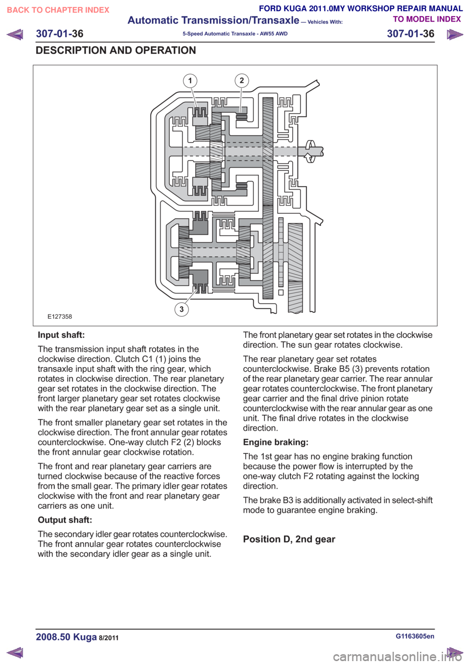
Input shaft:
The transmission input shaft rotates in the
clockwise direction. Clutch C1 (1) joins the
transaxle input shaft with the ring gear, which
rotates in clockwise direction. The rear planetary
gear set rotates in the clockwise direction. The
front larger planetary gear set rotates clockwise
with the rear planetary gear set as a single unit.
The front smaller planetary gear set rotates in the
clockwise direction. The front annular gear rotates
counterclockwise. One-way clutch F2 (2) blocks
the front annular gear clockwise rotation.
The front and rear planetary gear carriers are
turned clockwise because of the reactive forces
from the small gear. The primary idler gear rotates
clockwise with the front and rear planetary gear
carriers as one unit.
Output shaft:
The secondary idler gear rotates counterclockwise.
The front annular gear rotates counterclockwise
with the secondary idler gear as a single unit.The front planetary gear set rotates in the clockwise
direction. The sun gear rotates clockwise.
The rear planetary gear set rotates
counterclockwise. Brake B5 (3) prevents rotation
of the rear planetary gear carrier. The rear annular
gear rotates counterclockwise. The front planetary
gear carrier and the final drive pinion rotate
counterclockwise with the rear annular gear as one
unit. The final drive rotates in the clockwise
direction.
Engine braking:
The 1st gear has no engine braking function
because the power flow is interrupted by the
one-way clutch F2 rotating against the locking
direction.
The brake B3 is additionally activated in select-shift
mode to guarantee engine braking.
Position D, 2nd gear
G1163605en2008.50 Kuga8/2011
307-01-
36
Automatic Transmission/Transaxle
— Vehicles With:
5-Speed Automatic Transaxle - AW55 AWD
307-01- 36
DESCRIPTION AND OPERATION
TO MODEL INDEX
BACK TO CHAPTER INDEX
FORD KUGA 2011.0MY WORKSHOP REPAIR MANUAL
Page 1858 of 2057
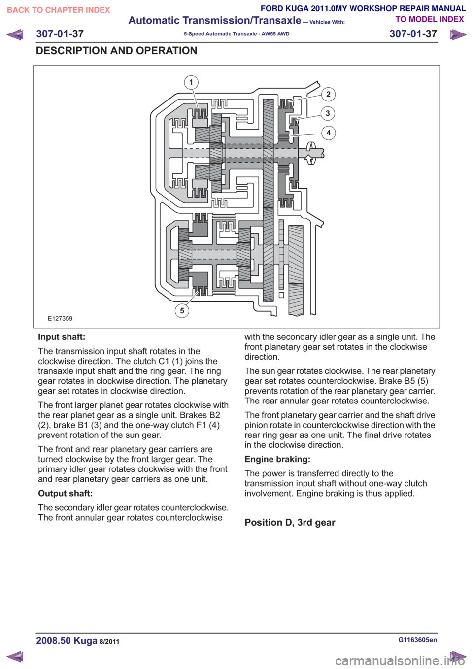
E127359
1
2
3
4
5
Input shaft:
The transmission input shaft rotates in the
clockwise direction. The clutch C1 (1) joins the
transaxle input shaft and the ring gear. The ring
gear rotates in clockwise direction. The planetary
gear set rotates in clockwise direction.
The front larger planet gear rotates clockwise with
the rear planet gear as a single unit. Brakes B2
(2), brake B1 (3) and the one-way clutch F1 (4)
prevent rotation of the sun gear.
The front and rear planetary gear carriers are
turned clockwise by the front larger gear. The
primary idler gear rotates clockwise with the front
and rear planetary gear carriers as one unit.
Output shaft:
The secondary idler gear rotates counterclockwise.
The front annular gear rotates counterclockwisewith the secondary idler gear as a single unit. The
front planetary gear set rotates in the clockwise
direction.
The sun gear rotates clockwise. The rear planetary
gear set rotates counterclockwise. Brake B5 (5)
prevents rotation of the rear planetary gear carrier.
The rear annular gear rotates counterclockwise.
The front planetary gear carrier and the shaft drive
pinion rotate in counterclockwise direction with the
rear ring gear as one unit. The final drive rotates
in the clockwise direction.
Engine braking:
The power is transferred directly to the
transmission input shaft without one-way clutch
involvement. Engine braking is thus applied.
Position D, 3rd gear
G1163605en2008.50 Kuga8/2011
307-01-
37
Automatic Transmission/Transaxle
— Vehicles With:
5-Speed Automatic Transaxle - AW55 AWD
307-01- 37
DESCRIPTION AND OPERATION
TO MODEL INDEX
BACK TO CHAPTER INDEX
FORD KUGA 2011.0MY WORKSHOP REPAIR MANUAL
Page 1859 of 2057
E127360
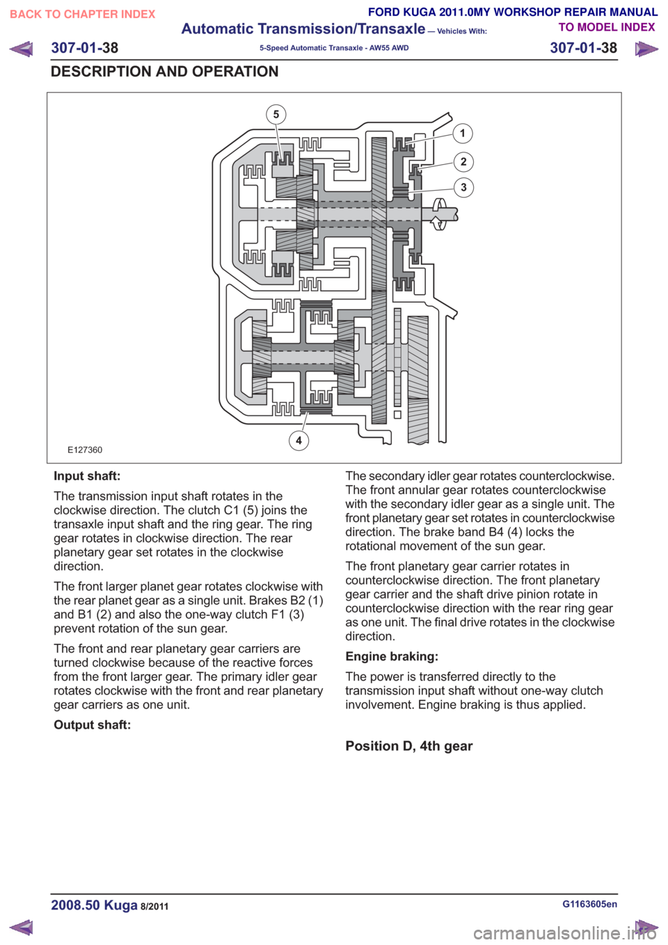
1
2
3
4
5
Input shaft:
The transmission input shaft rotates in the
clockwise direction. The clutch C1 (5) joins the
transaxle input shaft and the ring gear. The ring
gear rotates in clockwise direction. The rear
planetary gear set rotates in the clockwise
direction.
The front larger planet gear rotates clockwise with
the rear planet gear as a single unit. Brakes B2 (1)
and B1 (2) and also the one-way clutch F1 (3)
prevent rotation of the sun gear.
The front and rear planetary gear carriers are
turned clockwise because of the reactive forces
from the front larger gear. The primary idler gear
rotates clockwise with the front and rear planetary
gear carriers as one unit.
Output shaft:The secondary idler gear rotates counterclockwise.
The front annular gear rotates counterclockwise
with the secondary idler gear as a single unit. The
front planetary gear set rotates in counterclockwise
direction. The brake band B4 (4) locks the
rotational movement of the sun gear.
The front planetary gear carrier rotates in
counterclockwise direction. The front planetary
gear carrier and the shaft drive pinion rotate in
counterclockwise direction with the rear ring gear
as one unit. The final drive rotates in the clockwise
direction.
Engine braking:
The power is transferred directly to the
transmission input shaft without one-way clutch
involvement. Engine braking is thus applied.
Position D, 4th gear
G1163605en2008.50 Kuga8/2011
307-01-
38
Automatic Transmission/Transaxle
— Vehicles With:
5-Speed Automatic Transaxle - AW55 AWD
307-01- 38
DESCRIPTION AND OPERATION
TO MODEL INDEX
BACK TO CHAPTER INDEX
FORD KUGA 2011.0MY WORKSHOP REPAIR MANUAL
Page 1860 of 2057
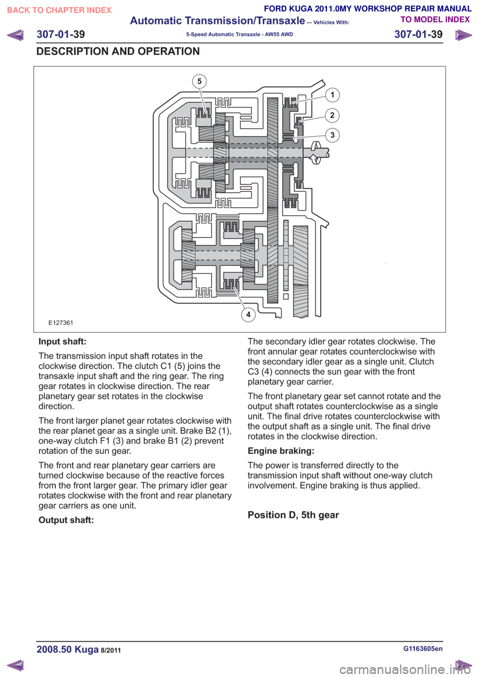
E127361
1
2
3
4
5
Input shaft:
The transmission input shaft rotates in the
clockwise direction. The clutch C1 (5) joins the
transaxle input shaft and the ring gear. The ring
gear rotates in clockwise direction. The rear
planetary gear set rotates in the clockwise
direction.
The front larger planet gear rotates clockwise with
the rear planet gear as a single unit. Brake B2 (1),
one-way clutch F1 (3) and brake B1 (2) prevent
rotation of the sun gear.
The front and rear planetary gear carriers are
turned clockwise because of the reactive forces
from the front larger gear. The primary idler gear
rotates clockwise with the front and rear planetary
gear carriers as one unit.
Output shaft:The secondary idler gear rotates clockwise. The
front annular gear rotates counterclockwise with
the secondary idler gear as a single unit. Clutch
C3 (4) connects the sun gear with the front
planetary gear carrier.
The front planetary gear set cannot rotate and the
output shaft rotates counterclockwise as a single
unit. The final drive rotates counterclockwise with
the output shaft as a single unit. The final drive
rotates in the clockwise direction.
Engine braking:
The power is transferred directly to the
transmission input shaft without one-way clutch
involvement. Engine braking is thus applied.
Position D, 5th gear
G1163605en2008.50 Kuga8/2011
307-01-
39
Automatic Transmission/Transaxle
— Vehicles With:
5-Speed Automatic Transaxle - AW55 AWD
307-01- 39
DESCRIPTION AND OPERATION
TO MODEL INDEX
BACK TO CHAPTER INDEX
FORD KUGA 2011.0MY WORKSHOP REPAIR MANUAL