2011 FORD KUGA light
[x] Cancel search: lightPage 1340 of 2057
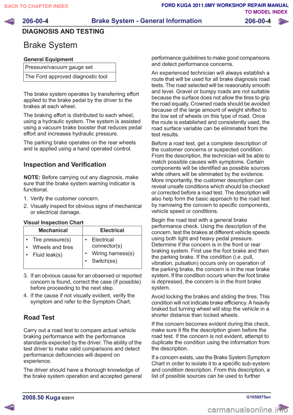
Brake System
General EquipmentPressure/vacuum gauge set
The Ford approved diagnostic tool
The brake system operates by transferring effort
applied to the brake pedal by the driver to the
brakes at each wheel.
The braking effort is distributed to each wheel,
using a hydraulic system. The system is assisted
using a vacuum brake booster that reduces pedal
effort and increases hydraulic pressure.
The parking brake operates on the rear wheels
and is applied using a hand operated control.
Inspection and Verification
NOTE: Before carrying out any diagnosis, make
sure that the brake system warning indicator is
functional.
1. Verify the customer concern.
2. Visually inspect for obvious signs of mechanical or electrical damage.
Visual Inspection Chart
Electrical
Mechanical
• Electricalconnector(s)
• Wiring harness(s)
• Switch(es)
• Tire pressure(s)
• Wheels and tires
• Fluid leak(s)
3. If an obvious cause for an observed or reported concern is found, correct the case (if possible)
before proceeding to the next step.
4. If the cause if not visually evident, verify the symptom and refer to the Symptom Chart.
Road Test
Carry out a road test to compare actual vehicle
braking performance with the performance
standards expected by the driver. The ability of the
test driver to make valid comparisons and detect
performance deficiencies will depend on
experience.
The driver should have a thorough knowledge of
the brake system operation and accepted general performance guidelines to make good comparisons
and detect performance concerns.
An experienced technician will always establish a
route that will be used for all brake diagnosis road
tests. The road selected will be reasonably smooth
and level. Gravel or bumpy roads are not suitable
because the surface does not allow the tires to grip
the road equally. Crowned roads should be avoided
because of the large amount of weight shifted to
the low set of wheels on this type of road. Once
the route is established and consistently used, the
road surface variable can be eliminated from the
test results.
Before a road test, get a complete description of
the customer concerns or suspected condition.
From the description, the technician will be able to
match possible causes with symptoms. Certain
components will be identified as possible sources
while others will be eliminated by the evidence.
More importantly, the customer description can
reveal unsafe conditions which should be checked
or corrected before a road test. The description will
also help form the basic approach to the road test
by narrowing the concern to specific components,
vehicle speed or conditions.
Begin the road test with a general brake
performance check. Using the description of the
concern, test the brakes at different vehicle speeds
using both light and heavy pedal pressure.
Determine if the concern is in the front or rear
braking system. First use the foot brake and then
the parking brake. If the condition (i.e. pull,
vibration, pulsation) occurs only on operation of
the parking brake, the concern is in the rear brake
system. If the condition occurs when the foot brake
is depressed, the concern is in the front brake
system.
Avoid locking the brakes and sliding the tires. This
condition will not indicate brake efficiency. A heavily
braked but turning wheel will stop the vehicle in a
shorter distance than locked wheels.
If the concern becomes evident during this check,
make sure it fits the description given before the
road test. If the concern is not evident, attempt to
duplicate the condition using the information from
the description.
If a concern exists, use the Brake System Symptom
Chart in order to isolate it to a specific sub-system
and condition description. From this description, a
list of possible sources can be used to further
G1058975en2008.50 Kuga8/2011
206-00-
4
Brake System - General Information
206-00- 4
DIAGNOSIS AND TESTING
TO MODEL INDEX
BACK TO CHAPTER INDEX
FORD KUGA 2011.0MY WORKSHOP REPAIR MANUAL
Page 1344 of 2057
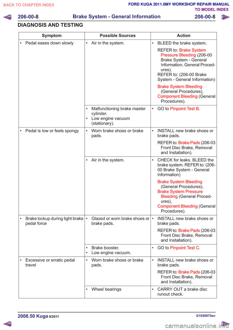
Action
Possible Sources
Symptom
• BLEED the brake system.REFER to: Brake System
Pressure Bleeding (206-00
Brake System - General
Information, General Proced-
ures).
REFER to: (206-00 Brake
System - General Information)
Brake System Bleeding (General Procedures),
Component Bleeding (General
Procedures).
• Air in the system.
• Pedal eases down slowly
• GO toPinpoint Test B.
• Malfunctioning brake master
cylinder.
• Low engine vacuum (stationary).
• INSTALL new brake shoes orbrake pads.
REFER to: Brake Pads (206-03
Front Disc Brake, Removal
and Installation).
• Worn brake shoes or brake
pads.
• Pedal is low or feels spongy
• CHECK for leaks. BLEED thebrake system. REFER to: (206-
00 Brake System - General
Information)
Brake System Bleeding (General Procedures),
Brake System Pressure Bleeding (General Proced-
ures),
Component Bleeding (General
Procedures).
• Air in the system.
• INSTALL new brake shoes orbrake pads.
REFER to: Brake Pads (206-03
Front Disc Brake, Removal
and Installation).
• Glazed or worn brake shoes or
brake pads.
• Brake lockup during light brake
pedal force
• GO toPinpoint Test C.
• Brake booster.
• Low engine vacuum.
• INSTALL new brake shoes orbrake pads.
REFER to: Brake Pads (206-03
Front Disc Brake, Removal
and Installation).
• Worn brake shoes or brake
pads.
• Excessive or erratic pedal
travel
• CARRY OUT a brake discrunout check.
• Wheel bearings
G1058975en2008.50 Kuga8/2011
206-00-
8
Brake System - General Information
206-00- 8
DIAGNOSIS AND TESTING
TO MODEL INDEX
BACK TO CHAPTER INDEX
FORD KUGA 2011.0MY WORKSHOP REPAIR MANUAL
Page 1349 of 2057
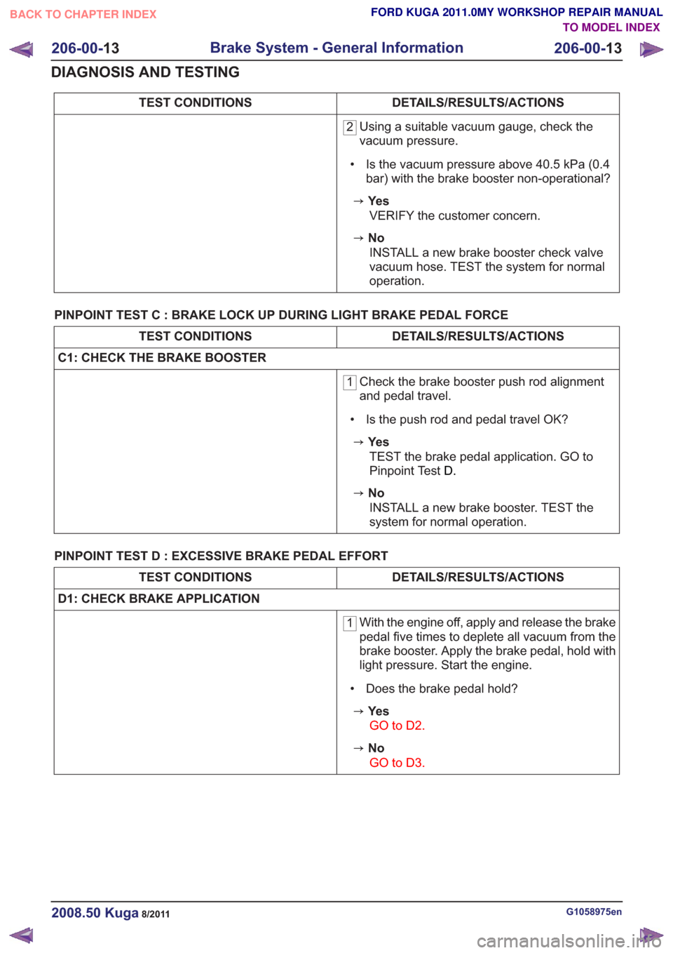
DETAILS/RESULTS/ACTIONS
TEST CONDITIONS
2 Using a suitable vacuum gauge, check the
vacuum pressure.
• Is the vacuum pressure above 40.5 kPa (0.4 bar) with the brake booster non-operational?
zYe s
VERIFY the customer concern.
zNoINSTALL a new brake booster check valve
vacuum hose. TEST the system for normal
operation.
PINPOINT TEST C : BRAKE LOCK UP DURING LIGHT BRAKE PEDAL FORCE
DETAILS/RESULTS/ACTIONS
TEST CONDITIONS
C1: CHECK THE BRAKE BOOSTER
1 Check the brake booster push rod alignment
and pedal travel.
• Is the push rod and pedal travel OK?
zYe s TEST the brake pedal application. GO to
Pinpoint Test D.
zNo
INSTALL a new brake booster. TEST the
system for normal operation.
PINPOINT TEST D : EXCESSIVE BRAKE PEDAL EFFORT
DETAILS/RESULTS/ACTIONS
TEST CONDITIONS
D1: CHECK BRAKE APPLICATION
1 With the engine off, apply and release the brake
pedal five times to deplete all vacuum from the
brake booster. Apply the brake pedal, hold with
light pressure. Start the engine.
• Does the brake pedal hold?
zYe s GO to D2 .
zNo
GO to D3 .
G1058975en2008.50 Kuga8/2011
206-00-13
Brake System - General Information
206-00- 13
DIAGNOSIS AND TESTING
TO MODEL INDEX
BACK TO CHAPTER INDEX
FORD KUGA 2011.0MY WORKSHOP REPAIR MANUAL
Page 1353 of 2057
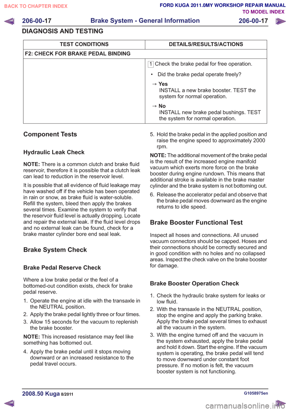
DETAILS/RESULTS/ACTIONS
TEST CONDITIONS
F2: CHECK FOR BRAKE PEDAL BINDING
1 Check the brake pedal for free operation.
• Did the brake pedal operate freely?
zYe s INSTALL a new brake booster. TEST the
system for normal operation.
zNoINSTALL new brake pedal bushings. TEST
the system for normal operation.
Component Tests
Hydraulic Leak Check
NOTE: There is a common clutch and brake fluid
reservoir, therefore it is possible that a clutch leak
can lead to reduction in the reservoir level.
It is possible that all evidence of fluid leakage may
have washed off if the vehicle has been operated
in rain or snow, as brake fluid is water-soluble.
Refill the system, bleed then apply the brakes
several times. Examine the system to verify that
the reservoir fluid level is actually dropping. Locate
and repair the external leak. If the fluid level drops
and no external leak can be found, check for a
brake master cylinder bore end seal leak.
Brake System Check
Brake Pedal Reserve Check
Where a low brake pedal or the feel of a
bottomed-out condition exists, check for brake
pedal reserve.
1. Operate the engine at idle with the transaxle in the NEUTRAL position.
2. Apply the brake pedal lightly three or four times.
3. Allow 15 seconds for the vacuum to replenish the brake booster.
NOTE: This increased resistance may feel like
something has bottomed out.
4. Apply the brake pedal until it stops moving downward or an increased resistance to the
pedal travel occurs. 5. Hold the brake pedal in the applied position and
raise the engine speed to approximately 2000
rpm.
NOTE: The additional movement of the brake pedal
is the result of the increased engine manifold
vacuum which exerts more force on the brake
booster during engine rundown. This means that
additional stroke is available in the brake master
cylinder and the brake system is not bottoming out.
6. Release the accelerator pedal and observe that the brake pedal moves downward as the engine
returns to idle speed.
Brake Booster Functional Test
Inspect all hoses and connections. All unused
vacuum connectors should be capped. Hoses and
their connections should be correctly secured and
in good condition with no holes and no collapsed
areas. Inspect the check valve on the brake booster
for damage.
Brake Booster Operation Check
1. Check the hydraulic brake system for leaks orlow fluid.
2. With the transaxle in the NEUTRAL position, stop the engine and apply the parking brake.
Apply the brake pedal several times to exhaust
all the vacuum in the system.
3. With the engine turned off and the vacuum in the system exhausted, apply the brake pedal
and hold it down. Start the engine. If the vacuum
system is operating, the brake pedal will tend
to move downward under constant foot
pressure. If no motion is felt, the vacuum
booster system is not functioning.
G1058975en2008.50 Kuga8/2011
206-00- 17
Brake System - General Information
206-00- 17
DIAGNOSIS AND TESTING
TO MODEL INDEX
BACK TO CHAPTER INDEX
FORD KUGA 2011.0MY WORKSHOP REPAIR MANUAL
Page 1354 of 2057
4. Remove the vacuum hose from the brakebooster. Manifold vacuum should be available
at the brake booster end of the hose with the
engine at idle speed and the transaxle in the
NEUTRAL position. Make sure that all unused
vacuum outlets are correctly capped, hose
connectors are correctly secured and vacuum
hoses are in good condition. When it is
established that manifold vacuum is available
to the brake booster, connect the vacuum hose
to the brake booster and repeat Step 3. If no
downward movement of the brake pedal is felt,
install a new brake booster.
5. Operate the engine a minimum of 10 seconds at approximately 1200 rpm. Stop the engine and
let the vehicle stand for 10 minutes. Then, apply
the brake pedal with approximately 89 N (20 lb)
force. The pedal feel (brake application) should
be the same as that noted with the engine
operating. If the brake pedal feels hard (no
power assist), install a new vacuum check valve
and then repeat the test. If the brake pedal still
feels hard, install a new brake booster. If the
brake pedal movement feels spongy, bleed the
brake system. REFER to: (206-00 Brake System
- General Information)
Brake System Bleeding (General Procedures),
Brake System Pressure Bleeding (General
Procedures),
Component Bleeding (General Procedures).
Brake Master Cylinder
Usually, the first and strongest indicator of anything
wrong with the braking system is a feeling through
the brake pedal. In diagnosing the condition of the
brake master cylinder, check pedal feel as
evidence of a brake concern. Check for the red
brake warning indicator illumination and the fluid
level in the master cylinder reservoir.
Normal Conditions
The following conditions are considered normal
and are not indications that the brake master
cylinder is in need of service.
– Modern brake systems are not designed to
produce as hard a pedal effort as in the past.
Complaints of light pedal efforts should be compared to pedal efforts of another vehicle, of
the same model and year.
– During normal operation of the brake pedal, the fluid level in the reservoir will rise during brake
pedal application and fall during release. The
net fluid level (i.e., after brake pedal application
and release) will remain unchanged.
– A trace of brake fluid will exists on the brake booster shell below the master cylinder
mounting flange. This results from the normal
lubricating action of the master cylinder bore
end seal.
– The fluid level will fall with brake shoe and lining wear.
Abnormal Conditions
NOTE: Prior to performing any diagnosis, make
sure the brake system warning indicator is
functional.
Changes in brake pedal feel or travel are indicators
that something could be wrong with the braking
system. The diagnostic procedure and techniques
use brake pedal feel, warning indicator illumination
and low brake fluid level as indicators in diagnosing
braking system concerns. The following conditions
are considered abnormal and indicate that the
brake master cylinder is in need of service.
– The brake pedal goes down fast. This could be caused by an external or internal leak.
– The brake pedal eases down slowly. This could be caused by an external or internal leak.
– The brake pedal is low and or feels spongy. This condition may be caused by no fluid in the brake
master cylinder reservoir, reservoir cap vent
holes clogged or air in the hydraulic system.
– The brake pedal effort is excessive. This may be caused by a bind or obstruction in the pedal
or linkage, clogged fluid control valve or
insufficient booster vacuum.
– The rear brakes lock up during light pedal force. This may be caused by incorrect tire pressures,
grease or fluid on the brake shoes and linings,
damaged brake shoes and linings, incorrectly
adjusted parking brake, or damaged or
contaminated brake pressure control valves.
– The brake pedal effort is erratic. This condition could be caused by a brake booster malfunction,
extreme caliper piston knock back or incorrectly
installed brake shoes and linings.
– The red brake warning indicator is ON. This may be caused by low fluid level, ignition wire routing
G1058975en2008.50 Kuga8/2011
206-00- 18
Brake System - General Information
206-00- 18
DIAGNOSIS AND TESTING
TO MODEL INDEX
BACK TO CHAPTER INDEX
FORD KUGA 2011.0MY WORKSHOP REPAIR MANUAL
Page 1426 of 2057
Description
Item
D.C. motor
9
Solenoid-operated pilot valve (2 off)
10
Solenoid-operated priming valve (2 off)
11
One way check valve
12
Low-pressure accumulator (2 off)
13
Solenoid-operated inlet valve (RH rear
brake)
14
Solenoid-operated inlet valve (LH front
brake)
15
Solenoid-operated outlet valve (LH front
brake)
16
Solenoid-operated outlet valve (RH rear
brake)
17Description
Item
Pressure sensor (5 off)
18
LH front brake (secondary circuit)
19
RH rear brake (secondary circuit)
20
LH rear brake (primary circuit)
21
RH front brake (primary circuit)
22
Solenoid-operated outlet valve (RH front
brake)
23
Solenoid-operated outlet valve (LH rear
brake)
24
Solenoid-operated inlet valve (LH rear
brake)
25
Solenoid-operated inlet valve (RH front
brake)
26
System Operation
The HCU features 3 operating modes:
Normal braking:
Initially, no current is supplied to
any of the solenoid-operated valves. Operating the
brake pedal produces a corresponding increase
or decrease of pressure in the brakes, through the
open pilot valves and inlet valves. If the ABS
module determines that EBD is necessary, it
energizes the inlet valves for both the rear brakes,
to isolate the brakes from any further increase in
hydraulic pressure.
ABS braking: If the ABS module determines that
ABS braking is necessary, it actuates the inlet and
outlet valves of the relevant brake and starts the
hydraulic return pump. The inlet valve closes to
isolate the brake from pressurized fluid; the outlet
valve opens to release pressure from the brake
into the accumulator and the return pump circuit.
The brake releases slightly and the wheel starts to turn again. The ABS control unit then operates the
inlet and outlet valves to regulate the hydraulic
pressure acting on the brake in order to maximize
braking effect without the wheel locking up. Control
of the valves for each wheel takes place
individually.
Active braking:
With active braking, pressure is
generated for other braking functions than the
normal and ABS braking systems, e.g. for the ESP
and TCS systems. For active braking, the ABS
module energizes the pilot valves and priming
valves, starts the return pump and energizes all of
the inlet valves. Brake fluid, drawn from the
reservoir through the master cylinder and priming
valve, is pressurized by the return pump and
supplied to the inlet valves. The ABS control unit
then actuates the inlet and outlet valves in order
to regulate the pressure for the individual brakes.
Some noise may be generated during active
braking.
G1001304en2008.50 Kuga8/2011
206-09B- 8
Anti-Lock Control - Stability Assist
206-09B- 8
DESCRIPTION AND OPERATION
TO MODEL INDEX
BACK TO CHAPTER INDEX
FORD KUGA 2011.0MY WORKSHOP REPAIR MANUAL
Page 1429 of 2057
HCU to check for sudden actuation of the brakes.
With the brake pedal pressed, the ABS module
triggers emergency braking if the rate of increase
of hydraulic pressure exceeds the predetermined
limit.
If the brake pedal is pressed so hard that the ABS
becomes active on the front wheels then the ABS
control unit increases the pressure to the rear
wheel brakes up to the ABS intervention threshold.
EBA operation continues until the driver releases
the brake pedal sufficiently for the hydraulic
pressure in the HCU to drop below a threshold
value stored in the ABS module.
Trailer stability control:If the vehicle is ordered
with a trailer coupling then the Trailer Stability
Control function is integrated in the ESP. The ESP
detects snaking when driving with a trailer and
reduces the speed of the vehicle and trailer through
adapted braking and, if necessary, by also reducing
the engine output until the snaking movement of
the trailer is corrected.
Roll-over protection: The ESP dynamically
determines the tipping tendency of the vehicle and
works in conjunction with the EBA system to
prevent the vehicle from tipping over during
dynamic maneuvers like lane changing or while
negotiating bends.
Emergency brake light: The emergency brake
light automatically switches on the hazard flasher
system to warn drivers of other vehicles that
emergency braking is being initiated. Based on a
defined delay value, the ABS/ESP module sends
a signal to the generic electronic module (GEM)
via the CAN data bus. The GEM activates the
hazard flasher system, that then flashes 7 times.
Prerequisites for activation of the emergency brake
light are:
• The speed is higher than 50 km/h.
• The brake pedal is being actuated.
• The deceleration is greater than 9 m/s².
To prevent activation on snow or ice, for example,
the following prerequisites must be met:
• The speed is higher than 50 km/h.
• The brake pedal is being actuated.
• ABS regulation takes place.
• The deceleration is greater than 6 m/s².
Tire pressure monitoring system: The tire
pressure monitoring system used in the Kuga is
able to detect loss of air in a tire at an early stage
and warn the driver. Because it can only compare
the behaviour of the tyres with each other, it is not possible to draw conclusions about the absolute
tyre pressure. It is also not possible to monitor the
spare tyre pressure. In order for the system to
operate correctly, the tyre pressures must be
regularly checked and corrected and the system
subsequently initialised (see below).
The tire pressure monitoring system used here,
depending on the equipment level, is built into the
anti-lock braking system (ABS) as an extra function
and therefore does not have its own sensors.
The ABS module measures the loss of pressure
in the tyres by calculation using the wheel speed
sensors of the ABS system. If a tyre loses
pressure, its diameter decreases and the speed of
the wheel therefore increases. If the ABS module
detects such a loss in pressure, it sends a signal
to the instrument cluster via the CAN bus and a
warning message is displayed in the message
centre. The warning threshold depends among
other things on the dimension of the tyres being
used, the vehicle operating conditions and the
status at the last initialisation. Since neither the
absolute tyre pressure nor the position of the tyre
is known, the pressure of all the tyres must be
checked and the system re-initialised after a tyre
pressure warning. If necessary, the cause of the
loss of pressure must be investigated.
Regular tyre pressure checks are still necessary.
The system must be initialised after a tyre is
changed, winter or summer tyres fitted, the
pressures corrected or adjusted to suit the vehicle
load. This can be done by the driver using the
driver information system. For further information,
see: Owner’s Manual.
Component Description
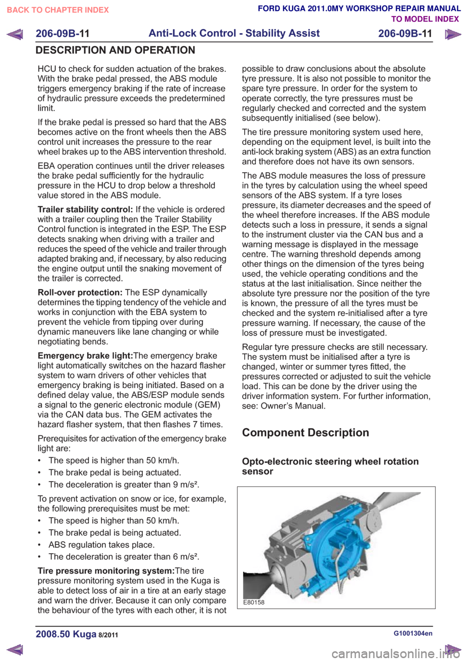
Opto-electronic steering wheel rotation
sensor
E80158
G1001304en2008.50 Kuga8/2011
206-09B-
11
Anti-Lock Control - Stability Assist
206-09B- 11
DESCRIPTION AND OPERATION
TO MODEL INDEX
BACK TO CHAPTER INDEX
FORD KUGA 2011.0MY WORKSHOP REPAIR MANUAL
Page 1430 of 2057
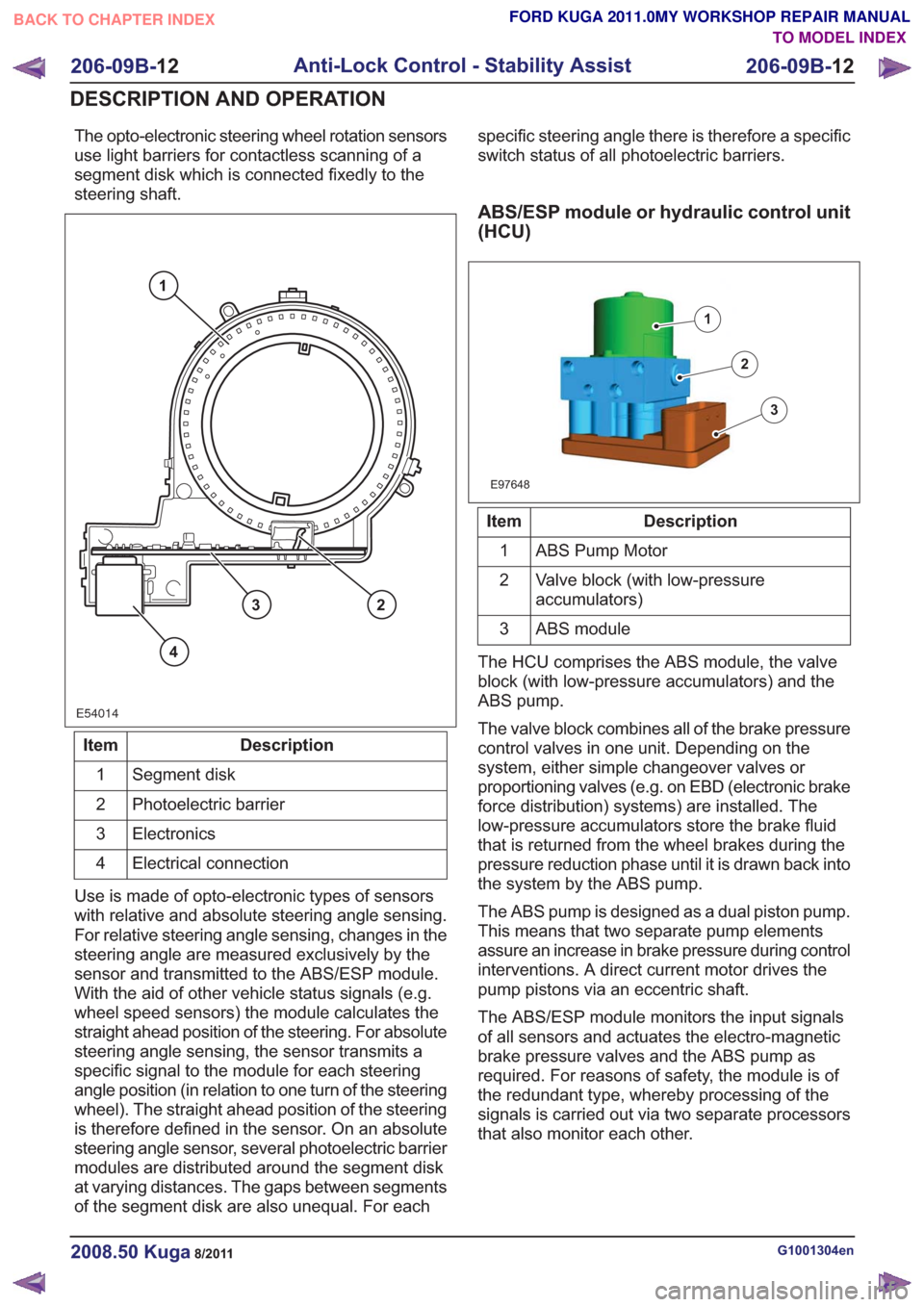
The opto-electronic steering wheel rotation sensors
use light barriers for contactless scanning of a
segment disk which is connected fixedly to the
steering shaft.
E54014
1
23
4
Description
Item
Segment disk
1
Photoelectric barrier
2
Electronics
3
Electrical connection
4
Use is made of opto-electronic types of sensors
with relative and absolute steering angle sensing.
For relative steering angle sensing, changes in the
steering angle are measured exclusively by the
sensor and transmitted to the ABS/ESP module.
With the aid of other vehicle status signals (e.g.
wheel speed sensors) the module calculates the
straight ahead position of the steering. For absolute
steering angle sensing, the sensor transmits a
specific signal to the module for each steering
angle position (in relation to one turn of the steering
wheel). The straight ahead position of the steering
is therefore defined in the sensor. On an absolute
steering angle sensor, several photoelectric barrier
modules are distributed around the segment disk
at varying distances. The gaps between segments
of the segment disk are also unequal. For each specific steering angle there is therefore a specific
switch status of all photoelectric barriers.
ABS/ESP module or hydraulic control unit
(HCU)
E97648
1
2
3
Description
Item
ABS Pump Motor
1
Valve block (with low-pressure
accumulators)
2
ABS module
3
The HCU comprises the ABS module, the valve
block (with low-pressure accumulators) and the
ABS pump.
The valve block combines all of the brake pressure
control valves in one unit. Depending on the
system, either simple changeover valves or
proportioning valves (e.g. on EBD (electronic brake
force distribution) systems) are installed. The
low-pressure accumulators store the brake fluid
that is returned from the wheel brakes during the
pressure reduction phase until it is drawn back into
the system by the ABS pump.
The ABS pump is designed as a dual piston pump.
This means that two separate pump elements
assure an increase in brake pressure during control
interventions. A direct current motor drives the
pump pistons via an eccentric shaft.
The ABS/ESP module monitors the input signals
of all sensors and actuates the electro-magnetic
brake pressure valves and the ABS pump as
required. For reasons of safety, the module is of
the redundant type, whereby processing of the
signals is carried out via two separate processors
that also monitor each other.
G1001304en2008.50 Kuga8/2011
206-09B- 12
Anti-Lock Control - Stability Assist
206-09B- 12
DESCRIPTION AND OPERATION
TO MODEL INDEX
BACK TO CHAPTER INDEX
FORD KUGA 2011.0MY WORKSHOP REPAIR MANUAL