2011 FORD KUGA light
[x] Cancel search: lightPage 1432 of 2057
E53340
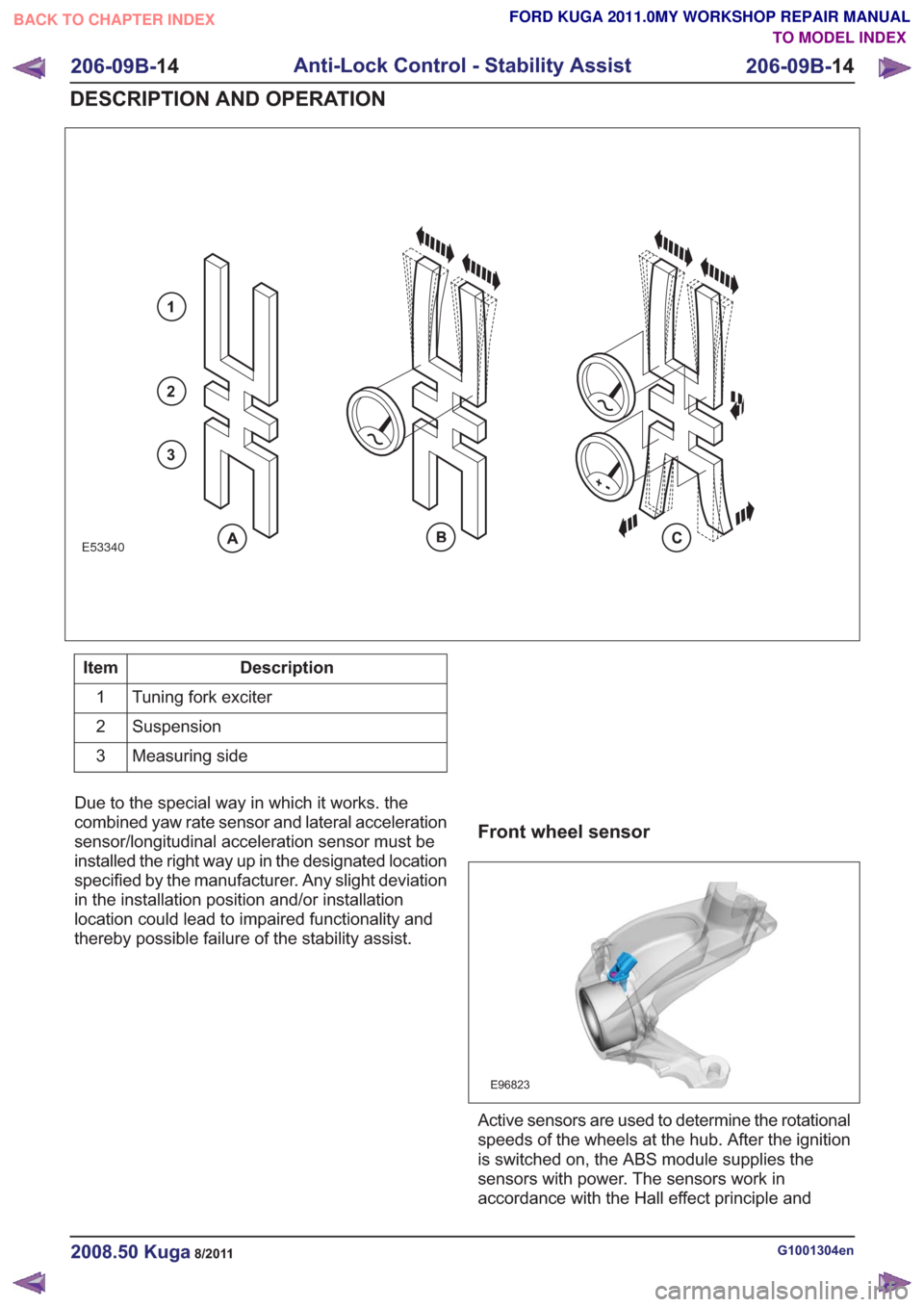
1
2
3
Description
Item
Tuning fork exciter
1
Suspension
2
Measuring side
3
Due to the special way in which it works. the
combined yaw rate sensor and lateral acceleration
sensor/longitudinal acceleration sensor must be
installed the right way up in the designated location
specified by the manufacturer. Any slight deviation
in the installation position and/or installation
location could lead to impaired functionality and
thereby possible failure of the stability assist.
Front wheel sensor
E96823
Active sensors are used to determine the rotational
speeds of the wheels at the hub. After the ignition
is switched on, the ABS module supplies the
sensors with power. The sensors work in
accordance with the Hall effect principle and
G1001304en2008.50 Kuga8/2011
206-09B- 14
Anti-Lock Control - Stability Assist
206-09B- 14
DESCRIPTION AND OPERATION
TO MODEL INDEX
BACK TO CHAPTER INDEX
FORD KUGA 2011.0MY WORKSHOP REPAIR MANUAL
Page 1527 of 2057
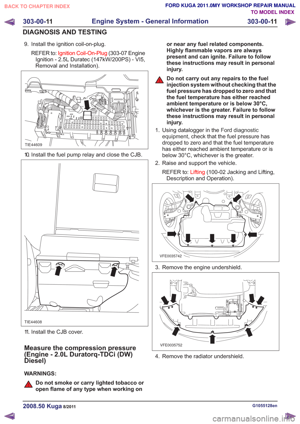
9. Install the ignition coil-on-plug.REFER to: Ignition Coil-On-Plug (303-07 Engine
Ignition - 2.5L Duratec (147kW/200PS) - VI5,
Removal and Installation).
TIE44609
10. Install the fuel pump relay and close the CJB.
TIE44608
11. Install the CJB cover.
Measure the compression pressure
(Engine - 2.0L Duratorq-TDCi (DW)
Diesel)
WARNINGS:
Do not smoke or carry lighted tobacco or
open flame of any type when working on or near any fuel related components.
Highly flammable vapors are always
present and can ignite. Failure to follow
these instructions may result in personal
injury.
Do not carry out any repairs to the fuel
injection system without checking that the
fuel pressure has dropped to zero and that
the fuel temperature has either reached
ambient temperature or is below 30°C,
whichever is the greater. Failure to follow
these instructions may result in personal
injury.
1. Using datalogger in the Ford diagnostic
equipment , check that the fuel pressure has
dropped to zero and that the fuel temperature
has either reached ambient temperature or is
below 30°C, whichever is the greater.
2. Raise and support the vehicle.
REFER to: Lifting(100-02 Jacking and Lifting,
Description and Operation).
VFE0035742
3. Remove the engine undershield.
VFE0035752
4. Remove the radiator undershield.
G1055128en2008.50 Kuga8/2011
303-00- 11
Engine System - General Information
303-00- 11
DIAGNOSIS AND TESTING
TO MODEL INDEX
BACK TO CHAPTER INDEX
FORD KUGA 2011.0MY WORKSHOP REPAIR MANUAL
Page 1748 of 2057
Description
Item
Vehicles with manual transaxle.
A
If equipped with an automatic transaxle.
B
Ignition key
Comments:With transponder for PATS (passive
anti-theft system)
1
PAT S
2
Ignition lock
3
GEM (generic electronic module)
4
PCM (powertrain control module)
5
Battery
6Description
Item
Starter relay
7
Starter motor
8
Stoplight Switch
Comments:If equipped with an automatic transaxle.
9
TCM (transmission control module)
Comments:If equipped with an automatic transaxle.
10
Starting deactivation relay
Comments:If equipped with an automatic transaxle.
11
G1032961en2008.50 Kuga8/2011
303-06-
4
Starting System— 2.5L Duratec (147kW/200PS) - VI5303-06-
4
DESCRIPTION AND OPERATION
TO MODEL INDEX
BACK TO CHAPTER INDEX
FORD KUGA 2011.0MY WORKSHOP REPAIR MANUAL
Page 1752 of 2057
Description
Item
Start/stop button
1
Keyless vehicle module
2
Electronic steering lock with mount -
passive key and PATS transmitter/receiver
unit
Comments:for emergency start function
3
Radio frequency receiver
Comments:Signal is only executed in GEM
4Description
Item
GEM
5
Stoplight Switch
6
TCM7
Starting deactivation relay
8
PCM
9
Starter relay
10
Starter motor
11
Battery
12
System Operation
Smart Start
The PCM enables the starting process when a key
providing a valid code is read via the PATS. This
code is then verified in the GEM and compared
with the saved code. If this code is recognized as
correct, synchronization with other modules is
carried out. After successful synchronization, the
engine is cleared to start in the PCM. The PCM
connects earth to the starter relay, which then
connects power to the starter solenoid. As soon
as the engine reaches a certain speed, the PCM
disconnects the starter relay and so turns off the
starter. This protects the starter.
If the engine does not turn or turns only slowly, the
starting process is aborted by the PCM.
The starter is notactivated if:
• the engine is running (i.e. the engine speed is above a particular value),
• the PATS does not permit the engine to be started,
• the clutch pedal is not operated (vehicles with manual transmission),
• the gear selector level is not set to P or N (vehicles with automatic transmission),
• the brake pedal is not operated (vehicles with automatic transmission).
Emergency starting function
If the keyless vehicle system is unable to recognize
the passive key, the vehicle can be started via the
emergency starting function. In this case, there is a passive key mount on the
steering wheel. A PATS transmission/reception
unit is attached to this.
To start the engine, the passive key must be
inserted into the passive key mount. The Start/Stop
button can then be used to turn on the ignition and
start the engine as normal. To deactivate the
PATS, a transponder is fitted in the passive key,
which is read by the transmission/reception unit.
G1032961en2008.50 Kuga8/2011
303-06-
8
Starting System— 2.5L Duratec (147kW/200PS) - VI5303-06-
8
DESCRIPTION AND OPERATION
TO MODEL INDEX
BACK TO CHAPTER INDEX
FORD KUGA 2011.0MY WORKSHOP REPAIR MANUAL
Page 1783 of 2057
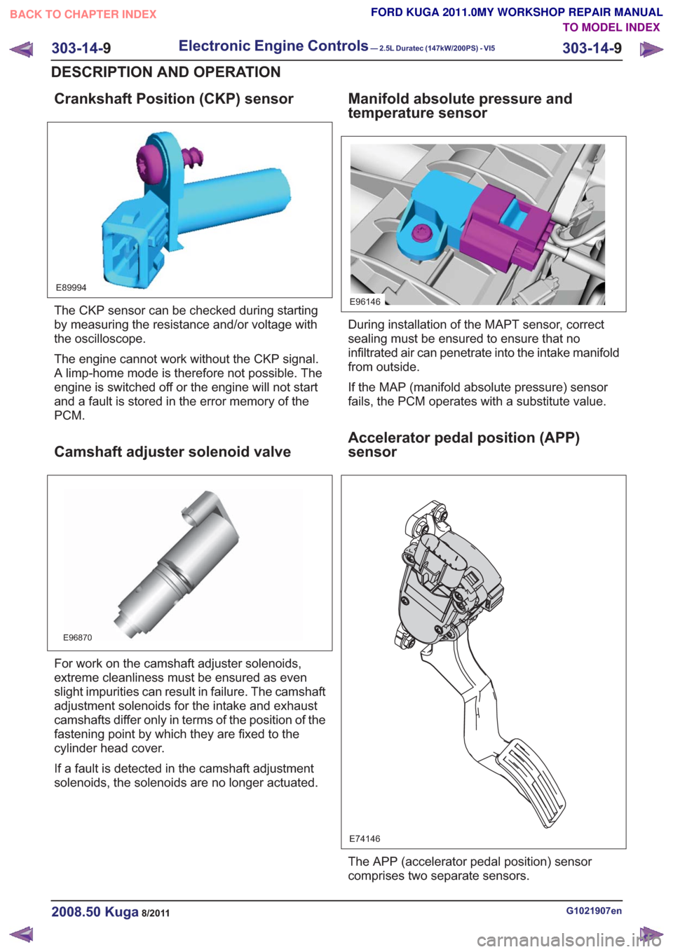
Crankshaft Position (CKP) sensor
E89994
The CKP sensor can be checked during starting
by measuring the resistance and/or voltage with
the oscilloscope.
The engine cannot work without the CKP signal.
A limp-home mode is therefore not possible. The
engine is switched off or the engine will not start
and a fault is stored in the error memory of the
PCM.
Camshaft adjuster solenoid valve
E96870
For work on the camshaft adjuster solenoids,
extreme cleanliness must be ensured as even
slight impurities can result in failure. The camshaft
adjustment solenoids for the intake and exhaust
camshafts differ only in terms of the position of the
fastening point by which they are fixed to the
cylinder head cover.
If a fault is detected in the camshaft adjustment
solenoids, the solenoids are no longer actuated.
Manifold absolute pressure and
temperature sensor
E96146
During installation of the MAPT sensor, correct
sealing must be ensured to ensure that no
infiltrated air can penetrate into the intake manifold
from outside.
If the MAP (manifold absolute pressure) sensor
fails, the PCM operates with a substitute value.
Accelerator pedal position (APP)
sensor
E74146
The APP (accelerator pedal position) sensor
comprises two separate sensors.
G1021907en2008.50 Kuga8/2011
303-14-9
Electronic Engine Controls— 2.5L Duratec (147kW/200PS) - VI5303-14-
9
DESCRIPTION AND OPERATION
TO MODEL INDEX
BACK TO CHAPTER INDEX
FORD KUGA 2011.0MY WORKSHOP REPAIR MANUAL
Page 1784 of 2057
If one of the two APP sensors fails, then only a
proportion of the engine's power will be available
when accelerating. Top speed can nevertheless
be achieved.
If both of the APP sensors fail, the engine is
regulated to a defined speed following a plausibility
check after the BPP (brake pedal position) switch
and brake light switch have been actuated once.
The vehicle can then only be accelerated to a
defined speed.
In either case, a fault is saved in the error memory
of the PCM.
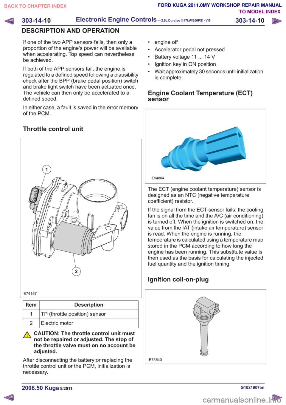
Throttle control unit
E74167
1
2
Description
Item
TP (throttle position) sensor
1
Electric motor
2
CAUTION: The throttle control unit must
not be repaired or adjusted. The stop of
the throttle valve must on no account be
adjusted.
After disconnecting the battery or replacing the
throttle control unit or the PCM, initialization is
necessary. • engine off
• Accelerator pedal not pressed
• Battery voltage 11 ... 14 V
• Ignition key in ON position
• Wait approximately 30 seconds until initialization
is complete.
Engine Coolant Temperature (ECT)
sensor
E94804
The ECT (engine coolant temperature) sensor is
designed as an NTC (negative temperature
coefficient) resistor.
If the signal from the ECT sensor fails, the cooling
fan is on all the time and the A/C (air conditioning)
is turned off. When the ignition is switched on, the
value from the IAT (intake air temperature) sensor
is read. When the engine is running, the
temperature is calculated using a temperature map
stored in the PCM according to how long the
engine has been running. This substitute value is
then used as the basis for calculating the injected
fuel quantity and the ignition timing.
Ignition coil-on-plug
E73540
G1021907en2008.50 Kuga8/2011
303-14- 10
Electronic Engine Controls— 2.5L Duratec (147kW/200PS) - VI5303-14-
10
DESCRIPTION AND OPERATION
TO MODEL INDEX
BACK TO CHAPTER INDEX
FORD KUGA 2011.0MY WORKSHOP REPAIR MANUAL
Page 1792 of 2057
• Torque reduction request (stability assistmodule)
• Cruise control request
The PCM sends the following signals via the CAN
databus:
• Fuel pump relay on/off
• Engine speed
• Warning lights on/off (MIL (malfunction indicator lamp), battery warning lamp)
• PAT S
•ECT
• Air conditioning pressure transducer
• Outside air temperature
With the aid of the input and output signals listed
above, the PCM controls / regulates engine
starting, fuel injection and fuel pressure, ignition,
boost pressure, camshaft adjustment, tank purging,
the radiator fan and the refrigerant compressor.
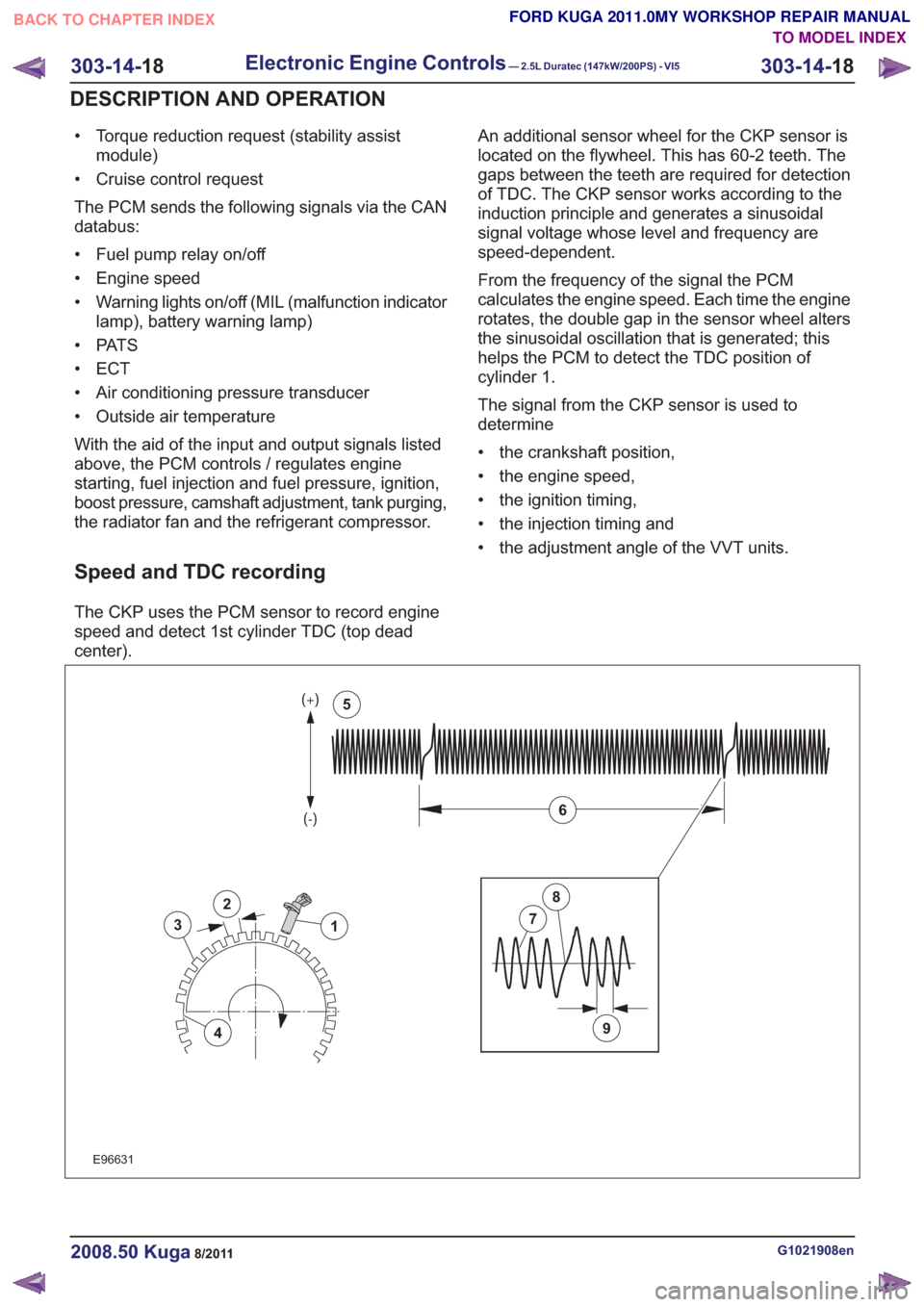
Speed and TDC recording
The CKP uses the PCM sensor to record engine
speed and detect 1st cylinder TDC (top dead
center). An additional sensor wheel for the CKP sensor is
located on the flywheel. This has 60-2 teeth. The
gaps between the teeth are required for detection
of TDC. The CKP sensor works according to the
induction principle and generates a sinusoidal
signal voltage whose level and frequency are
speed-dependent.
From the frequency of the signal the PCM
calculates the engine speed. Each time the engine
rotates, the double gap in the sensor wheel alters
the sinusoidal oscillation that is generated; this
helps the PCM to detect the TDC position of
cylinder 1.
The signal from the CKP sensor is used to
determine
• the crankshaft position,
• the engine speed,
• the ignition timing,
• the injection timing and
• the adjustment angle of the VVT units.
2
3
4
1
9
7
8
6
5
2
3
4
1
9
7
8
6
5
E96631
G1021908en2008.50 Kuga8/2011
303-14-
18
Electronic Engine Controls— 2.5L Duratec (147kW/200PS) - VI5303-14-
18
DESCRIPTION AND OPERATION
TO MODEL INDEX
BACK TO CHAPTER INDEX
FORD KUGA 2011.0MY WORKSHOP REPAIR MANUAL
Page 1793 of 2057
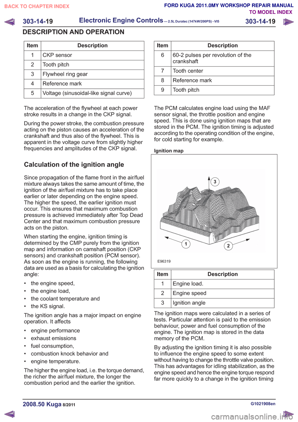
Description
Item
CKP sensor
1
Tooth pitch
2
Flywheel ring gear
3
Reference mark
4
Voltage (sinusoidal-like signal curve)
5Description
Item
60-2 pulses per revolution of the
crankshaft
6
Tooth center
7
Reference mark
8
Tooth pitch
9
The acceleration of the flywheel at each power
stroke results in a change in the CKP signal.
During the power stroke, the combustion pressure
acting on the piston causes an acceleration of the
crankshaft and thus also of the flywheel. This is
apparent in the voltage curve from slightly higher
frequencies and amplitudes of the CKP signal.
Calculation of the ignition angle
Since propagation of the flame front in the air/fuel
mixture always takes the same amount of time, the
ignition of the air/fuel mixture has to take place
earlier or later depending on the engine speed.
The higher the speed, the earlier ignition must
occur. This ensures that maximum combustion
pressure is achieved immediately after Top Dead
Center and that maximum combustion pressure
acts on the piston.
When starting the engine, ignition timing is
determined by the CMP purely from the ignition
map and information on camshaft position (CKP
sensors) and crankshaft position (PCM sensor).
As soon as the engine is running, the following
data are used as a basis for calculating the ignition
angle:
• the engine speed,
• the engine load,
• the coolant temperature and
• the KS signal.
The ignition angle has a major impact on engine
operation. It affects
• engine performance
• exhaust emissions
• fuel consumption,
• combustion knock behavior and
• engine temperature.
The higher the engine load, i.e. the torque demand,
the richer the air/fuel mixture, the longer the
combustion period and the earlier the ignition. The PCM calculates engine load using the MAF
sensor signal, the throttle position and engine
speed. This is done using ignition maps that are
stored in the PCM. The ignition timing is adjusted
according to the operating condition of the engine,
for cold starting for example.
Ignition map
2
E96319
1
3
Description
Item
Engine load.
1
Engine speed
2
Ignition angle
3
The ignition maps were calculated in a series of
tests. Particular attention is paid to the emission
behaviour, power and fuel consumption of the
engine. The ignition map is stored in the data
memory of the PCM.
By adjusting the ignition timing it is also possible
to influence the engine speed to some extent
without having to change the throttle valve position.
This has advantages for idling stabilization, as the
engine speed and hence the engine torque respond
far more quickly to a change in the ignition timing
G1021908en2008.50 Kuga8/2011
303-14- 19
Electronic Engine Controls— 2.5L Duratec (147kW/200PS) - VI5303-14-
19
DESCRIPTION AND OPERATION
TO MODEL INDEX
BACK TO CHAPTER INDEX
FORD KUGA 2011.0MY WORKSHOP REPAIR MANUAL