2011 FORD KUGA light
[x] Cancel search: lightPage 1986 of 2057
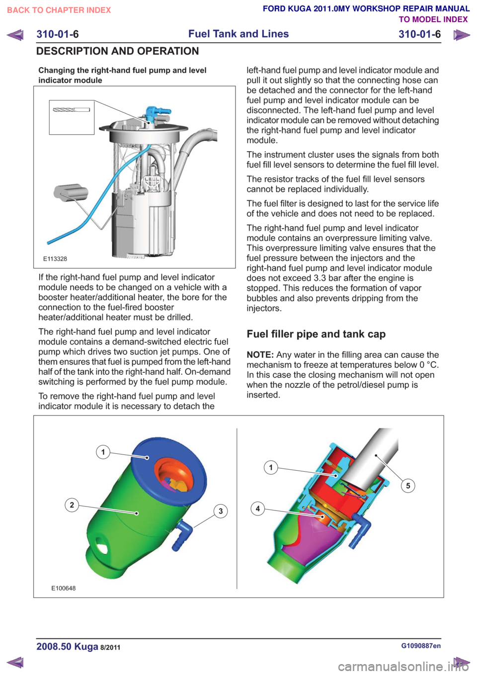
Changing the right-hand fuel pump and level
indicator module
E113328
If the right-hand fuel pump and level indicator
module needs to be changed on a vehicle with a
booster heater/additional heater, the bore for the
connection to the fuel-fired booster
heater/additional heater must be drilled.
The right-hand fuel pump and level indicator
module contains a demand-switched electric fuel
pump which drives two suction jet pumps. One of
them ensures that fuel is pumped from the left-hand
half of the tank into the right-hand half. On-demand
switching is performed by the fuel pump module.
To remove the right-hand fuel pump and level
indicator module it is necessary to detach theleft-hand fuel pump and level indicator module and
pull it out slightly so that the connecting hose can
be detached and the connector for the left-hand
fuel pump and level indicator module can be
disconnected. The left-hand fuel pump and level
indicator module can be removed without detaching
the right-hand fuel pump and level indicator
module.
The instrument cluster uses the signals from both
fuel fill level sensors to determine the fuel fill level.
The resistor tracks of the fuel fill level sensors
cannot be replaced individually.
The fuel filter is designed to last for the service life
of the vehicle and does not need to be replaced.
The right-hand fuel pump and level indicator
module contains an overpressure limiting valve.
This overpressure limiting valve ensures that the
fuel pressure between the injectors and the
right-hand fuel pump and level indicator module
does not exceed 3.3 bar after the engine is
stopped. This reduces the formation of vapor
bubbles and also prevents dripping from the
injectors.
Fuel filler pipe and tank cap
NOTE:
Any water in the filling area can cause the
mechanism to freeze at temperatures below 0 °C.
In this case the closing mechanism will not open
when the nozzle of the petrol/diesel pump is
inserted.
43
1
2
1
5
43
1
2
1
5
E100648
G1090887en2008.50 Kuga8/2011
310-01- 6
Fuel Tank and Lines
310-01- 6
DESCRIPTION AND OPERATION
TO MODEL INDEX
BACK TO CHAPTER INDEX
FORD KUGA 2011.0MY WORKSHOP REPAIR MANUAL
Page 1988 of 2057
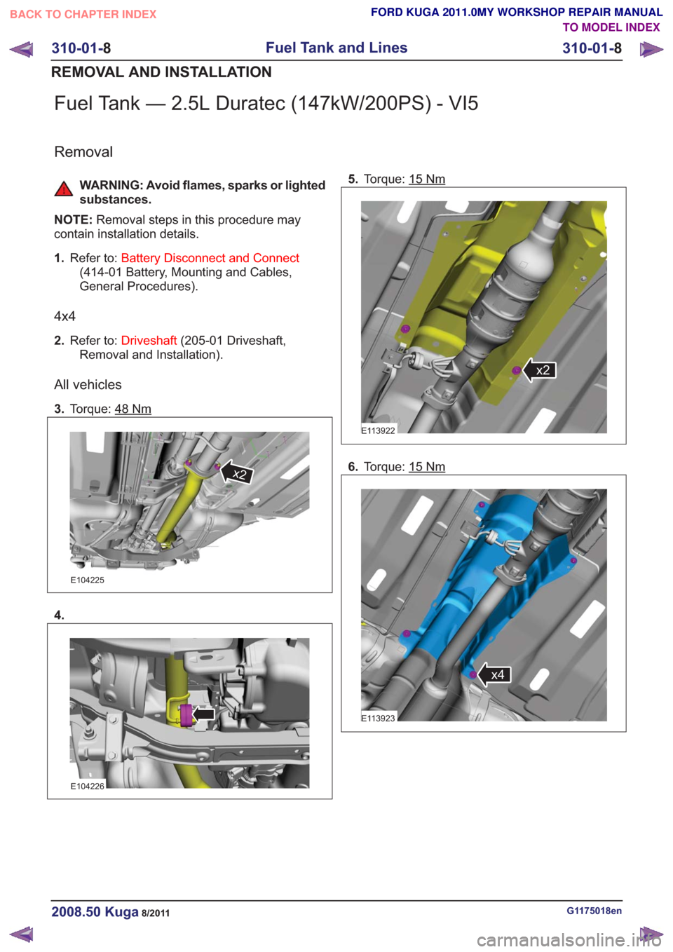
Fuel Tank — 2.5L Duratec (147kW/200PS) - VI5
Removal
WARNING: Avoid flames, sparks or lighted
substances.
NOTE: Removal steps in this procedure may
contain installation details.
1. Refer to: Battery Disconnect and Connect
(414-01 Battery, Mounting and Cables,
General Procedures).
4x4
2. Refer to: Driveshaft (205-01 Driveshaft,
Removal and Installation).
All vehicles
3. Torque: 48Nm
x2x2
E104225
4.
E104226
5.Torque: 15Nm
E113922
x2
6.Torque: 15Nm
x4x4
E113923
G1175018en2008.50 Kuga8/2011
310-01- 8
Fuel Tank and Lines
310-01- 8
REMOVAL AND INSTALLATION
TO MODEL INDEX
BACK TO CHAPTER INDEX
FORD KUGA 2011.0MY WORKSHOP REPAIR MANUAL
Page 1994 of 2057
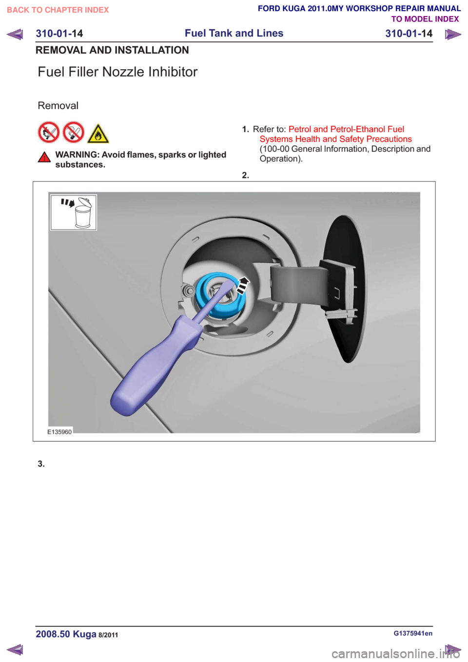
Fuel Filler Nozzle Inhibitor
Removal
WARNING: Avoid flames, sparks or lighted
substances.1.
Refer to: Petrol and Petrol-Ethanol Fuel
Systems Health and Safety Precautions
(100-00 General Information, Description and
Operation).
2.
E135960
3.
G1375941en2008.50 Kuga8/2011
310-01- 14
Fuel Tank and Lines
310-01- 14
REMOVAL AND INSTALLATION
TO MODEL INDEX
BACK TO CHAPTER INDEX
FORD KUGA 2011.0MY WORKSHOP REPAIR MANUAL
Page 2007 of 2057
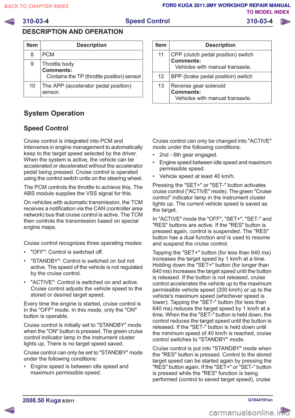
Description
Item
PCM
8
Throttle body
Comments:Contains the TP (throttle position) sensor
9
The APP (accelerator pedal position)
sensor.
10Description
Item
CPP (clutch pedal position) switch
Comments:Vehicles with manual transaxle.
11
BPP (brake pedal position) switch
12
Reverse gear solenoid
Comments:Vehicles with manual transaxle.
13
System Operation
Speed Control
Cruise control is integrated into PCM and
intervenes in engine management to automatically
keep to the target speed selected by the driver.
When the system is active, the vehicle can be
accelerated or decelerated without the accelerator
pedal being pressed. Cruise control is operated
using the control switch units on the steering wheel.
The PCM controls the throttle to achieve this. The
ABS module supplies the VSS signal for this.
On vehicles with automatic transmission, the TCM
receives a notification via the CAN (controller area
network) bus that cruise control is active. The TCM
then controls the transmission based on special
engine maps.
Cruise control recognizes three operating modes:
• "OFF": Control is switched off.
• "STANDBY": Control is switched on but not
active. The speed of the vehicle is not regulated
by the cruise control.
• "ACTIVE": Control is switched on and active. Cruise control adjusts the vehicle speed to the
stored or desired target speed.
Every time the engine is started, cruise control is
in the "OFF" mode. In this mode, only the "ON"
button is operable.
Cruise control is initially set to "STANDBY" mode
when the "ON" button is pressed. The green cruise
control indicator lamp in the instrument cluster
lights up. There is no target speed saved.
Cruise control can only be set to "STANDBY" mode
under the following conditions:
• Engine speed is between idle speed and maximum permissible speed. Cruise control can only be changed into "ACTIVE"
mode under the following conditions:
• 2nd - 6th gear engaged.
• Engine speed between idle speed and maximum
permissible speed.
• Vehicle speed at least 40 km/h.
Pressing the "SET+" or "SET-" button activates
cruise control ("ACTIVE" mode). The green "Cruise
control" indicator lamp in the instrument cluster
lights up. The current vehicle speed is saved as
the target.
In "ACTIVE" mode the "OFF", "SET+", "SET-" and
"RES" buttons are active. If the "RES" button is
pressed again, control is suspended. The "RES"
button has a dual function and is used to resume
and suspend the cruise control.
Tapping the "SET+" button (for less than 640 ms)
increases the target speed by 1 km/h at a time.
Holding down the "SET+" button (for longer than
640 ms) increases the target speed until the button
is released. If the button is not released, cruise
control accelerates the vehicle up to the maximum
permissible vehicle speed (200 km/h) or up to the
vehicle's maximum speed (whichever speed is
lower). Tapping the "SET-" button (for less than
640 ms) reduces the target speed by 1 km/h at a
time. When the the "SET-" button is held down, the
control reduces the target speed until the button is
released. If the "SET-" button is held down until
the minimum speed of 40 km/h is reached, cruise
control switches to "STANDBY" mode.
Cruise control is put into "STANDBY" mode when
the "RES" button is pressed. Control to the stored
target speed can be started again by pressing the
"RES" button again. If the "SET+" or "SET-" button
is pressed while the "RES" function is being
performed (control to saved target speed), cruise
G1044191en2008.50 Kuga8/2011
310-03- 4
Speed Control
310-03- 4
DESCRIPTION AND OPERATION
TO MODEL INDEX
BACK TO CHAPTER INDEX
FORD KUGA 2011.0MY WORKSHOP REPAIR MANUAL
Page 2008 of 2057
control saves the current speed as the target
speed.
Cruise control goes into STANDBY mode in the
following situations:
• Operation of the brake pedal
• Operation of the clutch pedal
• Operation of the parking brake
• If the driver operates the accelerator pedal andthe saved target speed is subsequently
exceeded for more than 5 minutes.
• Pressing any cruise control button for more than 2 minutes
• Intervention by the traction control or electronic stability program (for longer than 40 ms)
• Shifting of the gear selector lever to the "N" position (vehicles with automatic transmission
only)
• Minimum speed falls below 40 km/h.
• Occurrence of particular DTC (diagnostic trouble code)
• faulty signal from the backup lamp switch
Cruise control is switched off when the "OFF"
button is pressed.
If the accelerator pedal is pressed down, the
vehicle speed increases. As soon as the pedal is
released, the speed falls to the saved target value. The following components supply the signals
needed by the cruise control:
• The APP sensor.
– The APP sensor identifies the currentposition of the accelerator pedal and sends
a PWM (pulse width modulation) signal to
the PCM and an analog DC (direct current)
signal to the GEM.
– If one or both of the APP sensors fails, a fault is stored in the PCM fault memory and cruise
control cannot be activated.
• BPP switch – The BPP switch tells the PCM whether thevehicle is being braked. In its rest state the
switch is closed and sends an earth signal
to the GEM. This signal is sent via the CAN
to the PCM.
– The brake light switch is likewise connected to the GEM and is opened in the rest state.
When the vehicle is braked, the brake light
switch sends a signal to the GEM. This
compares the signals from the BPP switch
and the brake light switch. If a discrepancy
occurs, a fault is stored in the error memory
of the GEM. Cruise control cannot be
activated.
• CPP switch – The CPP switch sends a ground signal to theGEM as soon as the clutch is operated. This
signal is passed on by the GEM via the CAN
bus to the PCM. This then supplies the signal
to the cruise control.
– If the CPP switch is incorrectly installed or set, cruise control cannot be activated.
• Wheel speed sensors – The wheel speed sensors record the speedof all the wheels. The recorded speed values
are sent to the ABS module via a hard-wired
connection. The ABS module calculates a
vehicle speed signal (VS signal) from the
speed values and the wheel diameter. This
vehicle speed signal is transferred via the
CAN bus to the PCM and supplied to the
cruise control. If the vehicle speed signal is
faulty, cruise control cannot be activated.
G1044191en2008.50 Kuga8/2011
310-03- 5
Speed Control
310-03- 5
DESCRIPTION AND OPERATION
TO MODEL INDEX
BACK TO CHAPTER INDEX
FORD KUGA 2011.0MY WORKSHOP REPAIR MANUAL
Page 2009 of 2057
• Parking brake switch.– The parking brake switch is hard-wired to theGEM. The parking brake switch sends a
signal to the GEM when the parking brake is
operated. The GEM activates the parking
brake indicator lamp in the instrument cluster.
If the parking brake indicator lamp is lit,
cruise control cannot be activated.
• Back-up light switch – The backup lamp switch is hard-wired to the GEM. The backup lamp switch sends a signal
to the GEM when reverse gear is engaged.
The GEM activates the reversing lamp.
Cruise control cannot be activated when
reverse gear is engaged.
Component Description
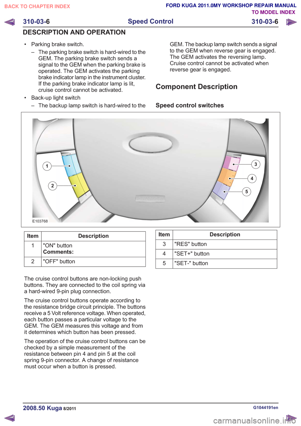
Speed control switches
E103768
3
4
5
1
2
Description
Item
"ON" button
Comments:
1
"OFF" button
2Description
Item
"RES" button
3
"SET+" button
4
"SET-" button
5
The cruise control buttons are non-locking push
buttons. They are connected to the coil spring via
a hard-wired 9-pin plug connection.
The cruise control buttons operate according to
the resistance bridge circuit principle. The buttons
receive a 5 Volt reference voltage. When operated,
each button passes a particular voltage to the
GEM. The GEM measures this voltage and from
it determines which button has been pressed.
The operation of the cruise control buttons can be
checked by a simple measurement of the
resistance between pin 4 and pin 5 at the coil
spring 9-pin connector. A change of resistance
must occur when a button is pressed.
G1044191en2008.50 Kuga8/2011
310-03- 6
Speed Control
310-03- 6
DESCRIPTION AND OPERATION
TO MODEL INDEX
BACK TO CHAPTER INDEX
FORD KUGA 2011.0MY WORKSHOP REPAIR MANUAL