2011 FORD KUGA ELECTRICAL
[x] Cancel search: ELECTRICALPage 1695 of 2057
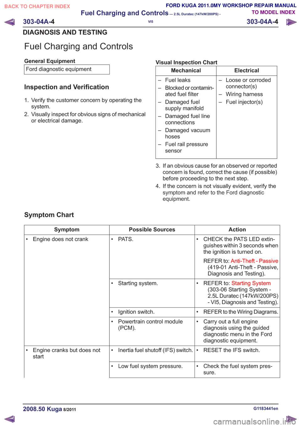
Fuel Charging and Controls
General EquipmentFord diagnostic equipment
Inspection and Verification
1. Verify the customer concern by operating the system.
2. Visually inspect for obvious signs of mechanical or electrical damage. Visual Inspection Chart
Electrical
Mechanical
– Loose or corrodedconnector(s)
– Wiring harness
– Fuel injector(s)
– Fuel leaks
– Blocked or contamin-
ated fuel filter
– Damaged fuel supply manifold
– Damaged fuel line connections
– Damaged vacuum hoses
– Fuel rail pressure sensor
3. If an obvious cause for an observed or reported concern is found, correct the cause (if possible)
before proceeding to the next step.
4. If the concern is not visually evident, verify the symptom and refer to the Ford diagnostic
equipment .
Symptom Chart
Action
Possible Sources
Symptom
• CHECK the PATS LED extin-guishes within 3 seconds when
the ignition is turned on.
REFER to: Anti-Theft - Passive
(419-01 Anti-Theft - Passive,
Diagnosis and Testing).
• PAT S .
• Engine does not crank
• REFER to:Starting System
(303-06 Starting System -
2.5L Duratec (147kW/200PS)
- VI5, Diagnosis and Testing).
• Starting system.
• REFER to the Wiring Diagrams.
• Ignition switch.
• Carry out a full enginediagnosis using the guided
diagnostic menu in the Ford
diagnostic equipment.
• Powertrain control module
(PCM).
• RESET the IFS switch.
• Inertia fuel shutoff (IFS) switch.
• Engine cranks but does not
start
• Check the fuel system pres-sure.
• Low fuel system pressure.
G1183441en2008.50 Kuga8/2011
303-04A-
4
Fuel Charging and Controls
— 2.5L Duratec (147kW/200PS) -
VI5
303-04A- 4
DIAGNOSIS AND TESTING
TO MODEL INDEX
BACK TO CHAPTER INDEX
FORD KUGA 2011.0MY WORKSHOP REPAIR MANUAL
Page 1725 of 2057
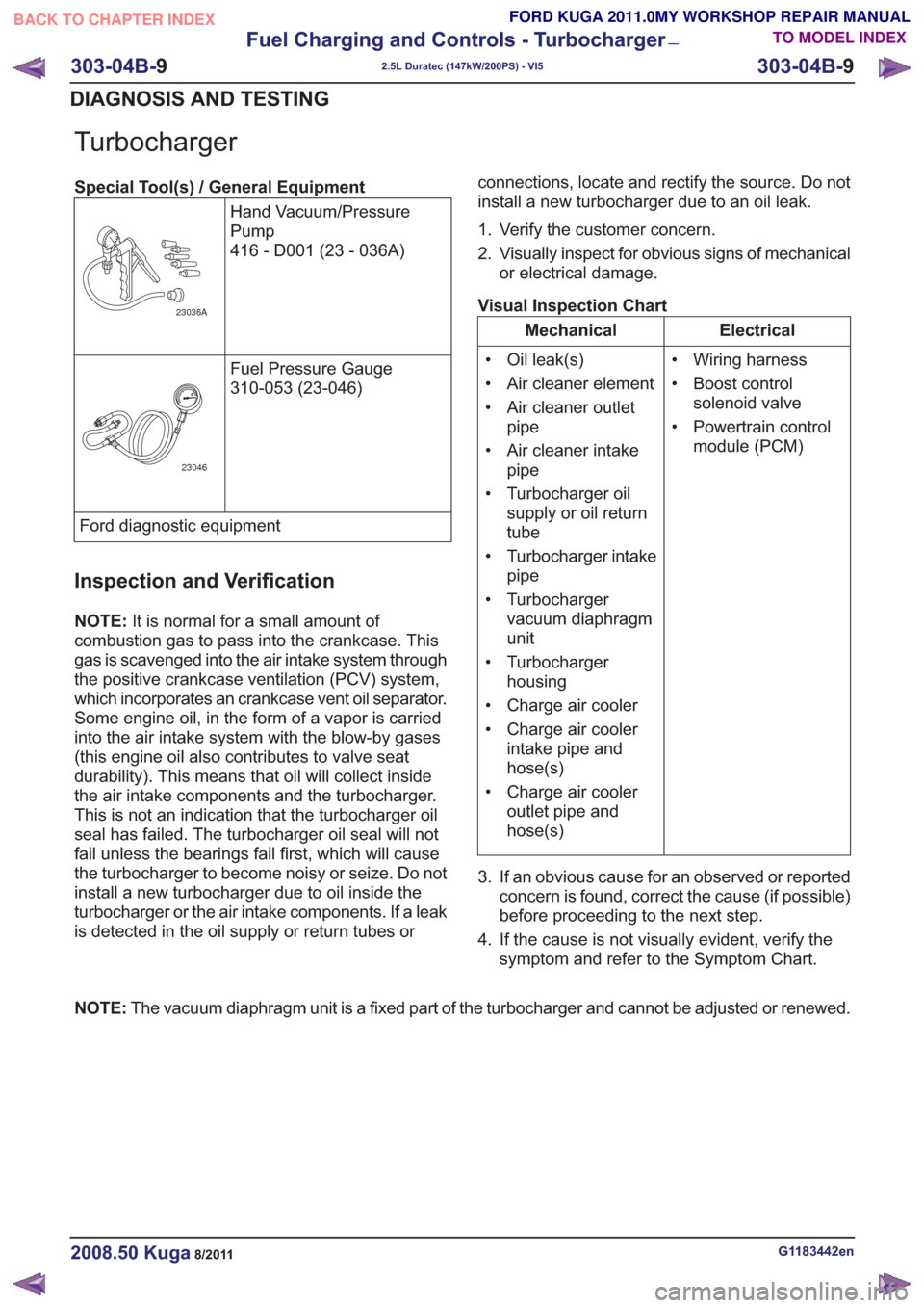
Turbocharger
Special Tool(s) / General EquipmentHand Vacuum/Pressure
Pump
416 - D001 (23 - 036A)
23036A
Fuel Pressure Gauge
310-053 (23-046)
23046
Ford diagnostic equipment
Inspection and Verification
NOTE:It is normal for a small amount of
combustion gas to pass into the crankcase. This
gas is scavenged into the air intake system through
the positive crankcase ventilation (PCV) system,
which incorporates an crankcase vent oil separator.
Some engine oil, in the form of a vapor is carried
into the air intake system with the blow-by gases
(this engine oil also contributes to valve seat
durability). This means that oil will collect inside
the air intake components and the turbocharger.
This is not an indication that the turbocharger oil
seal has failed. The turbocharger oil seal will not
fail unless the bearings fail first, which will cause
the turbocharger to become noisy or seize. Do not
install a new turbocharger due to oil inside the
turbocharger or the air intake components. If a leak
is detected in the oil supply or return tubes or connections, locate and rectify the source. Do not
install a new turbocharger due to an oil leak.
1. Verify the customer concern.
2. Visually inspect for obvious signs of mechanical
or electrical damage.
Visual Inspection Chart
Electrical
Mechanical
• Wiring harness
• Boost controlsolenoid valve
• Powertrain control module (PCM)
• Oil leak(s)
• Air cleaner element
• Air cleaner outlet
pipe
• Air cleaner intake pipe
• Turbocharger oil supply or oil return
tube
• Turbocharger intake pipe
• Turbocharger vacuum diaphragm
unit
• Turbocharger housing
• Charge air cooler
• Charge air cooler intake pipe and
hose(s)
• Charge air cooler outlet pipe and
hose(s)
3. If an obvious cause for an observed or reported concern is found, correct the cause (if possible)
before proceeding to the next step.
4. If the cause is not visually evident, verify the symptom and refer to the Symptom Chart.
NOTE: The vacuum diaphragm unit is a fixed part of the turbocharger and cannot be adjusted or renewed.
G1183442en2008.50 Kuga8/2011
303-04B- 9
Fuel Charging and Controls - Turbocharger
—
2.5L Duratec (147kW/200PS) - VI5
303-04B- 9
DIAGNOSIS AND TESTING
TO MODEL INDEX
BACK TO CHAPTER INDEX
FORD KUGA 2011.0MY WORKSHOP REPAIR MANUAL
Page 1737 of 2057
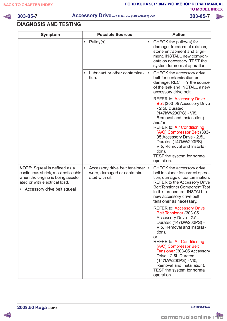
Action
Possible Sources
Symptom
• CHECK the pulley(s) fordamage, freedom of rotation,
stone entrapment and align-
ment. INSTALL new compon-
ents as necessary. TEST the
system for normal operation.
• Pulley(s).
• CHECK the accessory drivebelt for contamination or
damage. RECTIFY the source
of the leak and INSTALL a new
accessory drive belt.
REFER to: Accessory Drive
Belt (303-05 Accessory Drive
- 2.5L Duratec
(147kW/200PS) - VI5,
Removal and Installation).
and/or
REFER to: Air Conditioning
(A/C) Compressor Belt (303-
05 Accessory Drive - 2.5L
Duratec (147kW/200PS) -
VI5, Removal and Installa-
tion).
TEST the system for normal
operation.
• Lubricant or other contamina-
tion.
• CHECK the accessory drivebelt tensioner for correct opera-
tion, damage or contamination.
REFER to the Accessory Drive
Belt Tensioner Component Test
in this procedure. INSTALL a
new accessory drive belt
tensioner as necessary.
REFER to: Accessory Drive
Belt Tensioner (303-05
Accessory Drive - 2.5L
Duratec (147kW/200PS) -
VI5, Removal and Installa-
tion).
or
REFER to: Air Conditioning
(A/C) Compressor Belt
Tensioner (303-05 Accessory
Drive - 2.5L Duratec
(147kW/200PS) - VI5,
Removal and Installation).
TEST the system for normal
operation.
• Accessory drive belt tensioner
worn, damaged or contamin-
ated with oil.
NOTE:
Squeal is defined as a
continuous shriek, most noticeable
when the engine is being acceler-
ated or with electrical load.
• Accessory drive belt squeal
G1183443en2008.50 Kuga8/2011
303-05- 7
Accessory Drive— 2.5L Duratec (147kW/200PS) - VI5303-05-
7
DIAGNOSIS AND TESTING
TO MODEL INDEX
BACK TO CHAPTER INDEX
FORD KUGA 2011.0MY WORKSHOP REPAIR MANUAL
Page 1753 of 2057
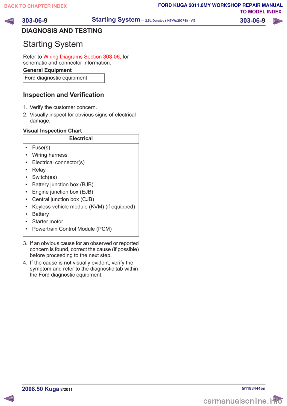
Starting System
Refer toWiring Diagrams Section 303-06, for
schematic and connector information.
General Equipment
Ford diagnostic equipment
Inspection and Verification
1. Verify the customer concern.
2. Visually inspect for obvious signs of electrical damage.
Visual Inspection Chart
Electrical
• Fuse(s)
• Wiring harness
• Electrical connector(s)
• Relay
• Switch(es)
• Battery junction box (BJB)
• Engine junction box (EJB)
• Central junction box (CJB)
• Keyless vehicle module (KVM) (if equipped)
• Battery
• Starter motor
• Powertrain Control Module (PCM)
3. If an obvious cause for an observed or reported concern is found, correct the cause (if possible)
before proceeding to the next step.
4. If the cause is not visually evident, verify the symptom and refer to the diagnostictab within
the Ford diagnostic equipment .
G1183444en2008.50 Kuga8/2011
303-06-9
Starting System— 2.5L Duratec (147kW/200PS) - VI5303-06-
9
DIAGNOSIS AND TESTING
TO MODEL INDEX
BACK TO CHAPTER INDEX
FORD KUGA 2011.0MY WORKSHOP REPAIR MANUAL
Page 1758 of 2057
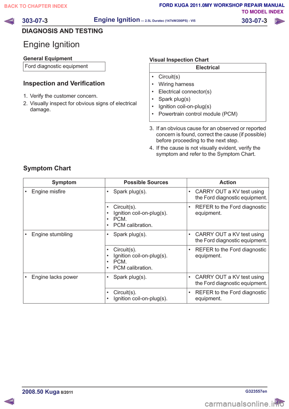
Engine Ignition
General EquipmentFord diagnostic equipment
Inspection and Verification
1. Verify the customer concern.
2. Visually inspect for obvious signs of electrical damage. Visual Inspection Chart
Electrical
• Circuit(s)
• Wiring harness
• Electrical connector(s)
• Spark plug(s)
• Ignition coil-on-plug(s)
• Powertrain control module (PCM)
3. If an obvious cause for an observed or reported concern is found, correct the cause (if possible)
before proceeding to the next step.
4. If the cause is not visually evident, verify the symptom and refer to the Symptom Chart.
Symptom Chart
Action
Possible Sources
Symptom
• CARRY OUT a KV test usingthe Ford diagnostic equipment.
• Spark plug(s).
• Engine misfire
• REFER to the Ford diagnosticequipment.
• Circuit(s).
• Ignition coil-on-plug(s).
•PCM.
• PCM calibration.
• CARRY OUT a KV test usingthe Ford diagnostic equipment.
• Spark plug(s).
• Engine stumbling
• REFER to the Ford diagnosticequipment.
• Circuit(s).
• Ignition coil-on-plug(s).
•PCM.
• PCM calibration.
• CARRY OUT a KV test usingthe Ford diagnostic equipment.
• Spark plug(s).
• Engine lacks power
• REFER to the Ford diagnosticequipment.
• Circuit(s).
• Ignition coil-on-plug(s).
G323557en2008.50 Kuga8/2011
303-07-
3
Engine Ignition— 2.5L Duratec (147kW/200PS) - VI5303-07-
3
DIAGNOSIS AND TESTING
TO MODEL INDEX
BACK TO CHAPTER INDEX
FORD KUGA 2011.0MY WORKSHOP REPAIR MANUAL
Page 1763 of 2057
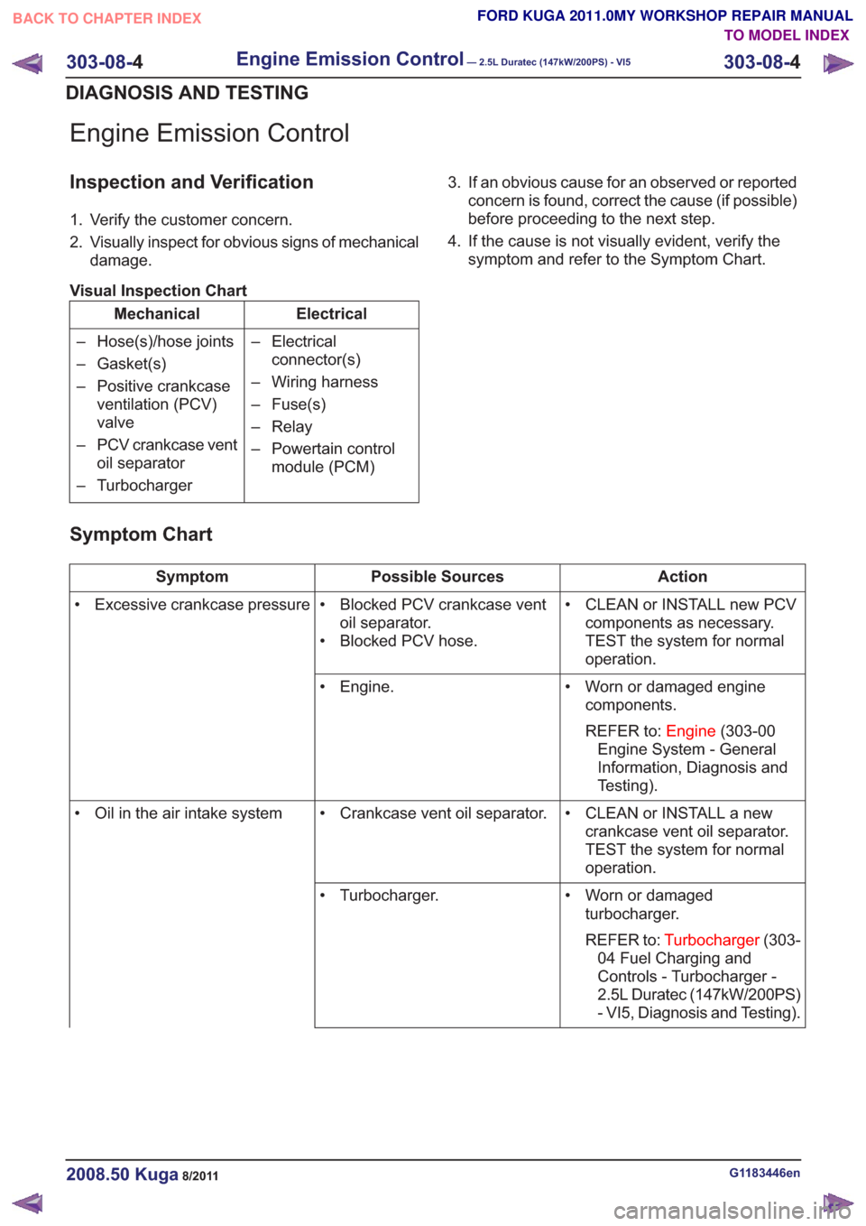
Engine Emission Control
Inspection and Verification
1. Verify the customer concern.
2. Visually inspect for obvious signs of mechanicaldamage.
Visual Inspection Chart
Electrical
Mechanical
– Electricalconnector(s)
– Wiring harness
– Fuse(s)
– Relay
– Powertain control module (PCM)
– Hose(s)/hose joints
– Gasket(s)
– Positive crankcase
ventilation (PCV)
valve
– PCV crankcase vent oil separator
– Turbocharger 3. If an obvious cause for an observed or reported
concern is found, correct the cause (if possible)
before proceeding to the next step.
4. If the cause is not visually evident, verify the symptom and refer to the Symptom Chart.
Symptom Chart
Action
Possible Sources
Symptom
• CLEAN or INSTALL new PCVcomponents as necessary.
TEST the system for normal
operation.
• Blocked PCV crankcase vent
oil separator.
• Blocked PCV hose.
• Excessive crankcase pressure
• Worn or damaged enginecomponents.
REFER to: Engine(303-00
Engine System - General
Information, Diagnosis and
Testing).
• Engine.
• CLEAN or INSTALL a newcrankcase vent oil separator.
TEST the system for normal
operation.
• Crankcase vent oil separator.
• Oil in the air intake system
• Worn or damagedturbocharger.
REFER to: Turbocharger (303-
04 Fuel Charging and
Controls - Turbocharger -
2.5L Duratec (147kW/200PS)
- VI5, Diagnosis and Testing).
• Turbocharger.
G1183446en2008.50 Kuga8/2011
303-08-
4
Engine Emission Control— 2.5L Duratec (147kW/200PS) - VI5303-08-
4
DIAGNOSIS AND TESTING
TO MODEL INDEX
BACK TO CHAPTER INDEX
FORD KUGA 2011.0MY WORKSHOP REPAIR MANUAL
Page 1768 of 2057
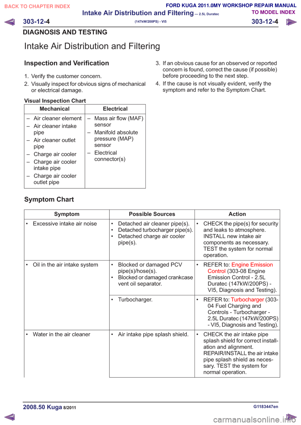
Intake Air Distribution and Filtering
Inspection and Verification
1. Verify the customer concern.
2. Visually inspect for obvious signs of mechanicalor electrical damage.
Visual Inspection Chart
Electrical
Mechanical
– Mass air flow (MAF)sensor
– Manifold absolute pressure (MAP)
sensor
– Electrical connector(s)
– Air cleaner element
– Air cleaner intake
pipe
– Air cleaner outlet pipe
– Charge air cooler
– Charge air cooler intake pipe
– Charge air cooler outlet pipe 3. If an obvious cause for an observed or reported
concern is found, correct the cause (if possible)
before proceeding to the next step.
4. If the cause is not visually evident, verify the symptom and refer to the Symptom Chart.
Symptom Chart
Action
Possible Sources
Symptom
• CHECK the pipe(s) for securityand leaks to atmosphere.
INSTALL new intake air
components as necessary.
TEST the system for normal
operation.
• Detached air cleaner pipe(s).
• Detached turbocharger pipe(s).
• Detached charge air cooler
pipe(s).
• Excessive intake air noise
• REFER to:Engine Emission
Control (303-08 Engine
Emission Control - 2.5L
Duratec (147kW/200PS) -
VI5, Diagnosis and Testing).
• Blocked or damaged PCV
pipe(s)/hose(s).
• Blocked or damaged crankcase vent oil separator.
• Oil in the air intake system
• REFER to:Turbocharger(303-
04 Fuel Charging and
Controls - Turbocharger -
2.5L Duratec (147kW/200PS)
- VI5, Diagnosis and Testing).
• Turbocharger.
• CHECK the air intake pipesplash shield for correct install-
ation and alignment.
REPAIR/INSTALL the air intake
pipe splash shield as neces-
sary. TEST the system for
normal operation.
• Air intake pipe splash shield.
• Water in the air cleaner
G1183447en2008.50 Kuga8/2011
303-12- 4
Intake Air Distribution and Filtering
— 2.5L Duratec
(147kW/200PS) - VI5
303-12- 4
DIAGNOSIS AND TESTING
TO MODEL INDEX
BACK TO CHAPTER INDEX
FORD KUGA 2011.0MY WORKSHOP REPAIR MANUAL
Page 1774 of 2057
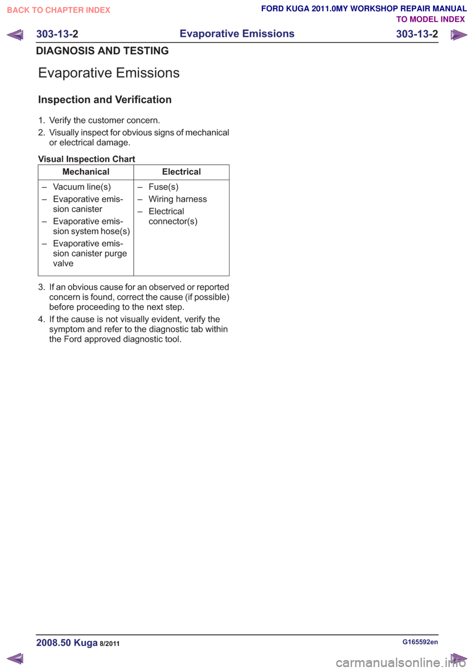
Evaporative Emissions
Inspection and Verification
1. Verify the customer concern.
2. Visually inspect for obvious signs of mechanicalor electrical damage.
Visual Inspection Chart
Electrical
Mechanical
– Fuse(s)
– Wiring harness
– Electricalconnector(s)
– Vacuum line(s)
– Evaporative emis-
sion canister
– Evaporative emis- sion system hose(s)
– Evaporative emis- sion canister purge
valve
3. If an obvious cause for an observed or reported concern is found, correct the cause (if possible)
before proceeding to the next step.
4. If the cause is not visually evident, verify the symptom and refer to the diagnostic tab within
the Ford approved diagnostic tool.
G165592en2008.50 Kuga8/2011
303-13- 2
Evaporative Emissions
303-13- 2
DIAGNOSIS AND TESTING
TO MODEL INDEX
BACK TO CHAPTER INDEX
FORD KUGA 2011.0MY WORKSHOP REPAIR MANUAL