2011 FORD KUGA ELECTRICAL
[x] Cancel search: ELECTRICALPage 1808 of 2057
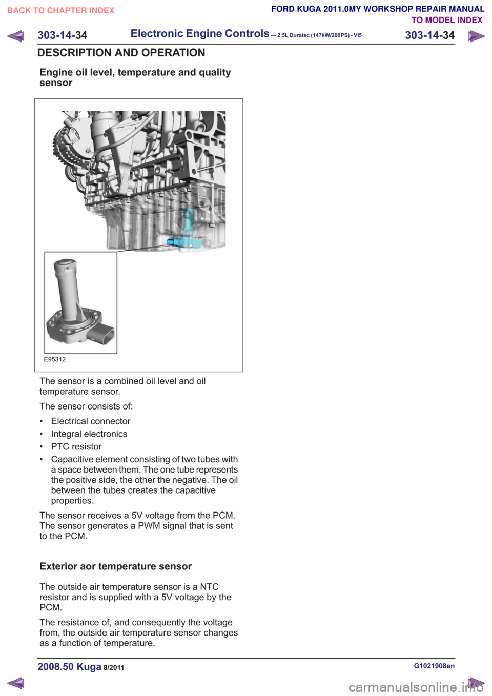
Engine oil level, temperature and quality
sensor
E95312
The sensor is a combined oil level and oil
temperature sensor.
The sensor consists of:
• Electrical connector
• Integral electronics
• PTC resistor
• Capacitive element consisting of two tubes witha space between them. The one tube represents
the positive side, the other the negative. The oil
between the tubes creates the capacitive
properties.
The sensor receives a 5V voltage from the PCM.
The sensor generates a PWM signal that is sent
to the PCM.
Exterior aor temperature sensor
The outside air temperature sensor is a NTC
resistor and is supplied with a 5V voltage by the
PCM.
The resistance of, and consequently the voltage
from, the outside air temperature sensor changes
as a function of temperature.
G1021908en2008.50 Kuga8/2011
303-14- 34
Electronic Engine Controls— 2.5L Duratec (147kW/200PS) - VI5303-14-
34
DESCRIPTION AND OPERATION
TO MODEL INDEX
BACK TO CHAPTER INDEX
FORD KUGA 2011.0MY WORKSHOP REPAIR MANUAL
Page 1809 of 2057
Electronic Engine Controls
General EquipmentFord diagnostic equipment
Inspection and Verification
1. Verify the customer concern.
2. Visually inspect for obvious signs of mechanical or electrical damage.
Visual Inspection Chart
Electrical
– Fuse(s)
– Wiring harness
– Electrical connector(s)
– Relay(s)
– Sensor(s)
– Switch(es)
– Powertrain control module (PCM)
3. If an obvious cause for an observed or reported concern is found, correct the cause (if possible)
before proceeding to the next step
4. If the cause is not visually evident, verify the symptom and refer to the Ford diagnostic
equipment to diagnose the system.
G165604en2008.50 Kuga8/2011
303-14- 35
Electronic Engine Controls— 2.5L Duratec (147kW/200PS) - VI5303-14-
35
DIAGNOSIS AND TESTING
TO MODEL INDEX
BACK TO CHAPTER INDEX
FORD KUGA 2011.0MY WORKSHOP REPAIR MANUAL
Page 1831 of 2057
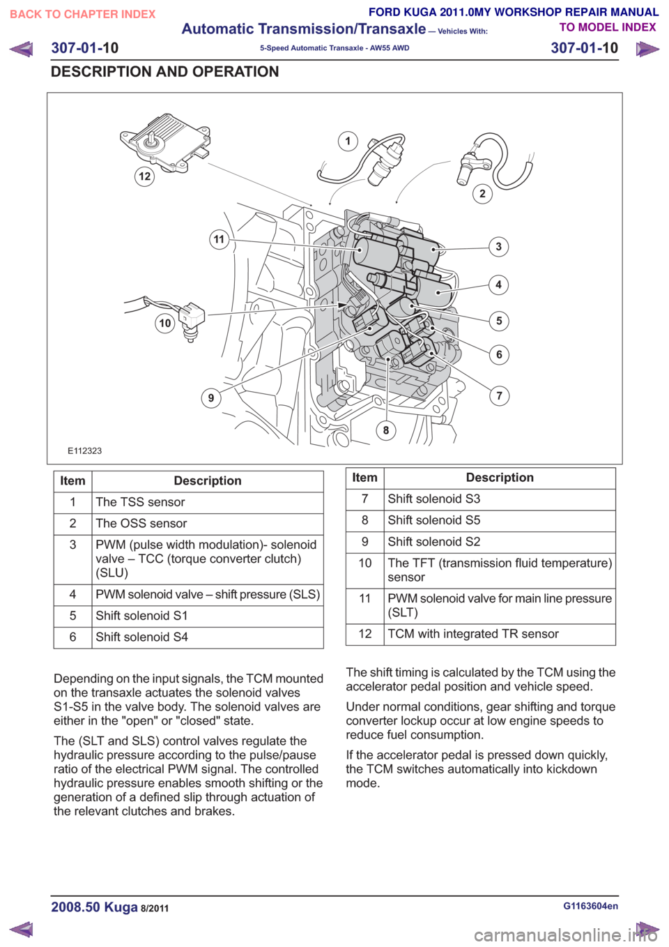
E112323
1
2
7
6
4
5
3
10
9
11
12
Description
Item
The TSS sensor
1
The OSS sensor
2
PWM (pulse width modulation)- solenoid
valve – TCC (torque converter clutch)
(SLU)
3
PWM solenoid valve – shift pressure (SLS)
4
Shift solenoid S1
5
Shift solenoid S4
6Description
Item
Shift solenoid S3
7
Shift solenoid S5
8
Shift solenoid S2
9
The TFT (transmission fluid temperature)
sensor
10
PWM solenoid valve for main line pressure
(SLT)
11
TCM with integrated TR sensor
12
Depending on the input signals, the TCM mounted
on the transaxle actuates the solenoid valves
S1-S5 in the valve body. The solenoid valves are
either in the "open" or "closed" state.
The (SLT and SLS) control valves regulate the
hydraulic pressure according to the pulse/pause
ratio of the electrical PWM signal. The controlled
hydraulic pressure enables smooth shifting or the
generation of a defined slip through actuation of
the relevant clutches and brakes. The shift timing is calculated by the TCM using the
accelerator pedal position and vehicle speed.
Under normal conditions, gear shifting and torque
converter lockup occur at low engine speeds to
reduce fuel consumption.
If the accelerator pedal is pressed down quickly,
the TCM switches automatically into kickdown
mode.
G1163604en2008.50 Kuga8/2011
307-01-
10
Automatic Transmission/Transaxle
— Vehicles With:
5-Speed Automatic Transaxle - AW55 AWD
307-01- 10
DESCRIPTION AND OPERATION
TO MODEL INDEX
BACK TO CHAPTER INDEX
FORD KUGA 2011.0MY WORKSHOP REPAIR MANUAL
Page 1835 of 2057
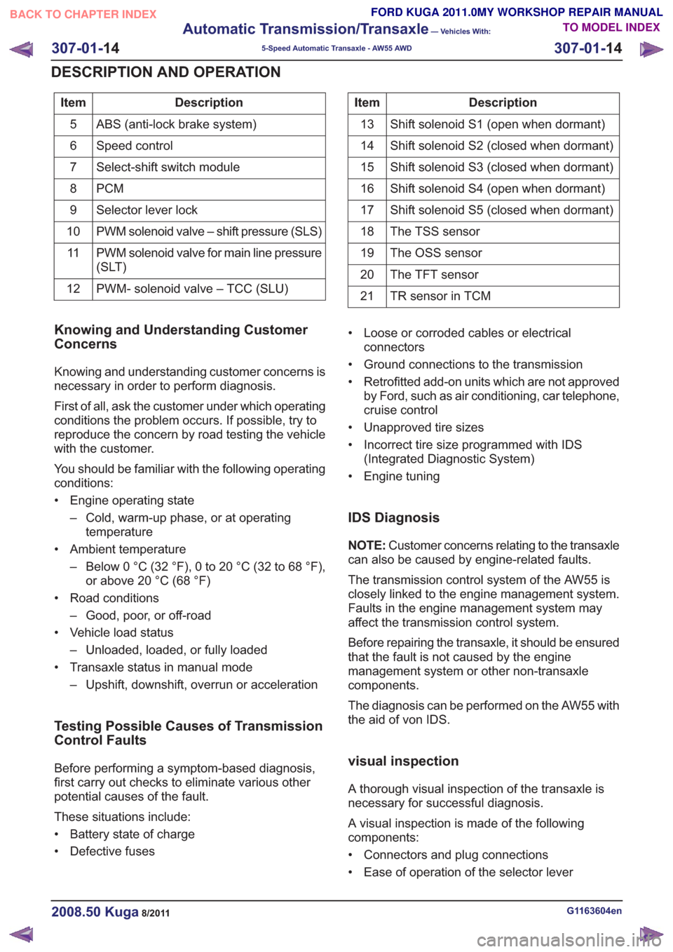
Description
Item
ABS (anti-lock brake system)
5
Speed control
6
Select-shift switch module
7
PCM
8
Selector lever lock
9
PWM solenoid valve – shift pressure (SLS)
10
PWM solenoid valve for main line pressure
(SLT)
11
PWM- solenoid valve – TCC (SLU)
12Description
Item
Shift solenoid S1 (open when dormant)
13
Shift solenoid S2 (closed when dormant)
14
Shift solenoid S3 (closed when dormant)
15
Shift solenoid S4 (open when dormant)
16
Shift solenoid S5 (closed when dormant)
17
The TSS sensor
18
The OSS sensor
19
The TFT sensor
20
TR sensor in TCM
21
Knowing and Understanding Customer
Concerns
Knowing and understanding customer concerns is
necessary in order to perform diagnosis.
First of all, ask the customer under which operating
conditions the problem occurs. If possible, try to
reproduce the concern by road testing the vehicle
with the customer.
You should be familiar with the following operating
conditions:
• Engine operating state
– Cold, warm-up phase, or at operatingtemperature
• Ambient temperature – Below 0 °C (32 °F), 0 to 20 °C (32 to 68 °F),or above 20 °C (68 °F)
• Road conditions – Good, poor, or off-road
• Vehicle load status – Unloaded, loaded, or fully loaded
• Transaxle status in manual mode – Upshift, downshift, overrun or acceleration
Testing Possible Causes of Transmission
Control Faults
Before performing a symptom-based diagnosis,
first carry out checks to eliminate various other
potential causes of the fault.
These situations include:
• Battery state of charge
• Defective fuses • Loose or corroded cables or electrical
connectors
• Ground connections to the transmission
• Retrofitted add-on units which are not approved by Ford, such as air conditioning, car telephone,
cruise control
• Unapproved tire sizes
• Incorrect tire size programmed with IDS (Integrated Diagnostic System)
• Engine tuning
IDS Diagnosis
NOTE: Customer concerns relating to the transaxle
can also be caused by engine-related faults.
The transmission control system of the AW55 is
closely linked to the engine management system.
Faults in the engine management system may
affect the transmission control system.
Before repairing the transaxle, it should be ensured
that the fault is not caused by the engine
management system or other non-transaxle
components.
The diagnosis can be performed on the AW55 with
the aid of von IDS.
visual inspection
A thorough visual inspection of the transaxle is
necessary for successful diagnosis.
A visual inspection is made of the following
components:
• Connectors and plug connections
• Ease of operation of the selector lever
G1163604en2008.50 Kuga8/2011
307-01- 14
Automatic Transmission/Transaxle
— Vehicles With:
5-Speed Automatic Transaxle - AW55 AWD
307-01- 14
DESCRIPTION AND OPERATION
TO MODEL INDEX
BACK TO CHAPTER INDEX
FORD KUGA 2011.0MY WORKSHOP REPAIR MANUAL
Page 1842 of 2057
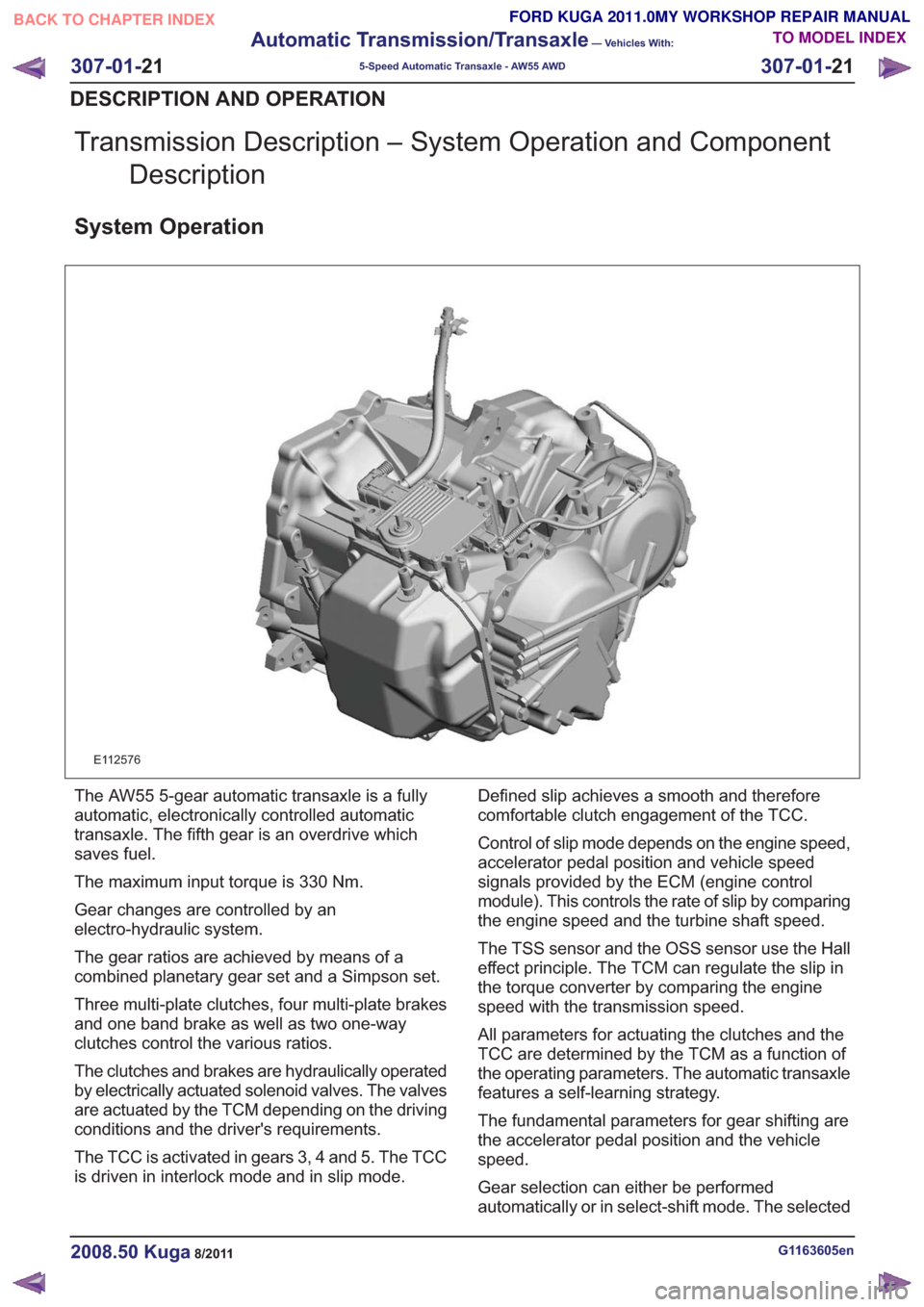
Transmission Description – System Operation and ComponentDescription
System Operation
E112576
The AW55 5-gear automatic transaxle is a fully
automatic, electronically controlled automatic
transaxle. The fifth gear is an overdrive which
saves fuel.
The maximum input torque is 330 Nm.
Gear changes are controlled by an
electro-hydraulic system.
The gear ratios are achieved by means of a
combined planetary gear set and a Simpson set.
Three multi-plate clutches, four multi-plate brakes
and one band brake as well as two one-way
clutches control the various ratios.
The clutches and brakes are hydraulically operated
by electrically actuated solenoid valves. The valves
are actuated by the TCM depending on the driving
conditions and the driver's requirements.
The TCC is activated in gears 3, 4 and 5. The TCC
is driven in interlock mode and in slip mode. Defined slip achieves a smooth and therefore
comfortable clutch engagement of the TCC.
Control of slip mode depends on the engine speed,
accelerator pedal position and vehicle speed
signals provided by the ECM (engine control
module). This controls the rate of slip by comparing
the engine speed and the turbine shaft speed.
The TSS sensor and the OSS sensor use the Hall
effect principle. The TCM can regulate the slip in
the torque converter by comparing the engine
speed with the transmission speed.
All parameters for actuating the clutches and the
TCC are determined by the TCM as a function of
the operating parameters. The automatic transaxle
features a self-learning strategy.
The fundamental parameters for gear shifting are
the accelerator pedal position and the vehicle
speed.
Gear selection can either be performed
automatically or in select-shift mode. The selected
G1163605en2008.50 Kuga8/2011
307-01-
21
Automatic Transmission/Transaxle
— Vehicles With:
5-Speed Automatic Transaxle - AW55 AWD
307-01- 21
DESCRIPTION AND OPERATION
TO MODEL INDEX
BACK TO CHAPTER INDEX
FORD KUGA 2011.0MY WORKSHOP REPAIR MANUAL
Page 1843 of 2057
transmission range or gear (in select-shift mode)
is indicated to the driver in the instrument panel.
In selector lever position "S", the driver can
manually select the gears (select-shift mode). Up
(+) and down (-) shifts are made by moving the
selector lever in the appropriate direction.
Hydraulic limp home modes maintain limited
operation in the event of failure of important
electrical components.Under normal conditions, the transmission fluid is
filled for the service life of the transaxle and does
not need to be changed.
A dipstick is used to check the fluid level in the
transmission.
Functionality overview
G1163605en2008.50 Kuga8/2011
307-01-
22
Automatic Transmission/Transaxle
— Vehicles With:
5-Speed Automatic Transaxle - AW55 AWD
307-01- 22
DESCRIPTION AND OPERATION
TO MODEL INDEX
BACK TO CHAPTER INDEX
FORD KUGA 2011.0MY WORKSHOP REPAIR MANUAL
Page 1845 of 2057
Description
Item
The TR sensor
3
The TSS sensor
4
The TFT sensor
5
TCM6Description
Item
OSS (output shaft speed) sensor
7
Solenoid valves in valve body
8
Clutches and brakes
9
TCC
10
The function is divided into an electronic and a
hydraulic control system.
Electronic Control System
Depending on the input signals, the TCM mounted
on the transmission actuates the solenoid valves
in the valve body. The TCM calculates and stores
adaptive data, fault codes and values for diagnosis.
The TR sensor is integrated in the TCM.
Hydraulic Control System
When the engine is running, a fluid pump integrated
in the transaxle housing generates the hydraulic pressure required for controlling the automatic
transaxle.
Through actuation of the solenoid valves, hydraulic
pressure is applied to the clutches and brakes via
hydraulic channels in the valve body and the
transaxle. The control valves regulate the hydraulic
pressure in accordance with the duty cycle of the
electrical PWM signal. The controlled hydraulic
pressure enables smooth shifting or the generation
of a defined slip through actuation of the relevant
clutches and brakes.
Solenoid valves are either in the 'open' or 'closed'
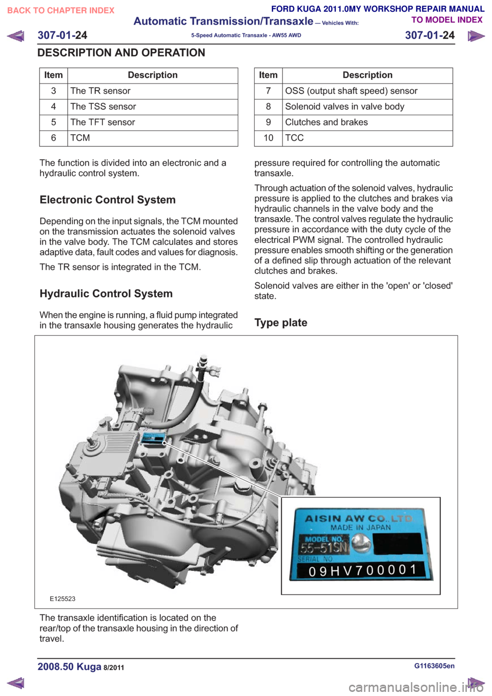
state.Type plate
E125523
The transaxle identification is located on the
rear/top of the transaxle housing in the direction of
travel.
G1163605en2008.50 Kuga8/2011
307-01-
24
Automatic Transmission/Transaxle
— Vehicles With:
5-Speed Automatic Transaxle - AW55 AWD
307-01- 24
DESCRIPTION AND OPERATION
TO MODEL INDEX
BACK TO CHAPTER INDEX
FORD KUGA 2011.0MY WORKSHOP REPAIR MANUAL
Page 1852 of 2057
The TCM detects uphill driving by comparing the
engine load transmitted by the PCM with the engine
speed. If the engine load increases and the engine
speed falls, then the TCM causes the transaxle to
shift to a lower transmission range in order to
increase the traction force.
Downhill driving
The TCM detects downhill driving by comparing
the engine load and engine speed values
transmitted by the PCM with the OSS sensor
signal. In order to prevent overloading of the
vehicle brakes, the TCM causes the transaxle to
shift to a lower transmission range.
Hill-hold function
If the vehicle is stopped on an uphill incline, the
TCM detects this through the faster drop in engine
speed compared with the drop in engine speed
when stopping on the flat. In this situation, the
hydraulics are actuated by the TCM in such a way
that the vehicle is prevented from rolling back. This
function is not used on steep inclines.
If the vehicle is parked on an uphill incline (ignition
switched off), the hill-hold function is not active
when pulling away.
Altitude correction
Lower air density results in reduced engine
performance. In order to compensate for this
operating situation, the TCM changes the shift
points.
Selector lever lock
To prevent the selector lever being accidentally
moved from the P or N position, the vehicle also
has an electrically operated selector lever lock.
This blocks the locking pin in the locking segment
and thus locks the selector lever in the P or N
position.
Shifting from P into another transmission
range
To be able to move the selector lever from P into
another transmission range, the ignition must be
switched on and the brake pedal must be
depressed (stop light switch on). The TCM detects
the position of the brake pedal via the CAN data
bus and the engaged transmission range from the
TR sensor.
The signal is then transferred from the TCM to the
select-shift switch module in order to activate the
solenoid valve in the selector mechanism
assembly.
In position P, the solenoid valve is activated and
the locking pin is pulled in so that the lock button
on the selector lever can be pressed as usual to
engage another transmission range.
In the selector mechanism assembly there is a Hall
sensor which is affected by a permanent magnet
on the gate of the selector mechanism assembly.
If the selector lever is moved from the P position,
both the Hall sensor and the selector lever lock
solenoid are simultaneously deactivated, to prevent
the selector from being kept in the N position.
If the ignition is set to "I" or "0" the solenoid valve
is deactivated. When the selector lever is in the P
position, it is mechanically locked because it has
no voltage.
Shifting from N into another transmission
range
The conditions are the same as for shifting from P
into another transmission range.
However, the lock button on the selector lever must
be pressed to be able to select R or P.
Power flow through the transmission
Clutches and brakes
G1163605en2008.50 Kuga8/2011
307-01-31
Automatic Transmission/Transaxle
— Vehicles With:
5-Speed Automatic Transaxle - AW55 AWD
307-01- 31
DESCRIPTION AND OPERATION
TO MODEL INDEX
BACK TO CHAPTER INDEX
FORD KUGA 2011.0MY WORKSHOP REPAIR MANUAL