Page 239 of 297

7-34
INSPECTION AND MAINTENANCE
80J23-03E
trailer). Contact your dealer for further
information.
Actual weight of the loaded vehicle
and actual loads at the front and rear
axles can only be determined by
weighing the vehicle using a vehicle
scale. To measure the weight and
load, try making your vehicle to a high-
way weighing station, shipping com-
pany or inspection station for trucks,
etc. Compare these weights to the
GVWR and GAWR (front and rear)
listed on the Safety Certification Label.
If the gross vehicle weight or the load
on either axle exceeds these ratings,
you must remove enough weight to
bring the load down to the rated
capacity.Steps for Determining Correct Load
Limit
1) Locate the statement “The com-
bined weight of occupants and
cargo should never exceed XXX kg
or XXX lbs” on your vehicle’s plac-
ard.
2) Determine the combined weight of
the driver and passengers that will
be riding in your vehicle.
3) Subtract the combined weight of
the driver and passengers from
XXX kg or XXX lbs.
4) The resulting figure equals the
available amount of cargo and lug-
gage load capacity. For example, if
the “XXX” amount equals 1400 lbs
and there will be five 150 lb passen-
gers in your vehicle, the amount of
available cargo and luggage load
capacity is 650 lbs (1400 – 750 (5 x
150) = 650 lbs).
5) Determine the combined weight of
luggage and cargo being loaded on
the vehicle. That weight may not
safely exceed the available cargo
and luggage load capacity calcu-
lated in Step 4.
6) If your vehicle will be towing a
trailer, load from your trailer will be
transferred to your vehicle. Consult
this manual to determine how this
reduces the available cargo and lug-
gage load capacity of your vehicle.
WARNING
Never overload your vehicle. Over-
loading your vehicle can cause
damage to your tires and lead to
poor steering and braking which
can result in an accident. The
gross vehicle weight (sum of the
weights of the loaded vehicle,
driver and passengers) must
never exceed the Gross Vehicle
Weight Rating (GVWR) listed on
the Safety Certification Label. In
addition, never distribute a load so
that the weight on either the front
or rear axle exceeds the Gross
Axle Weight Rating (GAWR) listed
on the Safety Certification Label.
WARNING
Always distribute cargo evenly.
To avoid personal injury or
damage to your vehicle, always
secure cargo to prevent it from
shifting if the vehicle moves
suddenly.
Place heavier objects on the
floor and as far forward in the
cargo area as possible. Never
pile cargo higher than the top of
the seatbacks.
Page 240 of 297

7-35INSPECTION AND MAINTENANCE
80J23-03E
Vehicle Loading Example
As an example, suppose that the Tire
and Loading Information label on your
vehicle indicates that your vehicle’s
total load capacity is 950 lbs. If you
were to drive your vehicle with one
passenger, and the total combined
weight of you and your passenger was
350 lbs, then the cargo and luggage
capacity of your vehicle would be 600
lbs (950 – 350 = 600 lbs).
If you later added 2 more passengers,
having a combined weight of 325 lbs,
the cargo and luggage capacity of
your vehicle would be reduced from
600 lbs to 275 lbs (600 – 325 = 275
lbs). As you can see, as the number
and combined weight of vehicle occu-
pants increase, the vehicle’s cargo
and luggage capacity decreases.
Suppose again, that you were to take
a trip in your vehicle with the same
three passengers described above,
and you decided to tow a trailer having
a trailer tongue weight of 75 lbs. The
cargo and luggage capacity would be
reduced again, to 200 lbs (275 – 75 =
200 lbs).Determining Compatibility of Tire
and Vehicle Load Limits
The tires on your vehicle, when they
are inflated to the recommended tire
inflation pressure, have a load-carry-
ing capacity that is greater than the
load that will be on the tires when the
vehicle is at its GVWR or GAWR limit.
Never use replacement tires that have
a load-carrying capacity less than the
original tires on your vehicle. Tire load-
carrying capacity information is
molded into the tire sidewall typically
shown as “Max. Load”. Use of replace-
ment tires with a lower load-carrying
capacity than the original tires, or fail-
ure to keep the tires inflated to recom-
mended tire pressure, may reduce the
GVWR or GAWR limit of your vehicle.
NOTE:
Use of replacement tires with a higher
load-carrying capacity than the origi-
nal tires, or using a tire inflation pres-
sure higher than the recommended
tire inflation pressure, will not increase
the GVWR or GAWR limit of your vehi-
cle.
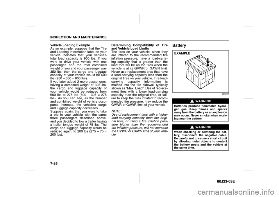
Battery
60A269
WARNING
Batteries produce flammable hydro-
gen gas. Keep flames and sparks
away from the battery or an explosion
may occur. Never smoke when work-
ing near the battery.
WARNING
When checking or servicing the bat-
tery, disconnect the negative cable.
Be careful not to cause a short circuit
by allowing metal objects to contact
the battery posts and the vehicle at
the same time.EXAMPLE
Page 251 of 297
7-46
INSPECTION AND MAINTENANCE
80J23-03E
80JM076
3) Pushing the unguiform prongs (3)
toward inside and remove the bulb
holder (4).
4) Replace the bulbs.
To install a high-mounted stop light
housing in the reverse order of removal.SX4 SEDAN
80JM132
To remove the high-mounted stop light
housing, pinch both side of the clip (1) and
push it in.
Wiper Blades
80G083
If the wiper blades become brittle or dam-
aged, or make streaks when wiping,
replace the wiper blades.
To install new wiper blades, follow the pro-
cedures below.
NOTE:
Some wiper blades may be different from
the ones described here depending on
vehicle specifications. If so, consult your
SUZUKI dealer for proper replacement
method.
(3) (3)
(4)
(1)
CAUTION
To avoid scratching or breaking the
window, do not let the wiper arm
strike the window while replacing the
wiper blade.
Page 252 of 297
7-47INSPECTION AND MAINTENANCE
80J23-03E
For windshield wipers and some rear
wipers:
70G119
1) Hold the wiper arm away from the win-
dow.
NOTE:
When raising both of the front wiper arms,
pull the driver’s side wiper arm up first.
When returning the wiper arms, lower the
passenger’s side wiper arm first. Other-
wise, the wiper arms may interfere with
each other.
52D102
2) Squeeze lock lever (1) towards wiper
arm (2) and remove the wiper frame
from the arm as shown.
60A260
3) Pull the locked end of the wiper blade
firmly to unlock the blade and slide the
blade out as shown.
Page 253 of 297
7-48
INSPECTION AND MAINTENANCE
80J23-03E
52D124
(3) Retainer
4) If the new blade is provided without the
two metal retainers, move them from
the old blade to the new one.Installation
52D125
(4) Locked end
5) Install the new blade in the reverse
order of removal, with the locked end
positioned toward the wiper arm. Make
sure the blade is properly retained by
all the hooks. Grasp the blade near the
locked end and pull in the direction of
the arrows to lock the end into place.
6) Reinstall wiper frame to arm, making
sure that the lock lever is snapped
securely into the arm.To remove some types of rear wiper
frame from the wiper arm:
1) Hold the arm away from the window.
80G146
2) Remove the wiper frame from the arm
as shown.
Page 257 of 297
EMERGENCY SERVICE
8
80J23-03E
60G411
EMERGENCY SERVICETire Changing Tool ............................................................. 8-1
Jacking Instructions ........................................................... 8-2
Changing Wheels ................................................................ 8-4
Jump Starting Instructions ................................................ 8-5
Towing a Disabled Vehicle ................................................. 8-6
If the Starter Does Not Operate .......................................... 8-6
If the Engine is Flooded ...................................................... 8-7
If the Engine Overheats ...................................................... 8-7
Page 258 of 297
8-1EMERGENCY SERVICE
80J23-03E
Tire Changing ToolSX4
80JC014
SX4 SEDAN
80JC045
The jack, wheel brace, jack handle are
stowed in the luggage compartment.
80J048
To remove the spare tire, turn its bolt (1)
counterclockwise and remove it.
79J085
To remove the jack, turn its shaft counter-
clockwise and pull the jack out of the stor-
age bracket.SX4
79J086
SX4 SEDAN
80JC015
To stow the jack, place it in the storage
bracket and turn the shaft clockwise until
the jack is securely held in place.
EXAMPLEEXAMPLE
(1)
EXAMPLE
Vehicle Loading: 11
Page 259 of 297

8-2
EMERGENCY SERVICE
80J23-03E
Jacking Instructions
75F062
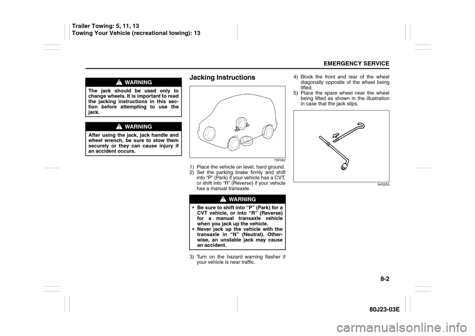
1) Place the vehicle on level, hard ground.
2) Set the parking brake firmly and shift
into “P” (Park) if your vehicle has a CVT,
or shift into “R” (Reverse) if your vehicle
has a manual transaxle.
3) Turn on the hazard warning flasher if
your vehicle is near traffic.4) Block the front and rear of the wheel
diagonally opposite of the wheel being
lifted.
5) Place the spare wheel near the wheel
being lifted as shown in the illustration
in case that the jack slips.
54G253
WARNING
The jack should be used only to
change wheels. It is important to read
the jacking instructions in this sec-
tion before attempting to use the
jack.
WARNING
After using the jack, jack handle and
wheel wrench, be sure to stow them
securely or they can cause injury if
an accident occurs.
WARNING
Be sure to shift into “P” (Park) for a
CVT vehicle, or into “R” (Reverse)
for a manual transaxle vehicle
when you jack up the vehicle.
Never jack up the vehicle with the
transaxle in “N” (Neutral). Other-
wise, an unstable jack may cause
an accident.
Trailer Towing: 5, 11, 13
Towing Your Vehicle (recreational towing): 13