2010 SUZUKI SX4 four wheel drive
[x] Cancel search: four wheel drivePage 104 of 297
3-3OPERATING YOUR VEHICLE
80J23-03E
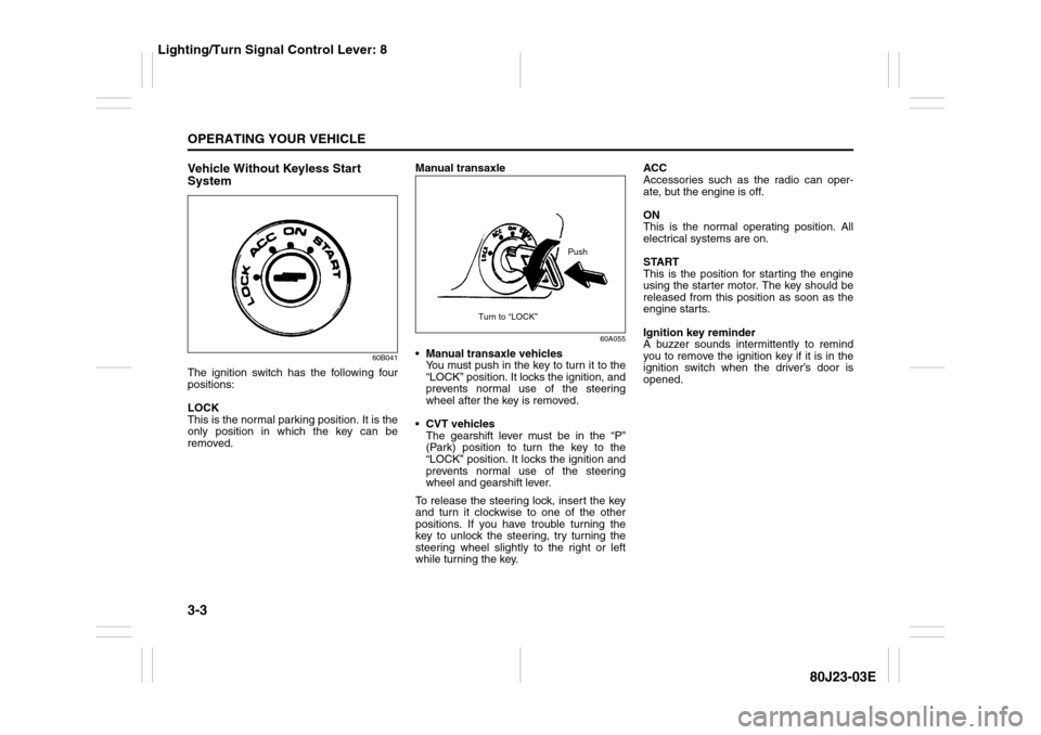
Vehicle Without Keyless Start
System
60B041
The ignition switch has the following four
positions:
LOCK
This is the normal parking position. It is the
only position in which the key can be
removed.Manual transaxle
60A055
Manual transaxle vehicles
You must push in the key to turn it to the
“LOCK” position. It locks the ignition, and
prevents normal use of the steering
wheel after the key is removed.
CVT vehicles
The gearshift lever must be in the “P”
(Park) position to turn the key to the
“LOCK” position. It locks the ignition and
prevents normal use of the steering
wheel and gearshift lever.
To release the steering lock, insert the key
and turn it clockwise to one of the other
positions. If you have trouble turning the
key to unlock the steering, try turning the
steering wheel slightly to the right or left
while turning the key.ACC
Accessories such as the radio can oper-
ate, but the engine is off.
ON
This is the normal operating position. All
electrical systems are on.
START
This is the position for starting the engine
using the starter motor. The key should be
released from this position as soon as the
engine starts.
Ignition key reminder
A buzzer sounds intermittently to remind
you to remove the ignition key if it is in the
ignition switch when the driver’s door is
opened.
Push
Turn to “LOCK”
Lighting/Turn Signal Control Lever: 8
Page 106 of 297
3-5OPERATING YOUR VEHICLE
80J23-03E
If you leave any of the doors open with the
ignition switch in the “ACC” position for a
while (and no key inserted), the engine
may not start when you turn the ignition
switch to “START”. If the engine does not
start, close all doors completely or turn the
ignition switch back to the “LOCK” position,
then start the engine.
The ignition switch has the following four
positions:
LOCK (1)
This is the normal parking position. It is the
only position in which the key can be
removed. It locks the ignition, and prevents
normal use of the steering wheel.
For vehicles with a CVT, the gearshift lever
must be in the “P” (Park) position to turn
the key to the “LOCK” position.
To release the steering lock, turn the igni-
tion switch clockwise to one of the other
positions. If you have trouble turning the
ignition switch to unlock the steering, try
turning the steering wheel slightly to the
right or left while turning the switch.
Manual transaxle vehicle
You must push in the ignition switch to
turn it from the “LOCK” position to the
“ACC” position. To return to the “LOCK”
position from the “ACC” position, turn the
ignition switch counterclockwise while
pushing in the switch.CVT vehicle
To turn the ignition switch, push the
switch.
ACC (2)
Accessories such as the radio can oper-
ate, but the engine is off.
ON (3)
This is the normal operating position. All
electrical systems are on.
START (4)
This is the position for starting the engine
using the starter motor. The switch should
be released from this position as soon as
the engine starts.
Ignition switch reminder
(When using the keyless start system)
A buzzer sounds intermittently to remind
you to return the ignition switch to the
“LOCK” position if it is in the “ACC” position
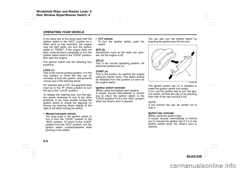
when the driver’s door is opened.You can also turn the ignition switch by
inserting the ignition key into the slot.
80JM139
The ignition switch cap (1) is installed to
make the ignition switch turn easily.
If you use the ignition key to turn the igni-
tion switch, remove the cap (1) by pinching
both side of the cap and pull it out.
NOTE:
If you remove the cap, be careful not to
lose it.
Ignition key reminder
(When using the ignition key)
A buzzer sounds intermittently to remind
you to remove the ignition key if it is in the
ignition switch when the driver’s door is
opened.
(1)
Windshield Wiper and Washer Lever: 8
Rear Window Wiper/Washer Switch: 8
Page 231 of 297
7-26
INSPECTION AND MAINTENANCE
80J23-03E
D. Construction Code
This letter code is used to indicate
the type of ply construction in the
tire. The letter “R” means radial
ply tire construction, the letter “D”
means diagonal or bias ply con-
struction, and the letter “B” means
belted-bias ply construction.
E. Rim Diameter
This two-digit number is the wheel
or rim diameter in inches.Tire Inflation Pressure
Tire inflation pressure should be
checked when the tire is cold. “Cold
tire inflation pressure” is the pressure
in a tire that has been driven less than
1 mile (1.6 km) or has been standing
for three hours or more.
80JS025
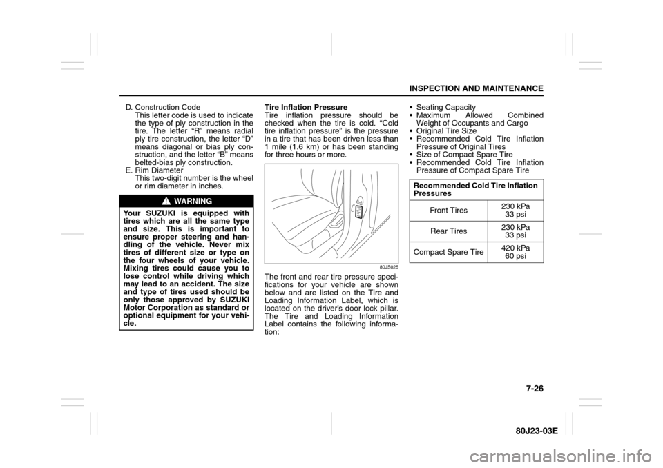
The front and rear tire pressure speci-
fications for your vehicle are shown
below and are listed on the Tire and
Loading Information Label, which is
located on the driver’s door lock pillar.
The Tire and Loading Information
Label contains the following informa-
tion: Seating Capacity
Maximum Allowed Combined
Weight of Occupants and Cargo
Original Tire Size
Recommended Cold Tire Inflation
Pressure of Original Tires
Size of Compact Spare Tire
Recommended Cold Tire Inflation
Pressure of Compact Spare Tire
WARNING
Your SUZUKI is equipped with
tires which are all the same type
and size. This is important to
ensure proper steering and han-
dling of the vehicle. Never mix
tires of different size or type on
the four wheels of your vehicle.
Mixing tires could cause you to
lose control while driving which
may lead to an accident. The size
and type of tires used should be
only those approved by SUZUKI
Motor Corporation as standard or
optional equipment for your vehi-
cle.
Recommended Cold Tire Inflation
Pressures
Front Tires230 kPa
33 psi
Rear Tires230 kPa
33 psi
Compact Spare Tire420 kPa
60 psi
Page 233 of 297
7-28
INSPECTION AND MAINTENANCE
80J23-03E
Tire Inspection
Inspect your vehicle’s tires at least
once a month by performing the fol-
lowing checks:
1) Measure the air pressure with a tire
gauge. Adjust the pressure if nec-
essary. Remember to check the
spare tire, too. Refer to the “Mea-
suring Air Pressure” section.
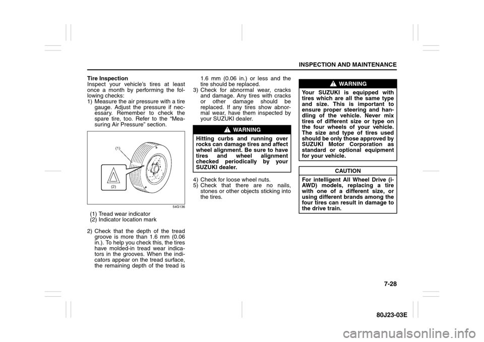
54G136
(1) Tread wear indicator
(2) Indicator location mark
2) Check that the depth of the tread
groove is more than 1.6 mm (0.06
in.). To help you check this, the tires
have molded-in tread wear indica-
tors in the grooves. When the indi-
cators appear on the tread surface,
the remaining depth of the tread is1.6 mm (0.06 in.) or less and the
tire should be replaced.
3) Check for abnormal wear, cracks
and damage. Any tires with cracks
or other damage should be
replaced. If any tires show abnor-
mal wear, have them inspected by
your SUZUKI dealer.
4) Check for loose wheel nuts.
5) Check that there are no nails,
stones or other objects sticking into
the tires.
WARNING
Hitting curbs and running over
rocks can damage tires and affect
wheel alignment. Be sure to have
tires and wheel alignment
checked periodically by your
SUZUKI dealer.
WARNING
Your SUZUKI is equipped with
tires which are all the same type
and size. This is important to
ensure proper steering and han-
dling of the vehicle. Never mix
tires of different size or type on
the four wheels of your vehicle.
The size and type of tires used
should be only those approved by
SUZUKI Motor Corporation as
standard or optional equipment
for your vehicle.
CAUTION
For intelligent All Wheel Drive (i-
AWD) models, replacing a tire
with one of a different size, or
using different brands among the
four tires can result in damage to
the drive train.
Page 237 of 297
7-32
INSPECTION AND MAINTENANCE
80J23-03E
Snow Tires
Your vehicle is equipped with all-sea-
son tires which are designed for use in
summer and most winter conditions.
For improved traction in severe winter
conditions, SUZUKI recommends
mounting radial snow tires on all four
wheels. Snow tires must be the same
size as the standard tires. Also be sure
to use the tires of the same type and
brand on all four wheels of your vehi-
cle.GLOSSARY OF TIRE TERMINOL-
OGY
Accessory Weight – the combined
weight (in excess of those standard
items which may be replaced) of CVT,
power steering, power brakes, power
windows, power seats, radio, and
heater, to the extent that these items
are available as factory-installed
equipment (whether installed or not).
Cold Tire Inflation Pressure – the pres-
sure in a tire that has been driven less
than 1 mile or has been standing for
three hours or more.
Curb Weight – the weight of a motor
vehicle with standard equipment
including the maximum capacity of
fuel, oil, and coolant, and, if so
equipped, air conditioning and addi-
tional weight optional engine.
Intended Outboard Sidewall – (1) the
sidewall that contains a whitewall,
bears white lettering or bears manu-
facturer, brand, and/or model name
molding that is higher or deeper than
the same molding on the other side-
wall of the tire, or (2) the outward fac-
ing sidewall of an asymmetrical tire
that has a particular side that must
always face outward when mounted
on a vehicle.Maximum Inflation Pressure – the max-
imum cold inflation pressure a tire is
designed to support in normal service.
Maximum Loaded Vehicle Weight –
the sum of curb weight, accessory
weight, vehicle capacity weight (total
load capacity), and production options
weight.
Normal Occupant Weight – 68 kilo-
grams times the number of occupants
specified in the second column of
Table 1 (shown below).
Occupant distribution – distribution of
occupants in a vehicle as specified in
the third column of Table 1 (shown
below).
Production Options Weight – the com-
bined weight of those installed regular
production options weighing over 2.3
kilograms in excess of those standard
items which they replace, not previ-
ously considered in curb weight or
accessory weight, including heavy
duty brakes, ride levelers, roof rack,
heavy duty battery, and special trim.
Recommended Inflation Pressure –
the cold tire inflation pressure recom-
mended by a manufacturer.
Rim – metal support for a tire or tire
and tube assembly upon which the tire
beads are seated.