2010 NISSAN TIIDA valve
[x] Cancel search: valvePage 883 of 3745

REAR DRUM BRAKEBR-35
< SERVICE INFORMATION >
C
DE
G H
I
J
K L
M A
B
BR
N
O P
REAR DRUM BRAKE
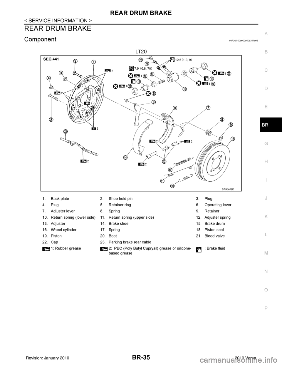
ComponentINFOID:0000000005397003
LT 2 0
SFIA3079E
1. Back plate 2. Shoe hold pin 3. Plug
4. Plug 5. Retainer ring 6. Operating lever
7. Adjuster lever 8. Spring 9. Retainer
10. Return spring (lower side) 11. Return spring (upper side) 12. Adjuster spring
13. Adjuster 14. Brake shoe 15. Brake drum
16. Wheel cylinder 17. Spring 18. Piston seal
19. Piston 20. Boot 21. Bleed valve
22. Cap 23. Parking brake rear cable
1: Rubber grease 2: PBC (Poly Butyl Cuprysil) grease or silicone-
based grease : Brake fluid
Revision: January 20102010 Versa
Page 884 of 3745

BR-36
< SERVICE INFORMATION >
REAR DRUM BRAKE
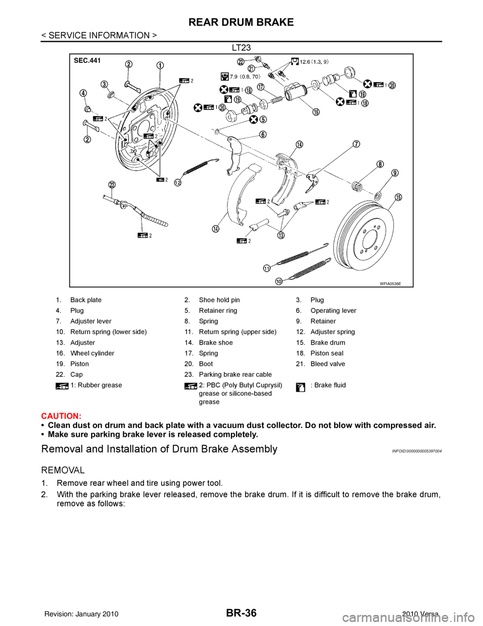
LT23
CAUTION:
• Clean dust on drum and back plate with a vacuum dust collector. Do not blow with compressed air.
• Make sure parking brake lever is released completely.
Removal and Installation of Drum Brake AssemblyINFOID:0000000005397004
REMOVAL
1. Remove rear wheel and tire using power tool.
2. With the parking brake lever released, remove the brak e drum. If it is difficult to remove the brake drum,
remove as follows:
WFIA0536E
1. Back plate 2. Shoe hold pin3. Plug
4. Plug 5. Retainer ring6. Operating lever
7. Adjuster lever 8. Spring9. Retainer
10. Return spring (lower side) 11. Return spring (upper side) 12. Adjuster spring
13. Adjuster 14. Brake shoe15. Brake drum
16. Wheel cylinder 17. Spring18. Piston seal
19. Piston 20. Boot21. Bleed valve
22. Cap 23. Parking brake rear cable
1: Rubber grease 2: PBC (Poly Butyl Cuprysil)
grease or silicone-based
grease : Brake fluid
Revision: January 20102010 Versa
Page 887 of 3745

REAR DRUM BRAKEBR-39
< SERVICE INFORMATION >
C
DE
G H
I
J
K L
M A
B
BR
N
O P
5. Connect the parking brake rear cable to the operating lever.
6. Install the shoe assembly. After assembly, be sure that each part is installed properly. CAUTION:
Do not damage the wheel cylinder piston boot.
7. Install the brake drum.
8. Depress brake pedal for several times (approximately 2 or 3 times).
9. Adjust clearance of brake shoe. Refer to PB-5, "
On-Vehicle Service".
10. Install rear wheel and tire. Refer to WT-7, "
Adjustment".
Removal and Installati on of Wheel CylinderINFOID:0000000005397005
REMOVAL
1. Drain the brake fluid. Refer to BR-9, "Drain and Refill".
2. Remove the rear brake shoe assembly. Refer to BR-36, "
Removal and Installation of Drum Brake Assem-
bly".
3. Remove the bleed valve.
4. Disconnect the brake tube from the wheel cylinder.
5. Remove the wheel cylinder bolts and then remove the wheel cylinder from the back plate.
INSTALLATION
Installation is in the reverse order of removal.
• Tighten bolts and bleed valve to the specified torque. Refer to BR-35, "
Component".
• Refill with new brake fluid and bleed the air. Refer to BR-9, "
Bleeding Brake System".
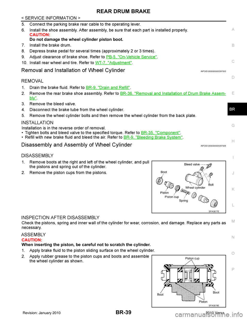
Disassembly and Assembly of Wheel CylinderINFOID:0000000005397006
DISASSEMBLY
1. Remove boots at the right and left of the wheel cylinder, and pull
the pistons and spring out of the cylinder.
2. Remove the piston cups from the pistons.
INSPECTION AFTER DISASSEMBLY
Check the pistons, spring and inner wall of the cylinder for wear, corrosion, and damage. Replace any parts as
necessary.
ASSEMBLY
CAUTION:
When inserting the piston, be caref ul not to scratch the cylinder.
1. Apply brake fluid to the piston sliding surface on the wheel cylinder.
2. Apply rubber grease to the piston cups and boots and assemble the wheel cylinder as shown.
SFIA3077E
SFIA3078E
Revision: January 20102010 Versa
Page 889 of 3745

SERVICE DATA AND SPECIFICATIONS (SDS)BR-41
< SERVICE INFORMATION >
C
DE
G H
I
J
K L
M A
B
BR
N
O P
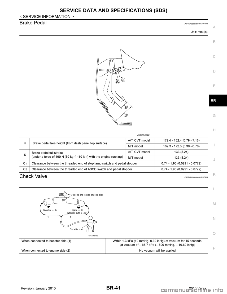
Brake PedalINFOID:0000000005397008
Unit: mm (in)
Check ValveINFOID:0000000005397009
H Brake pedal free height (from dash panel top surface) A/T, CVT model 172.4 - 182.4 (6.79 - 7.18)
M/T model
162.3 - 172.3 (6.39 - 6.78)
S Brake pedal full stroke
[under a force of 490 N (50 kg-f, 110 lb-f) with the engine running] A/T, CVT model
133 (5.24)
M/T model 133 (5.24)
C
1Clearance between the threaded end of stop lamp switch and pedal stopper 0.74 - 1.96 (0.0291 - 0.0772)
C
2Clearance between the threaded end of ASCD switch and pedal stopper 0.74 - 1.96 (0.0291 - 0.0772)
AWFIA0433ZZ
When connected to booster side (1)Within 1.3 kPa (10 mmHg, 0.39 inHg) of vacuum for 15 seconds
[at vacuum of – 66.7 kPa (– 500 mmHg, – 19.69 inHg]
When connected to engine side (2) No vacuum will be applied
SFIA0210E
Revision: January 20102010 Versa
Page 891 of 3745

BRC-1
BRAKES
C
DE
G H
I
J
K L
M
SECTION BRC
A
B
BRC
N
O P
CONTENTS
BRAKE CONTROL SYSTEM
ABS
SERVICE INFORMATION .. ..........................
3
PRECAUTIONS .............................................. .....3
Precaution for Supplemental Restraint System
(SRS) "AIR BAG" and "SEAT BELT PRE-TEN-
SIONER" ............................................................. ......
3
Precaution Necessary for Steering Wheel Rota-
tion After Battery Disconnect ............................... ......
3
Precaution for Brake System ....................................4
Precaution for Brake Control .....................................4
Precaution for CAN System ................................ ......4
PREPARATION ...................................................6
Special Service Tool ........................................... ......6
Commercial Service Tool ..........................................6
SYSTEM DESCRIPTION .....................................7
System Component ............................................. ......7
ABS Function ............................................................7
EBD Function ............................................................7
Fail-Safe Function .....................................................7
Hydraulic Circuit Diagram .........................................8
CAN COMMUNICATION ................................ .....9
System Description ............................................. ......9
TROUBLE DIAGNOSIS .....................................10
How to Perform Trouble Diagnosis for Quick and
Accurate Repair ......................................................
10
Component Parts and Harness Connector Loca-
tion ...................................................................... ....
13
Schematic ...............................................................14
Wiring Diagram - ABS - ...........................................15
Basic Inspection .................................................. ....18
Warning Lamp and Indicator Timing .......................19
Control Unit Input/Output Signal Standard ..............19
CONSULT-III Function (ABS) .................................20
TROUBLE DIAGNOSIS FOR SELF-DIAG-
NOSTIC ITEMS ..................................................
26
Wheel Sensor System ......................................... ....26
ABS Control Unit Inspection ....................................27
Solenoid Valve System Inspection ..........................27
Actuator Motor, Motor Relay, and Circuit Inspec-
tion ....................................................................... ....
28
ABS Control Unit Power and Ground Systems In-
spection ...................................................................
29
CAN Communication System Inspection .................30
TROUBLE DIAGNOSES FOR SYMPTOMS .....31
ABS Works Frequently ............................................31
Unexpected Pedal Action ........................................31
Long Stopping Distance ..........................................32
ABS Does Not Work ................................................32
Pedal Vibration or ABS Operation Noise .................32
WHEEL SENSORS ...........................................34
Removal and Installation ..................................... ....34
SENSOR ROTOR ..............................................36
Removal and Installation .........................................36
ACTUATOR AND ELECTRIC UNIT (ASSEM-
BLY) ..................................................................
37
Removal and Installation .........................................37
VDC/TCS/ABS
SERVICE INFORMATION .. .........................
39
PRECAUTIONS .................................................39
Precaution for Supplemental Restraint System
(SRS) "AIR BAG" and "SEAT BELT PRE-TEN-
SIONER" ............................................................. ....
39
Precaution Necessary for Steering Wheel Rota-
tion After Battery Disconnect ...................................
39
Precaution for Brake System ...................................40
Precaution for Brake Control ...................................40
Precaution for CAN System .....................................41
PREPARATION .................................................42
Special Service Tool ................................................42
Commercial Service Tool ........................................42
Revision: January 20102010 Versa
Page 892 of 3745

BRC-2
SYSTEM DESCRIPTION ................................ ...43
System Component ............................................. ...43
ABS Function ....................................... ...................43
EBD Function ...................................................... ...43
TCS Function ..........................................................44
VDC Function .........................................................44
Wheel Sensors .......................................................44
Fail-Safe Function ..................................................44
Hydraulic Circuit Diagram .......................................45
CAN COMMUNICATION ...................................46
System Description .................................................46
TROUBLE DIAGNOSIS .....................................47
How to Perform Trouble Diagnosis for Quick and
Accurate Repair ................................................... ...
47
Component Parts and Harness Connector Loca-
tion ..........................................................................
50
Schematic ...............................................................51
Wiring Diagram - VDC - ..........................................52
Basic Inspection .....................................................56
Warning Lamp and Indicator Timing .......................57
Control Unit Input/Output Signal Standard .............57
CONSULT-III Function (ABS) .................................60
TROUBLE DIAGNOSIS FOR SELF-DIAG-
NOSTIC ITEMS ............................................... ...
67
Wheel Sensor System Inspection ...........................67
Engine System Inspection ................................... ...68
ABS/TCS/VDC Control Unit Inspection ..................68
Steering Angle Sensor System Inspection .......... ...69
Yaw Rate/Side/Decel G Sensor System Inspec-
tion ....................................................................... ...
70
Solenoid and VDC Change-Over Valve System
Inspection ...............................................................
72
Actuator Motor, Motor Relay, and Circuit Inspec-
tion ....................................................................... ...
73
Stop Lamp Switch System Inspection ....................74
ABS/TCS/VDC Control Unit Power and Ground
Systems Inspection .............................................. ...
75
Brake Fluid Level Switch System Inspection ..........76
Pressure Sensor System Inspection .......................77
Transmission Range Switch System Inspection .. ...78
CAN Communication System Inspection ................79
Component Inspection ............................................79
TROUBLE DIAGNOSES FOR SYMPTOMS .....81
ABS Works Frequently ............................................81
Unexpected Pedal Action ..................................... ...81
Long Stopping Distance ..........................................82
ABS Does Not Work ...............................................82
Pedal Vibration or ABS Op eration Noise ................82
ABS Warning Lamp Does Not Come On When Ig-
nition Switch Is Turned On ................................... ...
83
ABS Warning Lamp Stays On When Ignition
Switch Is Turned On ............................................ ...
83
Vehicle Jerks During TCS/VDC Activation ..............84
ON-VEHICLE SERVICE ....................................85
Adjustment of Steering Angle Sensor Neutral Po-
sition ..................................................................... ...
85
WHEEL SENSORS ............................................86
Removal and Installation .........................................86
SENSOR ROTOR ........................................... ...88
Removal and Installation .........................................88
ACTUATOR AND ELECTRIC UNIT (ASSEM-
BLY) ................................................................ ...
89
Removal and Installation .........................................89
STEERING ANGLE SENSOR ........................ ...91
Removal and Installation .........................................91
G SENSOR ........................................................92
Removal and Installation .........................................92
Revision: January 20102010 Versa
Page 910 of 3745
![NISSAN TIIDA 2010 Service Repair Manual BRC-20
< SERVICE INFORMATION >[ABS]
TROUBLE DIAGNOSIS
Note 1: Confirm tire pressure is normal.
Note 2: ON/OFF timing of ABS warning lamp
ON: For approximately 2 seconds after ignition switch is turned NISSAN TIIDA 2010 Service Repair Manual BRC-20
< SERVICE INFORMATION >[ABS]
TROUBLE DIAGNOSIS
Note 1: Confirm tire pressure is normal.
Note 2: ON/OFF timing of ABS warning lamp
ON: For approximately 2 seconds after ignition switch is turned](/manual-img/5/57397/w960_57397-909.png)
BRC-20
< SERVICE INFORMATION >[ABS]
TROUBLE DIAGNOSIS
Note 1: Confirm tire pressure is normal.
Note 2: ON/OFF timing of ABS warning lamp
ON: For approximately 2 seconds after ignition switch is turned ON, or when a malfunction is detected.
OFF: Approximately 2 seconds after ignition switch is turned ON (when system is in normal operation).
CONSULT-III Function (ABS)INFOID:0000000005397039
CONSULT-III can display each diagnostic item us
ing the diagnostic test modes shown following.
Monitor itemDisplay content Data monitor
Note: Error inspection
checklist
Condition Reference value in
normal operation
FR RH SENSOR
FR LH SENSOR
RR RH SENSOR
RR LH SENSOR Wheel speedVehicle stopped
0 [km/h (MPH)]
BRC-26, "
Wheel Sensor
System"Vehicle running (Note 1) Almost in accor-
dance with speed-
ometer display
(within
±10%)
BATTERY VOLT Battery voltage sup-
plied to ABS actuator
and electric unit (con-
trol unit)Ignition switch ON
10 to 16VBRC-29, "
ABS Control
Unit Power and Ground
Systems Inspection"
STOP LAMP SW
Stop lamp switch oper-
ationBrake pedal depressed ON
—
Brake pedal not depressed OFF
ABS WARN LAMP ABS warning lamp ON
condition (Note 2)ABS warning lamp ON ON
BRC-18, "
Basic Inspec-
tion"ABS warning lamp OFF OFF
MOTOR RELAY Operation status of mo-
tor and motor relayIgnition switch ON or running
(ABS not activated)
OFF
BRC-28, "
Actuator Motor,
Motor Relay, and Circuit
Inspection"Ignition switch ON or engine
running (ABS activated) ON
ACTUATOR RLY Actuator relay opera-
tion statusVehicle stopped (Ignition
switch ON)
OFF
BRC-28, "
Actuator Motor,
Motor Relay, and Circuit
Inspection"Vehicle stopped (Engine run-
ning) ON
FR LH IN SOL
FR LH OUT SOL
FR RH IN SOL
FR RH OUT SOL
RR RH IN SOL
RR RH OUT SOL
RR LH IN SOL
RR LH OUT SOL Solenoid valve opera-
tionActuator (solenoid) is active
(“ACTIVE TEST” with CON-
SULT-III) or actuator relay is in-
active (in fail-safe mode).
ON
BRC-27, "
Solenoid Valve
System Inspection"When actuator (solenoid) is not
active and actuator relay is ac-
tive (ignition switch ON). OFF
ABS SIGNAL
EBD SIGNAL Signal statusABS active
EBD active
ON
ABS system
EBD system
ABS not active
EBD not active OFF
ABS FAIL SIG
EBD FAIL SIG Fail signal statusABS fail
EBD fail
ON
ABS system
EBD system
ABS normal
EBD normal OFF
Diagnostic mode
Description
SELF DIAGNOSTIC RESULT Displays ABS ac tuator and electric unit (control unit) self-diagnosis results.
DATA MONITOR Displays ABS actuator and electric unit (control unit) input/output data in real time.
CAN DIAG SUPPORT MNTR The result of transmit/receive diagnosis of CAN communication can be read. ACTIVE TEST Operation of electrical loads can be checked by sending drive signal to them.
Revision: January 20102010 Versa
Page 912 of 3745
![NISSAN TIIDA 2010 Service Repair Manual BRC-22
< SERVICE INFORMATION >[ABS]
TROUBLE DIAGNOSIS
Self-diagnostic item
Malfunction detecting condition Check system
RR RH SENSOR-1
[C1101] Circuit of rear RH wheel sensor is open.
BRC-26, "
Wheel NISSAN TIIDA 2010 Service Repair Manual BRC-22
< SERVICE INFORMATION >[ABS]
TROUBLE DIAGNOSIS
Self-diagnostic item
Malfunction detecting condition Check system
RR RH SENSOR-1
[C1101] Circuit of rear RH wheel sensor is open.
BRC-26, "
Wheel](/manual-img/5/57397/w960_57397-911.png)
BRC-22
< SERVICE INFORMATION >[ABS]
TROUBLE DIAGNOSIS
Self-diagnostic item
Malfunction detecting condition Check system
RR RH SENSOR-1
[C1101] Circuit of rear RH wheel sensor is open.
BRC-26, "
Wheel Sensor
System" (Note 1)
RR LH SENSOR-1
[C1102]
Circuit of rear LH wheel sensor is open.
FR RH SENSOR-1
[C1103] Circuit of front RH wheel sensor is open.
FR LH SENSOR-1
[C1104] Circuit of front LH wheel sensor is open.
RR RH SENSOR-2
[C1105] When the circuit in the rear RH wheel sensor is short-circuited or
when the sensor power voltage is outside the standard. When the
distance between the wheel sensor and sensor rotor is too large
and the sensor pulse cannot be recognized by the control unit.
RR LH SENSOR-2
[C1106] When the circuit in the rear LH wheel sensor is short-circuited or
when the sensor power voltage is outside the standard. When the
distance between the wheel sensor and sensor rotor is too large
and the sensor pulse cannot be recognized by the control unit.
FR RH SENSOR-2
[C1107] When the circuit in the front RH wheel sensor is short-circuited or
when the sensor power voltage is outside the standard. When the
distance between the wheel sensor and sensor rotor is too large
and the sensor pulse cannot be recognized by the control unit.
FR LH SENSOR-2
[C1108] When the circuit in the front LH wheel sensor is short-circuited or
when the sensor power voltage is outside the standard. When the
distance between the wheel sensor and sensor rotor is too large
and the sensor pulse cannot be recognized by the control unit.
ABS SENSOR
[ABNORMAL SIGNAL]
[ C 111 5 ] Wheel sensor input is abnormal.
BATTERY VOLTAGE
[ABNORMAL]
[C1109] ABS actuator and electric unit (control unit) power voltage is too
low. BRC-29, "
ABS Control
Unit Power and Ground
Systems Inspection"
CONTROLLER FAILURE
[ C 111 0 ]
Internal malfunction of ABS actuator
and electric unit (control unit)BRC-27, "ABS Control
Unit Inspection"
PUMP MOTOR
[ C 1111 ] During actuator motor operation with ON, when actuator motor
turns OFF or when control line for actuator motor relay is open.
BRC-28, "Actuator Mo-
tor, Motor Relay, and Cir-
cuit Inspection"During actuator motor operation with OFF, when actuator motor
turns ON or when control line for relay is shorted to ground.
FR LH IN ABS SOL
[C1120] Circuit of front LH IN ABS solenoid
is open or shorted, or control
line is open or shorted to power supply or ground.
BRC-27, "
Solenoid Valve
System Inspection"
FR LH OUT ABS SOL
[C1121]Circuit of front LH OUT ABS solenoid is open or shorted, or control
line is open or shorted to power supply or ground.
FR RH IN ABS SOL
[C1122] Circuit of front RH IN ABS solenoid is open or shorted, or control
line is open or shorted to power supply or ground.
FR RH OUT ABS SOL
[C1123] Circuit of front RH OUT ABS solenoid is open or shorted, or con-
trol line is open or shorted to power supply or ground.
RR LH IN ABS SOL
[C1124] Circuit of rear LH IN ABS solenoid
is open or shorted, or control
line is open or shorted to power supply or ground.
RR LH OUT ABS SOL
[C1125] Circuit of rear LH OUT ABS solenoid is open or shorted, or control
line is open or shorted to power supply or ground.
RR RH IN ABS SOL
[C1126] Circuit of rear RH IN ABS solenoid
is open or shorted, or control
line is open or shorted to power supply or ground.
RR RH OUT ABS SOL
[C1127] Circuit of rear RH OUT ABS solenoid is open or shorted, or control
line is open or shorted to power supply or ground.
Revision: January 20102010 Versa